For a research project and demonstrator at HSLU university I have to measure voltage a DC voltage and current. For this I’m planning to use the Texas Instrument Texas Instruments INA260, so I had to quickly develop a software driver for it.
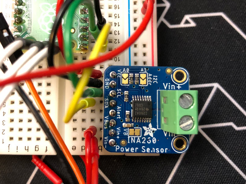
For a research project and demonstrator at HSLU university I have to measure voltage a DC voltage and current. For this I’m planning to use the Texas Instrument Texas Instruments INA260, so I had to quickly develop a software driver for it.
For systematic debugging, an engineer needs a debug probe. For the Raspberry Pi Pico (RP2040) device there are plenty of debug options with VS Code.
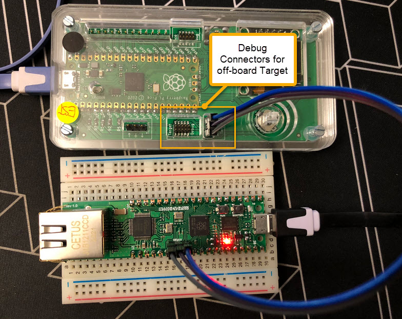
In this article I show different options, from professional tools to DIY solutions and the settings in VS Code I’m using.
Continue readingIn Getting Started: Raspberry Pi Pico RP2040 with Eclipse and J-Link I used a SEGGER J-Link EDU for debugging: unfortunately, probably because of silicon shortage, these EDU probes are out of stock everywhere. Luckily, there is a solution: just use another Raspberry Pi Pico!

This turns a $5 Raspberry Pi Pico board in to a very usable and versatile debug probe.
Continue readingAs promised I’m going to share more details about the “60 Billion Lights” project. It is about a project to build a piece of electronics behind a 100×50 cm canvas to show animations or to display information like temperature, humidity, weather, time or just any arbitrary text.

Writing text
It is one thing to create something ‘cool’ or technically interesting. But it is a completely different story to convince your girlfriend, partner, wife, family (or whatever you can name it) to hang something on a wall in our house or office. Then it is not about technology: it is more about design and art. So here is my attempt to solve that challenge:

Displaying temperature with a painted canvas, stepper motors and 2400 RGB LEDs
The NXP LPC55S69-EVK is a versatile board. In this article I show how it can be used with Adafruit TFT LCD boards, both with resistive and capacitive touch. For the software I’m using the open source LittlevGL GUI.

LPC55S69-EVK with Adafruit Touch LCD
In my previous article “Debug and Execute Code from FLASH on the Seeed Arch Mix NXP i.MX RT1052 Board” I explained how to take complete control over the board and flash and debug a firmware. Of course this overwrites the one which comes by default shipped on the board. This article is about how to restore or update the original firmware.

Restored Seeed Firmware
There are different ways to ruin a Linux system. For the Raspberry Pi which uses a micro SD card as the storage device by default, it comes with two challenges:
For problem one I do I have a mitigation strategy (see “Log2Ram: Extending SD Card Lifetime for Raspberry Pi LoRaWAN Gateway“). Problem two can occur by user error (“you shall not turn it off without a sudo poweroff!”) or with the event of a power outage or black out. So for that problem I wanted to build a UPS for the Raspberry Pi.

Raspberry Pi with UPS System and tinyK22
I’m using the VL6180X ToF (Time-of-Flight) sensors successfully in different projects. The VL6180X is great, but only can measure distances up to 20 cm and in ‘extended mode’ up to 60 cm. For a project I need to go beyond that, so the logical choice is the VL53L0X which measures between 30 cm and 100 cm or up to 200 cm. For this project I’m using the VL53L0X breakout board from Adafruit, but similar products are available e.g. from Pololu.

NXP K20dx128 with Adafruit VL53LOx tof sensor
The Teensy boards are great, but as they are they are not really useful for real development, as they lack proper SWD debugging. In “Modifying the Teensy 3.5 and 3.6 for ARM SWD Debugging” I have found a way to get SWD debugging working, at that time with Kinetis Design Studio and the Segger J-Link. This article is about how debug the Teensy with free MCUXpresso IDE and the $20 NXP LPC-Link2 debug probe:
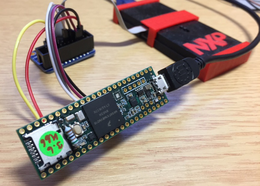
Teensy 3.6 with NXP LPC-Link2
