There are different ways to ruin a Linux system. For the Raspberry Pi which uses a micro SD card as the storage device by default, it comes with two challenges:
- Excessive writes to the SD card can wear it out
- Sudden power failure during a SD card write can corrupt the file system
For problem one I do I have a mitigation strategy (see “Log2Ram: Extending SD Card Lifetime for Raspberry Pi LoRaWAN Gateway“). Problem two can occur by user error (“you shall not turn it off without a sudo poweroff!”) or with the event of a power outage or black out. So for that problem I wanted to build a UPS for the Raspberry Pi.

Raspberry Pi with UPS System and tinyK22
Black outs are rare in Switzerland, but they can happen during severe storms, and usually only lasts for a few minutes. I have running a LoRaWan Gateway (see “Contributing an IoT LoRaWAN Raspberry Pi RAK831 Gateway to The Things Network“) continuously. So I wanted to find a solution to cover for such a situation:
- Battery backup for the case of black out or power failure
- Battery charge/voltage monitoring
- Ability to properly shut down the Raspberry Pi
💡 A real UPS would be able to restart the Raspberry Pi after after a shutdown. As this is not my primary use case, this is not implemented.
UPS HAT Board
I have found on AliExpress a HAT board with a 1500 mA LiPo battery:
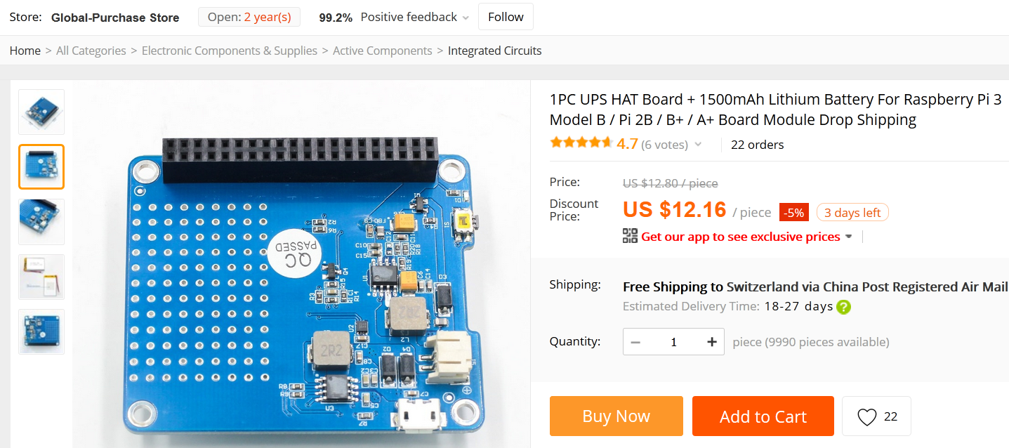
AliExpress UPS HAT Board
There is not much documentation about it available.

1500mAh Battery
There are no schematics, but I Simon (https://brousant.nl/jm3/elektronica/104-geekworm-ups-for-raspberry-pi) has reverse engineered the board:
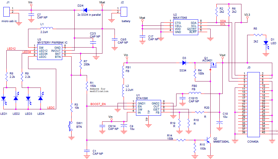
geekworm-ups Schematics (Source: https://brousant.nl/jm3/elektronica/104-geekworm-ups-for-raspberry-pi)
The board includes a step-up converter plus the Maxim 17048 battery charge status device, connected to the I²C bus.
tinyK22 Raspberry Pi HAT
At two lecture modules at the Lucerne University we are using a HAT on top of the Raspberry Pi, running with a NXP Kinetis K22 (tinyK22). The microcontroller is connected to the I²C bus of the Raspberry Pi. Below is the Rev3 schematics (we are using the Rev4 already), and for next semester we plan for a Rev5 with more features.

tinyK22_Raspy_Hat

tinyK22 Raspberry Pi HAT
Raspberry Pi Overlays
With the wiringPi libraries installed, the
$ gpio readall
produces a nice pin map of the Raspberry Pi header:
+-----+-----+---------+------+---+---Pi 3+--+---+------+---------+-----+-----+
| BCM | wPi |   Name  | Mode | V | Physical | V | Mode | Name    | wPi | BCM |
+-----+-----+---------+------+---+----++----+---+------+---------+-----+-----+
|     |     |    3.3v |      |   |  1 || 2  |   |      | 5v      |     |     |
|   2 |   8 |   SDA.1 |   IN | 1 |  3 || 4  |   |      | 5v      |     |     |
|   3 |   9 |   SCL.1 |   IN | 1 |  5 || 6  |   |      | 0v      |     |     |
|   4 |   7 | GPIO. 7 |   IN | 1 |  7 || 8  | 1 | ALT5 | TxD     | 15  | 14  |
|     |     |      0v |      |   |  9 || 10 | 1 | ALT5 | RxD     | 16  | 15  |
|  17 |   0 | GPIO. 0 |   IN | 0 | 11 || 12 | 0 | IN   | GPIO. 1 | 1   | 18  |
|  27 |   2 | GPIO. 2 |   IN | 0 | 13 || 14 |   |      | 0v      |     |     |
|  22 |   3 | GPIO. 3 |   IN | 0 | 15 || 16 | 0 | IN   | GPIO. 4 | 4   | 23  |
|     |     |    3.3v |      |   | 17 || 18 | 0 | IN   | GPIO. 5 | 5   | 24  |
|  10 |  12 |    MOSI |   IN | 0 | 19 || 20 |   |      | 0v      |     |     |
|   9 |  13 |    MISO |   IN | 0 | 21 || 22 | 0 | IN   | GPIO. 6 | 6   | 25  |
|  11 |  14 |    SCLK |   IN | 0 | 23 || 24 | 1 | IN   | CE0     | 10  | 8   |
|     |     |      0v |      |   | 25 || 26 | 1 | IN   | CE1     | 11  | 7   |
|   0 |  30 |   SDA.0 |   IN | 1 | 27 || 28 | 1 | IN   | SCL.0   | 31  | 1   |
|   5 |  21 | GPIO.21 |   IN | 1 | 29 || 30 |   |      | 0v      |     |     |
|   6 |  22 | GPIO.22 |   IN | 1 | 31 || 32 | 0 | IN   | GPIO.26 | 26  | 12  |
|  13 |  23 | GPIO.23 |   IN | 1 | 33 || 34 |   |      | 0v      |     |     |
|  19 |  24 | GPIO.24 |   IN | 1 | 35 || 36 | 0 | IN   | GPIO.27 | 27  | 16  |
|  26 |  25 | GPIO.25 |   IN | 1 | 37 || 38 | 0 | IN   | GPIO.28 | 28  | 20  |
|     |     |      0v |      |   | 39 || 40 | 0 | IN   | GPIO.29 | 29  | 21  |
+-----+-----+---------+------+---+----++----+---+------+---------+-----+-----+
| BCM | wPi |   Name  | Mode | V | Physical | V | Mode | Name    | wPi | BCM |
+-----+-----+---------+------+---+---Pi 3+--+---+------+---------+-----+-----+
With
$ gpio -v
I can verify the version. I have the V2.50 version installed:
gpio version: 2.50
Copyright (c) 2012-2018 Gordon Henderson
This is free software with ABSOLUTELY NO WARRANTY.
For details type: gpio -warranty

Raspberry Pi Details:
  Type: Pi 3B+, Revision: 03, Memory: 1024MB, Maker: Sony
  * Device tree is enabled.
  *--> Raspberry Pi 3 Model B Plus Rev 1.3
  * This Raspberry Pi supports user-level GPIO access.
For the Raspberry Pi exists the concept of ‘overlay’ commands. From the documentation:
Name:   gpio-poweroff
Info:   Drives a GPIO high or low on poweroff (including halt). Enabling this
        overlay will prevent the ability to boot by driving GPIO3 low.
Load:   dtoverlay=gpio-poweroff,=
Params: gpiopin              GPIO for signalling (default 26)

        active_low           Set if the power control device requires a
                             high->low transition to trigger a power-down.
                             Note that this will require the support of a
                             custom dt-blob.bin to prevent a power-down
                             during the boot process, and that a reboot
                             will also cause the pin to go low.
        input                Set if the gpio pin should be configured as
                             an input.
With this Pin it can be signalled that the shutdown of the Linux system is completed.
There is another pin overlay to trigger a power down:
Name:   gpio-shutdown
Info:   Initiates a shutdown when GPIO pin changes. The given GPIO pin
        is configured as an input key that generates KEY_POWER events.
        This event is handled by systemd-logind by initiating a
        shutdown. Systemd versions older than 225 need an udev rule
        enable listening to the input device:

                ACTION!="REMOVE", SUBSYSTEM=="input", KERNEL=="event*", \
                        SUBSYSTEMS=="platform", DRIVERS=="gpio-keys", \
                        ATTRS{keys}=="116", TAG+="power-switch"

        This overlay only handles shutdown. After shutdown, the system
        can be powered up again by driving GPIO3 low. The default
        configuration uses GPIO3 with a pullup, so if you connect a
        button between GPIO3 and GND (pin 5 and 6 on the 40-pin header),
        you get a shutdown and power-up button.
Load:   dtoverlay=gpio-shutdown,=
Params: gpio_pin                GPIO pin to trigger on (default 3)

        active_low              When this is 1 (active low), a falling
                                edge generates a key down event and a
                                rising edge generates a key up event.
                                When this is 0 (active high), this is
                                reversed. The default is 1 (active low).

        gpio_pull               Desired pull-up/down state (off, down, up)
                                Default is "up".

                                Note that the default pin (GPIO3) has an
                                external pullup.
The overlays get specified in ‘/boot/config.txt’:
$ sudo /boot/config.txt
and I have following added to it:
# Pin goes HIGH after a power down:
dtoverlay=gpio-poweroff,gpiopin=21

# Pulling pin down performs a shutdown:
dtoverlay=gpio-shutdown,gpio_pin=4,gpio_pull=up
With this I can use Pin 4 to request a power down and Pin 21 goes to HIGH after the power down.
Boot UART Login Console
The tinyK22 HAT has another feature: it acts as a USB-2-UART bridge between the Raspberry Pi. For this the NXP K22 reads and writes to the UART connected to the Raspberry Pi and interfaces with the Host PC using the OpenSDA USB CDC bridge.
To enable the boot login console on the Raspberry Pi, add the following line to the ‘/boot/config.txt’:
enable_uart=1
With this I have a login console to the Raspberry Pi, very useful if there is no Ethernet or WLAN configured:
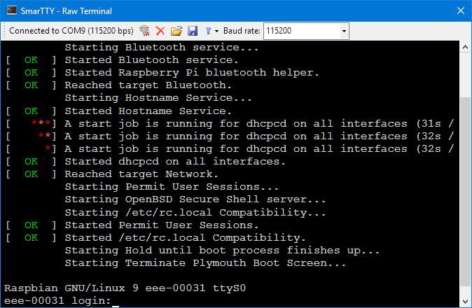
Boot Login Console
Firmware
The firmware is written in C with FreeRTOS running and using the NXP MCUXpresso IDE and MCUXpresso SDK:
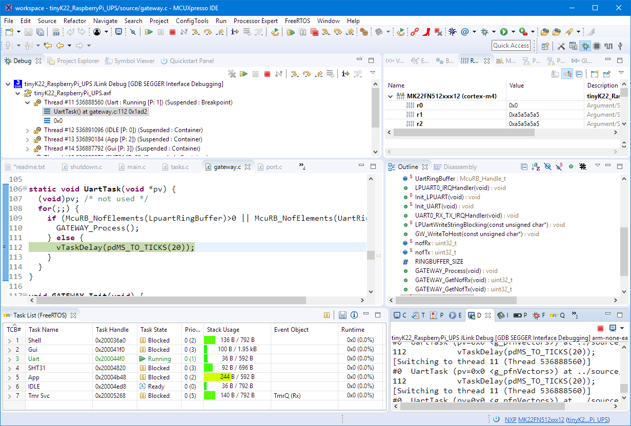
Debugging Firmware with MCUXpresso IDE
The HAT includes a socket for a SSD1306 I²C display (128×64 pixels). The application uses the LittevGL open source GUI with buttons, menus and graphs:

Battery Voltage and State of Charge
The HAT includes the SHT31 temperature and humidity sensor:

SHT31 Graph
With the menu and dialog a power down can be requested:

Dialog to powerdown Raspberry Pi
If the battery voltage indicates a discharging and the state of charge goes below 20%, the tinyK22 will automatically request a power down of the Raspberry Pi.
And yes: the firmware even includes the ‘Flying Toaster‘ screensaver 🙂

Flying Toaster Screensaver
Summary
I have now a way to cover for a short power out, and the 1500 mA lasts for about one hour. With the tinyK22 (NXP Kinetis K22FN512) I have user interface and OLED display to monitor the battery status and the other sensors, and the tinyK22 can properly power down the Linux system. In case of a power outage, the tinyK22 monitors the battery state of charge and can power down the Raspberry when the battery charge goes down too much. Currently it is not yet a true UPS as the tinyK22 is not able to automatically start the Raspberry Pi after a shutdown. But this is something which shall be supported in the next revision of the board.
You can find the Eclipse/MCUXpresso project sources on GitHub.
Happy UPSing 🙂
Links
- MCUXpresso IDE project: https://github.com/ErichStyger/mcuoneclipse/tree/master/Examples/MCUXpresso/tinyK22/tinyK22_RaspberryPi_UPS
- Rasperry Pi UPS HAT Board: http://www.raspberrypiwiki.com/index.php/Raspi_UPS_HAT_Board
- TinyK22: First tinyK22 Board with NXP K22FN512 ARM Cortex-M4F

I do like your approach. If I were asked to design a system to keep the micro SD card from becoming corrupted on unexpected power-downs, I would have simply used a supercapacitor to hold the RPi’s power rail high long enough for the RPi to complete a shutdown, with an analog comparator to assert the GPIO power-down pin if the source power dropped below a safe level.
But then I wouldn’t get the flying toasters! 🙂
LikeLike
Yes, the flying toasters were definitely the main criteria :-). We are using this board in our courses, and there we had the need to connect to the Raspberry Pi to find out its initial IP address. With most new laptops not having a physical ethernet port this was very painful plus required a Bonjour service running. With adding the ARM Cortex-M4 have have tons of extra capabilities, including a login shell, with the microcontroller doing the UART gateway (which has to be implemented by the students): lots of good content that way: ARM interrupts, ring buffers, reentrancy, FreeRTOS, queues, tasks, … 🙂
LikeLike
It’s interesting to note that some of yesteryear’s mainframes used minicomputers as front-end controllers / monitors — the DEC KL10 with a PDP-11 is one such example. And though I haven’t checked, I would guess that your RPi with an ARM Cortex-M4 front-end controller / monitor have roughly comparable processing power. What goes around comes around…
LikeLike
Clearly things are coming back in some way. Many of the newer cores running Linux have a built-in Cortex-Mx which helps to deal with realtime requirements or simply acting as a kick-on/off engine to kick the big brother 🙂
LikeLike
Hi Erich – Looks nice! Some questions…
1) Can the Pi tell the UPS to power off (last step in shutdown, to save battery charge when Pi desires shutdown)?
2) Are you going to combine all the pieces into a nice single board?
Thanks,
Best Regards, Dave
LikeLike
Hi Dave,
1) no, this is currently not possible.
2) probably not. I would like to keep the board with the battery/charger as is, because I don’t see right now a reason to re-do that one.
LikeLike
Pingback: Steampunk Lasercut Enclosure for Raspberry Pi | MCU on Eclipse
Pingback: Behind the Canvas: Making of “60 Billion Lights” | MCU on Eclipse