
The LPC55S69-EVK board comes on-board debug probe. The board includes the LPC4322JET100 device which acts like NXP LPC-Link2 debug probe:
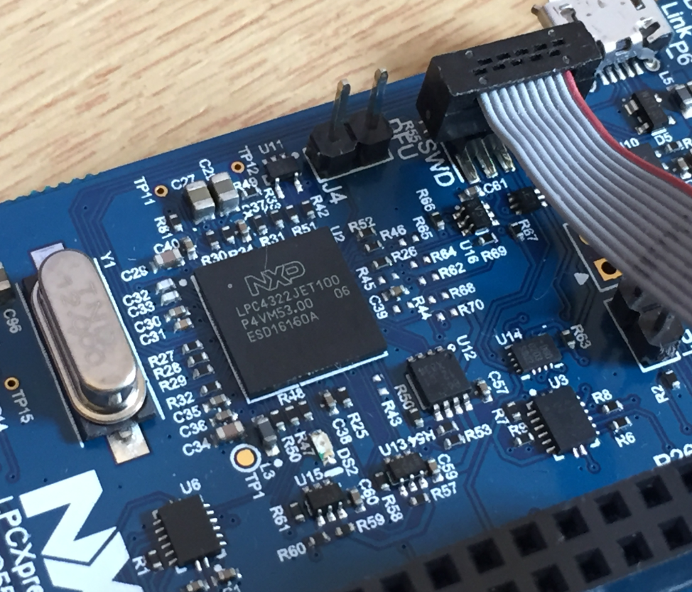
LPC4322JET100 on LPC55S69-EVK
But it is easily possible to use the board with an external debug probe or re-program the onboard one as a SEGGER J-Link debug probe.
Compared to the NXP OpenSDA circuit on other boards (Freedom, Tower) this is a much more powerful and faster debug interface. While the LPC-Link2 circuit can be found embedded on evaluation boards, it is available for $20 as a standalone probe.
External Debug Probes
The board features a standard 10-pin ARM SWD/JTAG header: without any extra jumper settings, it is possible to attach an external debug probe of choice, e.g. a SEGGER J-Link, a NXP LPC-Link2 or P&E Multilink.

Debugging with P&E Multilink Universal FX

Debugging with SEGGER J-Link EDU Mini

Debugging with external LPC-Link2
Reprogramming the NXP LPC-Link2 as SEGGER J-Link
As another option it is possible to use the on-board (or off-board) LPC-Link2 as a SEGGER J-Link (https://www.segger.com/products/debug-probes/j-link/models/other-j-links/lpc-link-2/).
💡 The steps described here apply for an external LPC-Link2 debug probe too. Keep in mind the SEGGER license agreement and that the firmware only allows debugging NXP LPC parts and no other devices).
- Download LPCScrypt from the NXP web site and run the installer. Remember the installation path (default for my version on Windows: C:\nxp\LPCScrypt_2.1.0_842)
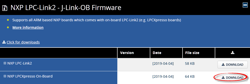
- Download the SEGGER NXP LPCXpresso On-Board Firmware from the SEGGER website (Note: for an external LPC-Link2 probe use the NXP LPC-Link2 file)

SEGGER NXP LPCXpresso On-Board Firmware
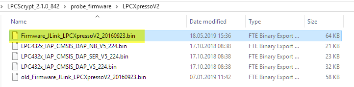
- The downloaded firmware file is named ‘Firmware_JLink_LPCXpressoV2.bin’. Place that file into the installation directory of the installed LPCScrypt:
<lpcscrypt>\probe_firmware\LPCXpressoV2 - The above directories already contain an (older) version of the firmware. Make sure that the new SEGGER firmware file matches the name of the already installed ones:
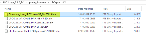
Renamed firmware files
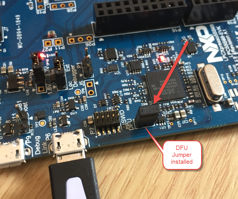
- Power the board with the DFU (Device Firmware Update) Jumper installed.
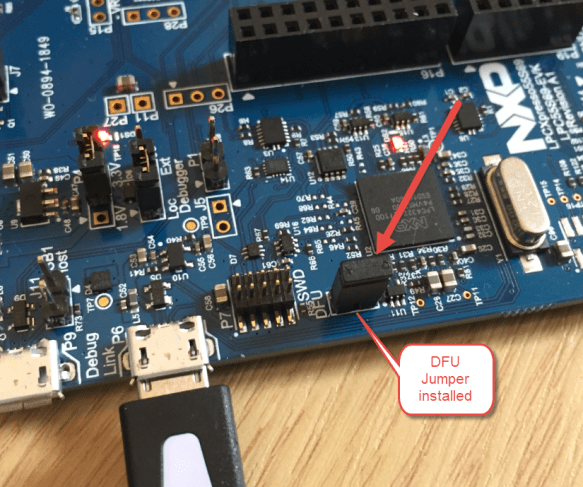
DFU Jumper Installed
- Run the script ‘program_JLINK.cmd’ located in the <install>\scripts folder:
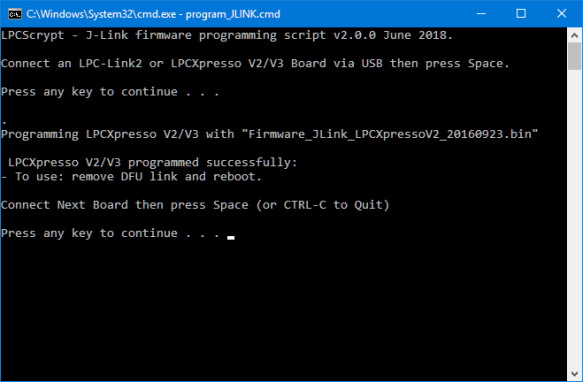
Running J-Link Script
- Remove the DFU jumper and re-power the board
- The board now has a J-Link on it 🙂

I can now use it as an external J-Link debug probe, e.g. from the MCUXpresso IDE. Having a J-Link gives the advantage of using SEGGER RTT or SEGGER SystemViewer.
💡 To reprogram the board back to the LPC-Link2/CMSIS-DAP firmware, run the ‘program_CMSIS.cmd’ batch file.
Summary
I like the fact that the board offers many different debug options: that way I can choose the one which fits best my needs (price, performance, features). Looking at the board/schematics it seems it would be possible to use the on-board probe debugging another board, but that would need at least soldering an SWD header. With the price of $20 for an external LPC-Link2 or a SEGGER J-Link EDU Mini I think this is not really worth the effort.
Happy Linking 🙂
Links
- LPC-Link2 Debug Probe: https://www.nxp.com/support/developer-resources/software-development-tools/lpc-developer-resources-/lpc-microcontroller-utilities/lpc-link2:OM13054
- P&E Multilink Universal Debug Probe: http://www.pemicro.com/multilink/
- SEGGER J-Link EDU Mini Debug Probe: https://www.segger.com/products/debug-probes/j-link/models/j-link-edu-mini/
- Load J-Link driver on a LPC-Link2: https://www.segger.com/products/debug-probes/j-link/models/other-j-links/lpc-link-2/
- LPCScrypt: https://www.nxp.com/support/developer-resources/software-development-tools/lpc-developer-resources-/lpc-microcontroller-utilities/lpcscrypt-v2.1.0:LPCSCRYPT?&tid=vanLPCSCRYPT
- SEGGER LPC-Link2 Firmware: https://www.segger.com/downloads/jlink/

Hi Erich,
Nice post! I want to know if you ever got instruction trace on this board through ETM or MTB. The documents state that the chip support ETM but it seems that there is no way to dump the instruction trace from the evaluation board. Missing ETB and trace pins? Any idea?
Thanks!
LikeLike
I have not (yet) used trace on that board.
LikeLike
Hi Erich !
Thank you for your post,
Do you remember having any issue when loading the firmware on the board through JLinkExe ?
Or did it needed special attention to the generated hex file ?
I’m using an NXP SDK with a GCC toolchain and it seems I can’t reliably boot (although I was able to flash the firmware on the board)
Best,
Ismail
LikeLiked by 1 person
Hi Ismail,
no, J-Link works fine for me, both with an external debug probe and as well using an on-board J-Link firmware (see https://mcuoneclipse.com/2021/04/05/debug-firmware-switching-for-the-lpc4322/).
Erich
LikeLike
Hi Erich !
Thank you for you answer !
Here’s how I generate an hex file for any example of the SDK :
arm-none-eabi-objcopy led_blinky.elf -O ihex led_blinky.hex
Here’s the current configuration I use to connect to the LPC55S69 board.
JLinkExe -device LPC55S69_M33_0 -if swd -speed 4000
>> connect
>> r
>> h
>> loadfile led_blinky.hex
>> r
>> g
I’ve tried both (external J-Link and on-board J-Link firmware) and unfortunately It seems that whenever I halt the processor using “halt” (in JLinkExe), the go command doesn’t seems to have any effect on the state of the processor.
Did I miss anything in terms how to debug and load any firmware ? The only way I can load any firmware at the moment is by using OZONE and even when I reset the board it seems stuck.
Best Regards,
Ismail
LikeLiked by 1 person
Have you tried using the MCUXpresso IDE and debugger to load the application? Because this is from NXP and works the best imho.
LikeLike
Hello ! I tried MCUXpresso IDE and it works as expected with the segger JLink.
As we’re not interested in using a specific IDE for developping we first use the ARM GCC SDK generated by NXP to discover it provides not working examples (even when using the checksum tool from MCUXpresso IDE).
Any example in your blog to work only with CLI tools and bare-metal sdk from NXP ?
Thank you very much for your help,
Ismail
LikeLiked by 1 person
Not sure what would be wrong with using an IDE, as it is basically just an editor? You can use anything you want, but somehow you need to write your code. At the minimum you need a text editor.
You do not have to use the IDE: simply take the source files and run them with make (the IDE has created all the make files for you). The most difficult part is to have all the correct files and settings, and the project created from the IDE is a prefect start.
Or simply use the cmake files present in the SDK. How this can work (e.g. command line on Linux), see https://mcuoneclipse.com/2019/04/14/tutorial-mcuxpresso-sdk-with-linux-part-1-installation-and-build/ where no IDE is involved.
Another consideration is running the project directly from make, see https://mcuoneclipse.com/2017/08/03/building-eclipse-and-mcuxpresso-ide-projects-from-the-command-line/
Or why not create your own cmake project? I’m using Visual Studio Code for this (see my series starting with https://mcuoneclipse.com/2021/05/01/visual-studio-code-for-c-c-with-arm-cortex-m-part-1/): what I do here is simply using Visual Studio Code as Editor (not in the sense of a builder), so this would be perfect for you too: the build is run externally with cmake using either make or even better ninja.
What environments like the MCUXpresso IDE brings to the table is a starting point with all the details of the setup solved for you. I recommend use this as the start, and then once you understand it you can change things as you want and need.
I hope this helps,
Erich
LikeLiked by 1 person
Hi Erich,
Thanks for the great article!
I am trying to use SEGGER’s Educational J-Link (https://www.segger.com/products/debug-probes/j-link/models/j-link-edu/) with the LPC55S69-EVK
Following an installation of J-Link’s gdb server, MCUXpresso successfully recognizes the SEGGER device and I am able to start a debug session on the LPC55S69-EVK.
However, there are only ‘stop’ and ‘pause’ buttons available through the debug session and no ‘step in’ ‘step over’ buttons displayed in MCUXpresso.
Trying to place HW breakpoint does not help either.
What am I missing???
(BTW, I also tried to flash Firmware_JLink_LPCXpressoV2_20190404.bin, however this is recognized as faulty firmware by MCUXpresso IDE as soon as I start debugging…then MCUXpresso IDE starts to re-flash the EVK with different firmware.)
Many thanks,
Arga
LikeLiked by 1 person
Hi Arga,
I’m using as well the SEGGER J-Link EDU with my LPC55S69-EVK, and it works for me with all the buttons (not sure why it would be different for you)?
>>Following an installation of J-Link’s gdb server, MCUXpresso successfully recognizes the SEGGER device and I am able to start a debug session on the LPC55S69-EVK.
Not sure what you mean with this: you do not have to install anything: everything is already provided with the MCUXpresso IDE installation which installs the Segger tools as needed. You don’t have to install the J-Link gdb server. All the J-Link probes are supported out of the box with the IDE. So maybe this is causing your problems?
>>BTW, I also tried to flash Firmware_JLink_LPCXpressoV2_20190404.bin,
As the board has an LPC4322 ad debug device, you need to use the LPCScrypt to program it, like in https://mcuoneclipse.com/2021/04/05/debug-firmware-switching-for-the-lpc4322/
You cannot directly flash an image, you need to follow the above process.
I hope this helps,
Erich
LikeLike