
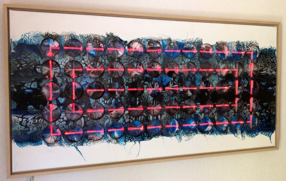
As promised I’m going to share more details about the “60 Billion Lights” project. It is about a project to build a piece of electronics behind a 100×50 cm canvas to show animations or to display information like temperature, humidity, weather, time or just any arbitrary text.

Writing text
This project is based on a series of earlier projects, see “DIY Stepper Motor Clock with NXP LPC845-BRK“, “World Stepper Clock with NXP LPC845” and “Copyright Law for Makers and Educators“. The articles shows the implementation details and how this is built. Additional details, links and fiels can be found in the ‘Links’ section at the end of this article.
Many have asked about that “60 Billion” number: ’60’ is for the number of units. The ‘Billion’ is about the number of combinations: 60 (units) * 2 (motors) * 360 (positions) * 256*256*256 (RGB colors) so actually it would be far more than 60 billion combinations. So more kind of a ball park number than exact science 😉
Lines
Motors
The motors used are special instrument cluster (automotive dashboard) motors: they are dual-shaft and have the end stops removed for a 360° rotation.

Stepper Motor
The original motor is the VID28.05. It is available as BKA30D R5 too.
BKA30E-R5
Below a video during evaluation of the motors:
It is possible to get the motors with the end stop removed by the factory: otherwise remove the end stop with a sharp knife:

VID28.05 End-Stop
As motor driver the AX12.017 is used: that IC is designed to drive such small stepper motors and supports micro-stepping with 4320 steps for each motor.

AXA12017 Motor Driver
The driver simplifies driving the motors (step and direction pins). With that driver the stepper motors are very silent: 120 motors moving the same time makes only a minimal noise, moving less than half of it is barely noticeable which is important to have it in the living room.
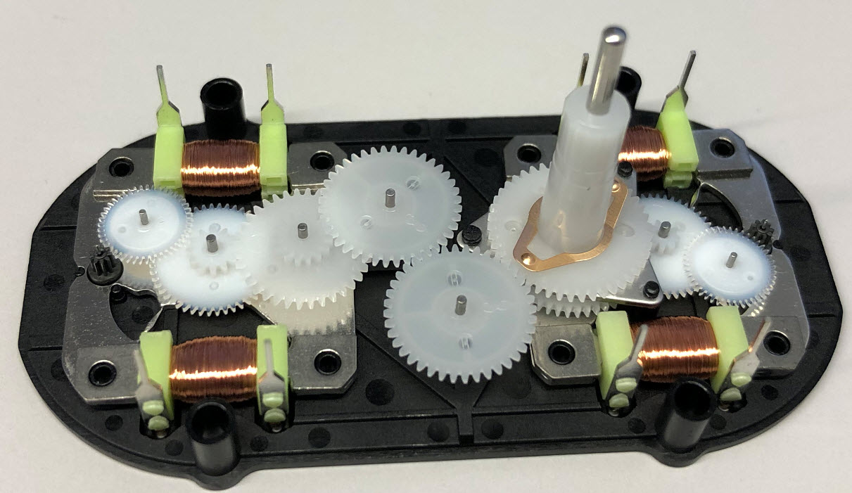
Motor PCB
4 Motors are combined on a single PCB:
- 4 dual shaft stepper motors (BKA30D R5), 4320 steps/revolution
- 2 Quad Stepper motor driver (AX1201728SG)
- 8 hall sensors (AHA3572) for zero detection
- 1 LPC845 microcontroller (ARM Cortex-M0+, 64KByte FLASH, 16 KByte RAM)
- 3.3V converter (XC6206P332MR-G)
- RS-485 interface (SN65HVD72DR) with solder jumper for 120 Ohm bus termination
- Status LED, debug connector, reset switch
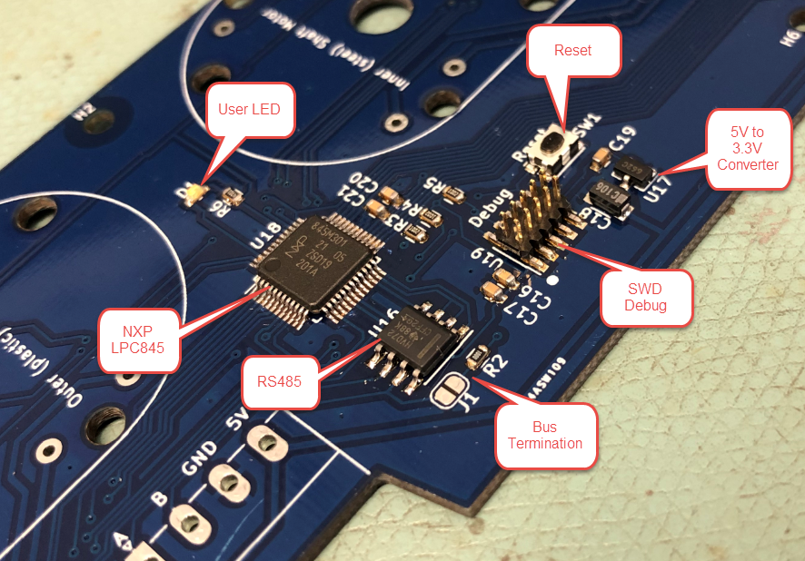
Board with Microcontroller

Board with Motors
The ‘front side includes sensors for a zero positioning:
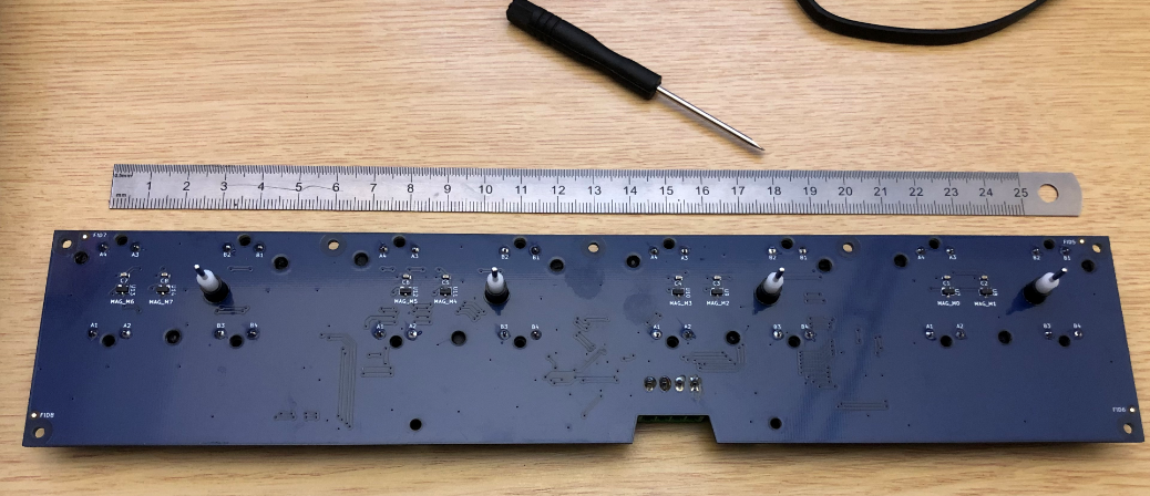
Clock Top Side
The sensors used are the AHA3572 which detect the magnetic field of small magnets on the hands.
💡 With the laser cut acrylic hands used in this build, the sensors are currently not used.

AHA3572
The PCBs have been populated with a modified Pick&Place machine (see “Retrofitting a Charmhigh CHM-T36VA Machine with OpenPnP“). After ‘baking’ it in the reflow oven they have been washed (without the motors!) using an ultrasonic washing machine to remove the flux:
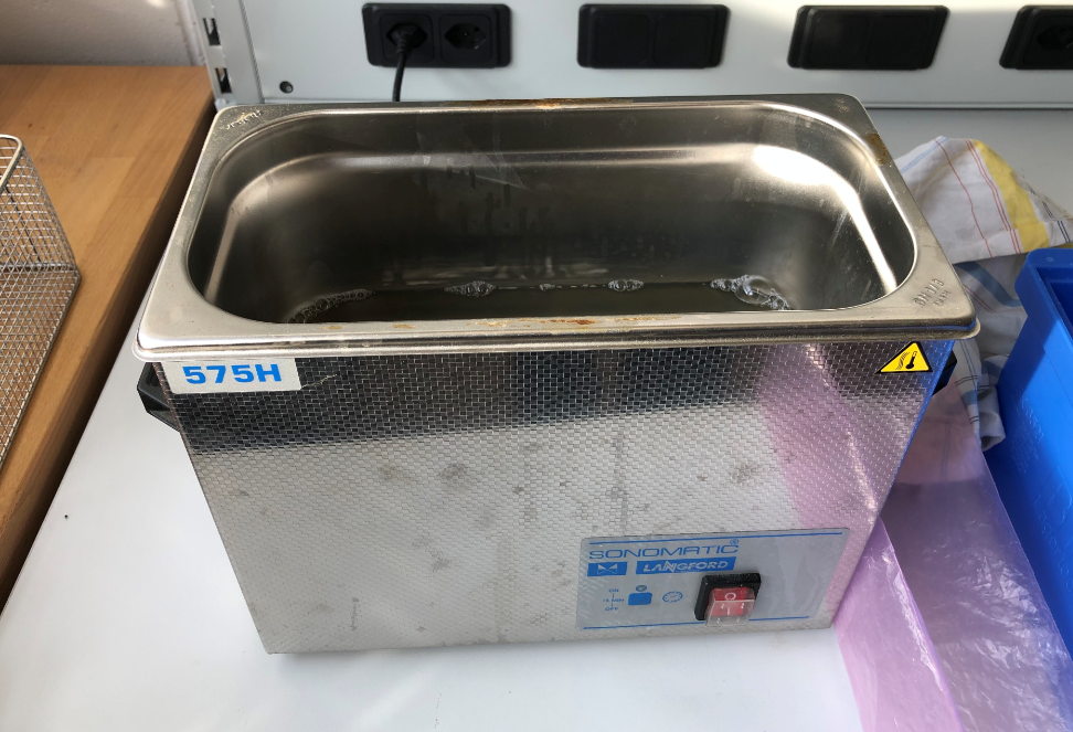
Sonomatic Ultrasonic Maschine

PCB in Ultrasonic Washing Machine
LED Rings
To create the ‘special’ effect, each motor has added 40 WS2812B RGB LEDs with DMA. The concept has been tested with normal WS2812B LED stripes:

Test with Standard WS2812B
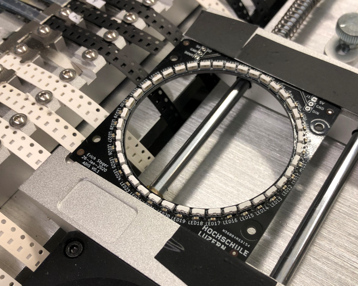
But wiring would have been difficult. To have more LEDs and better illumination a ‘side’ version of the WS2812B has been used and a board created for it.

WS2812B-SIDE Board

LED Ring
For first two LED rings were used for each unit:
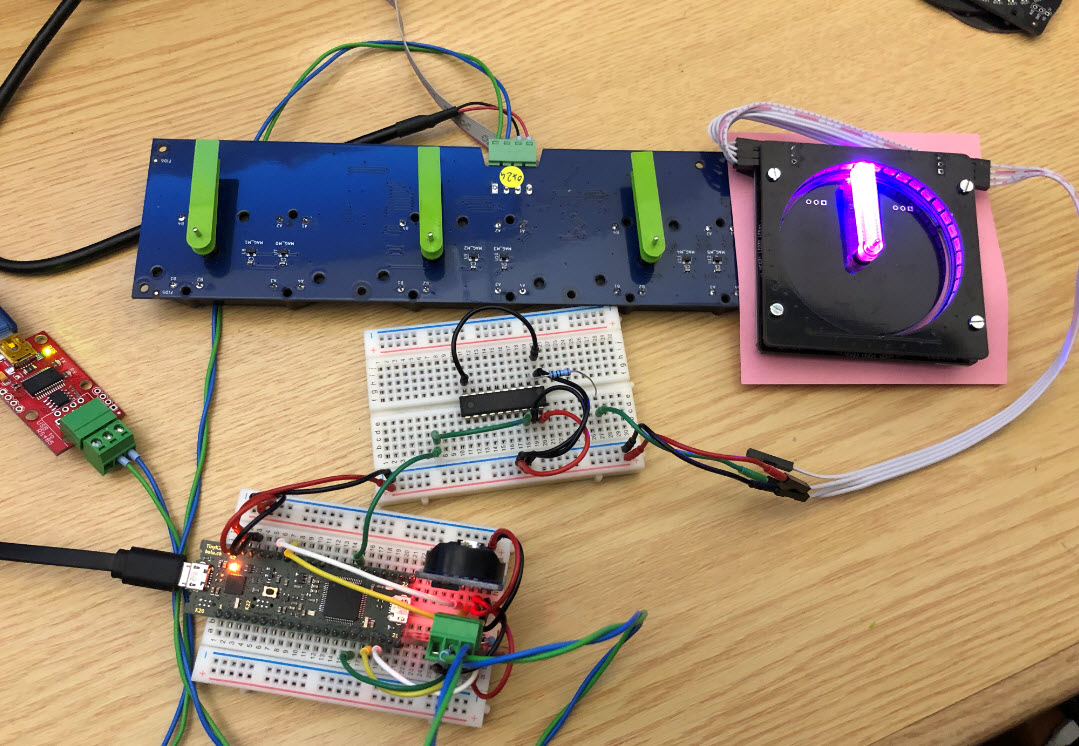
LED Test with tinyK22
Tests showed that one LED ring would be enough, so the final design uses one ring for each unit.
The LED board could be mounted bottom-side or top-side:

LEDs on top
The final design uses them in the ‘down’ orientation, mainly to have a flat surface to the front.
LED Boards Bottom Orientation
The populating the rings a modified CHMT PnP machine with OpenPnP has been used. A stencil is used to apply the solder paste:

Stencil
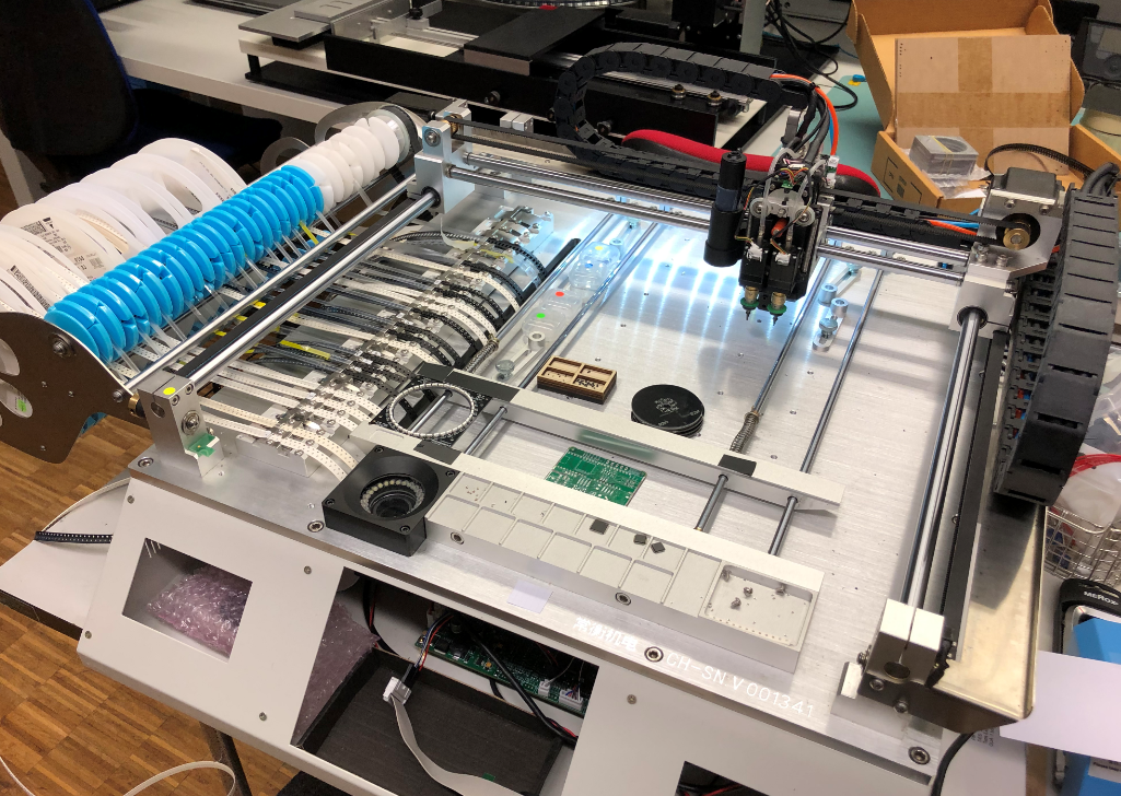
CHMT Pick and Place Machine running OpenPnP
assembled LED ring
Below is a video with the machine in action (not optimized for speed at that time):
The populated rings then get ‘baked’ in the reflow oven:
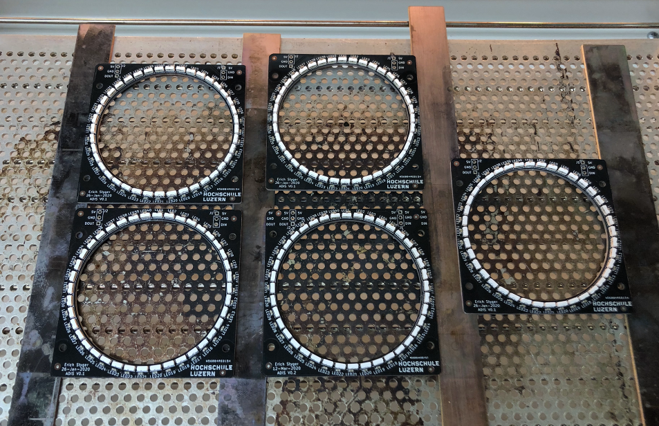
Rings out of the reflow oven
Connectors
90° angled standard 2.54mm headers are used as connectors for the boards.
Board Connectors
For a low profile on the bottom side, the pins have been cut to keep the surface as flat as possible:

Clipped Connector Pins
Space to connect the boards is tight. To connect the boards, the first attempt was to use individual pins:
- file down one side to get a pipe and remove the plastic
- Use the other side of the pin and cut down the pin end to about 0.1 mm
- Stick them together and solder them
- put shrink tube around it

Ring Board Connectors

first connector
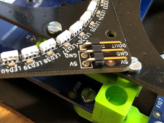
That was a lot of work and was not reliable enough. A new version used a set of pins together, and this worked well:

Soldered Connector

connectors

Connected Boards
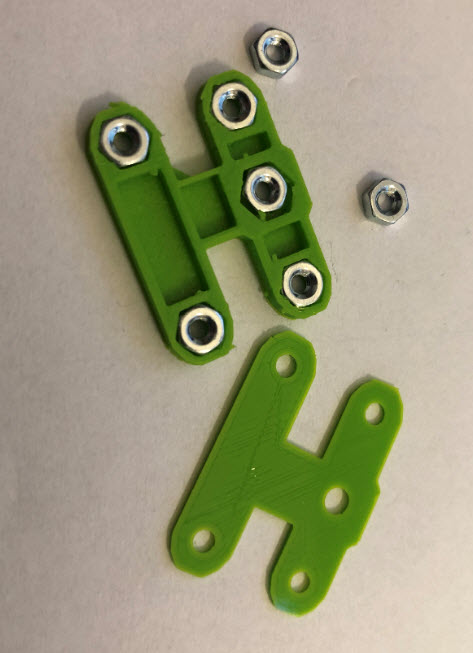
Panel Holders
The ring boards get connected with 3D printed connectors and distance holders.
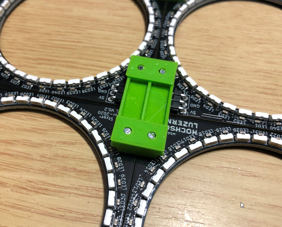
Board Connector 3D Printed
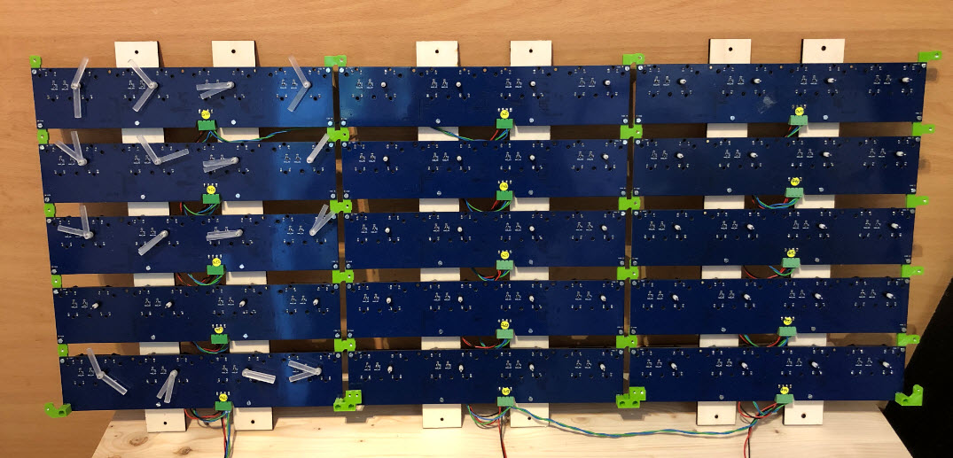
Below the bottom side:

Ring Boards connected
This is how it looks from the top:

Ring Boards Top side
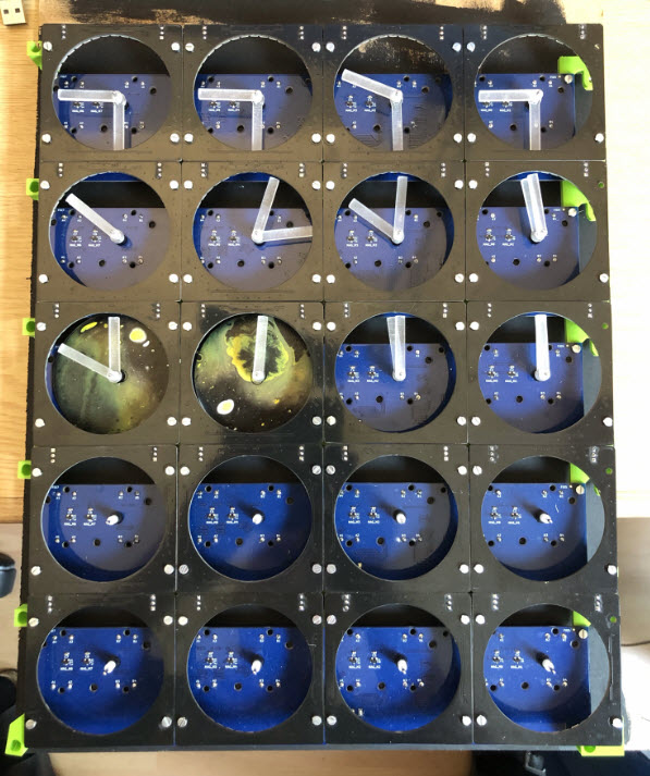
In a similar way, 3D printed holders and spacers are used to connect the stepper motor boards:
Motor Board Connector
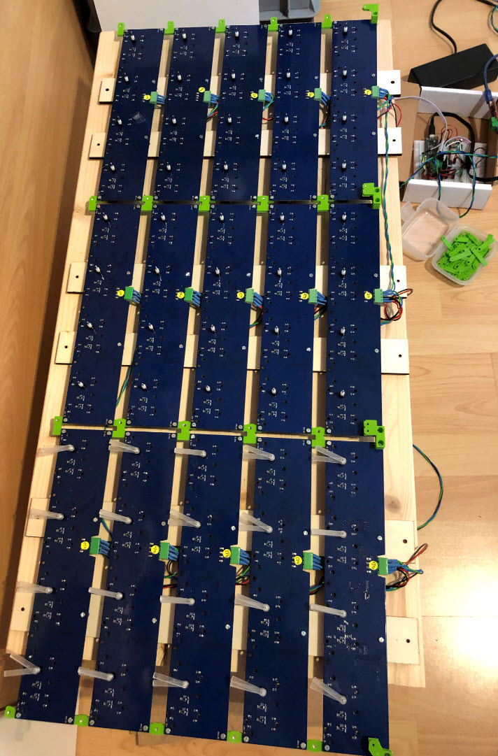
Connected Stepper Boards
The back of the stepper boards is hold together with 4 mm laser-cut plywood:

Stepper board back with plywood
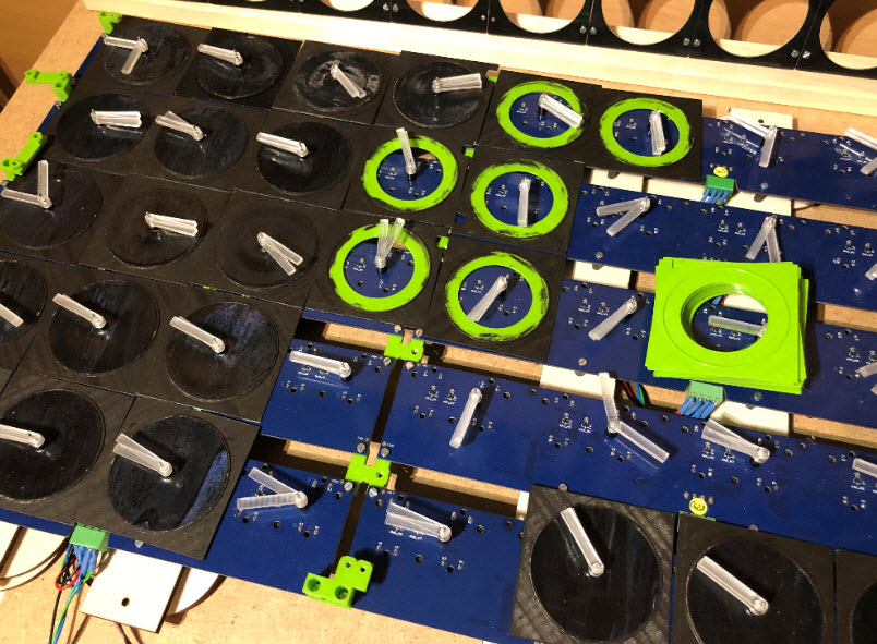
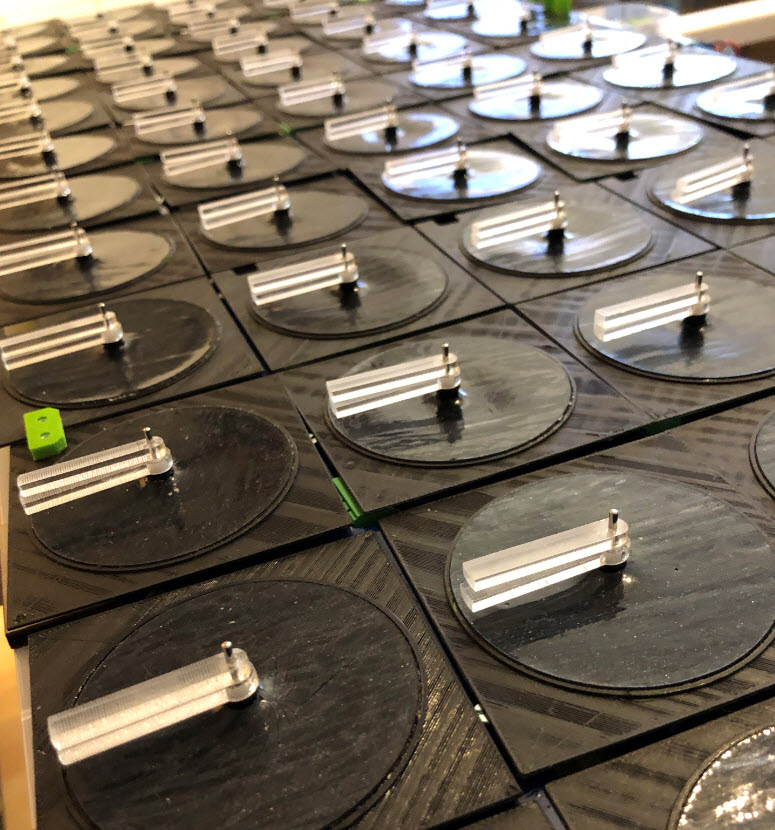
Front with Stepper Boards

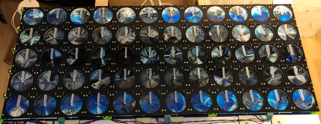
All 60 boards

Powered Boards
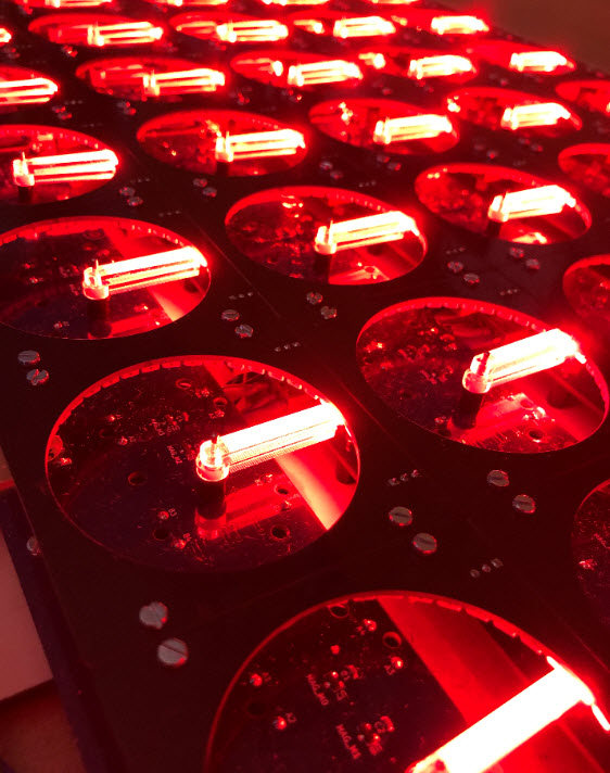
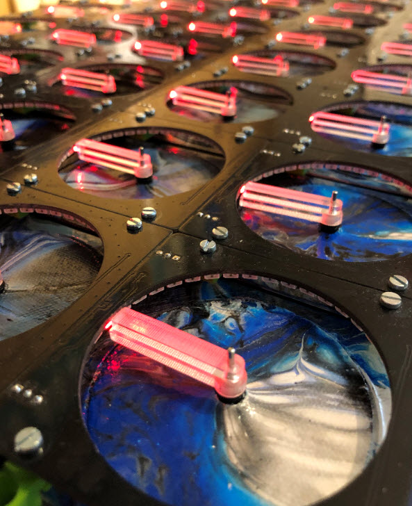
Red Light Test
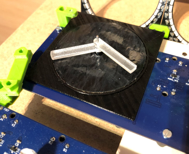
Hands
To minimize motor noise it is important that the hands have good contact to the motor outer and inner shaft. To have the two hands as close as possible together, a simple 3D printed spacer is placed below the lower hand. That helps to get the acrylic on the right height for the LEDs too.
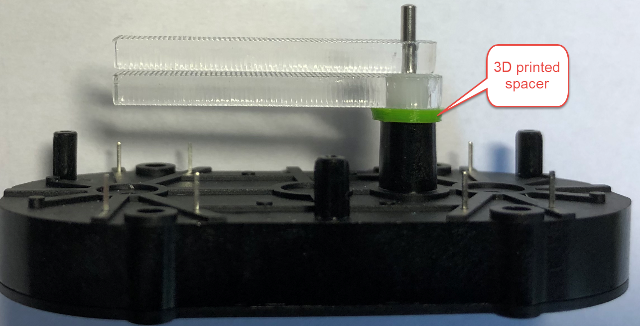
3d printed motor spacer
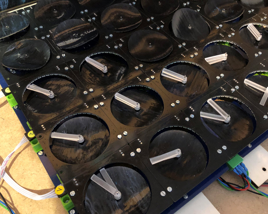
The inititial design used two hands of equal length. As this was limiting to write text, the lower hand has been extended.That way the hands can form a ‘T’:

Humidity Display
They are laser-cut from 3 mm PMMA, laser-engraved on top and bottom side for a good visual effect.

Extended Hand
Extended Hand Illuminated
Master
The boards are connected on a RS-485 bus. They can be controlled directly by the host PC using a USB converter from Sparkfun (SparkFun RS485 breakout board):
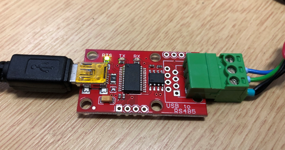
SparkFun RS-485 USB Converter with connector
Another way is to use a breadboard solution using the NXP LPC845-BRK board, together with the SparkFun RS485 breakout board.
To test the clock, the NXP LPC845-BRK board was used, together with the SparkFun RS485 breakout board.

Test Board with NXP LPC845-BRK
The breakout board needs to be modified (failsafe mode) with a 1K pull-up (line A) and 1K pull-down (line B).
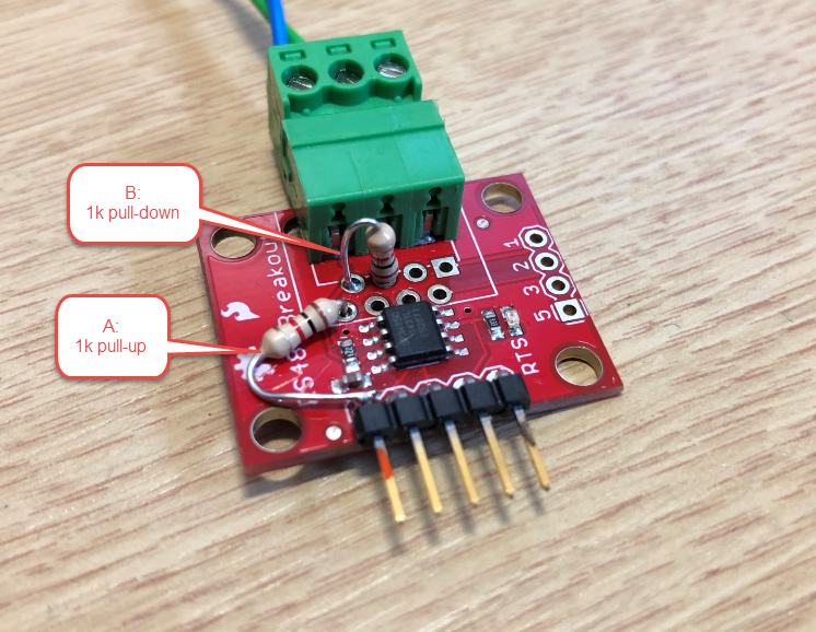
SparkFun RS-485 Breakout Board with Pull-Up and Pull-Down
To combine everything including drivers for the LEDs, a simple breakout board has been created which can be put behind the canvas:

tinyK22 Master Board
- Using tinyK22 board (Kinetis K22FN512) with DMA to drive all the WS2812B LEDs
- Adafruit BLE SPI Friend
- Adafruit Ambient Light Sensor (TSL2561) with optional socket for Adafruit TSL2591 (bottom of board)
- ESP32 connector (bottom of board)
- DS3232 RTC with backup battery
- Sensirion SHT30 temperature/humidity sensor (see “Building a Raspberry Pi UPS and Serial Login Console with tinyK22 (NXP K22FN512)“)

tinyK22 Master Board Reflow

tinyK22 master board
The board is used for power distribution (up to 6A@5V) and acts as RS-485 master on the bus, so in charge for everything.
Software
The software has been developed with the Eclipse based NXP MCUXpresso IDE and SDK using GNU tools. In addition to the SDK, the McuLib was used for lower and higher level drivers, including a port of FreeRTOS. The firmware fits into the 64 KByte of FLASH and 16 KByte of RAM.
The Pins tool is used to find optimal pin assignments and to ease the routing on the PCB:
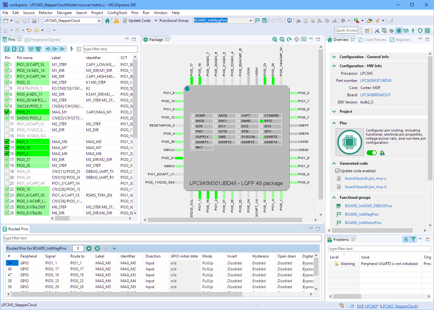
MCUXpresso IDE Pin Assignment Tool
To reduce the components on the board, I’m running the LPC845 from its internal clock:
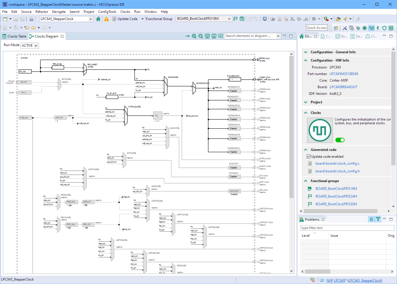
MCUXpresso IDE with Clock configuration
Debugging the boards is done with SEGGER J-Link EDU mini, and with this I have a CLI with the RTT available:

SEGGER RTT Interface and CLI
For each stepper motor there is information kept about the driver, including the current position, programmable delay/speed. And each stepper motor maintains a queue of vector commands to be executed:
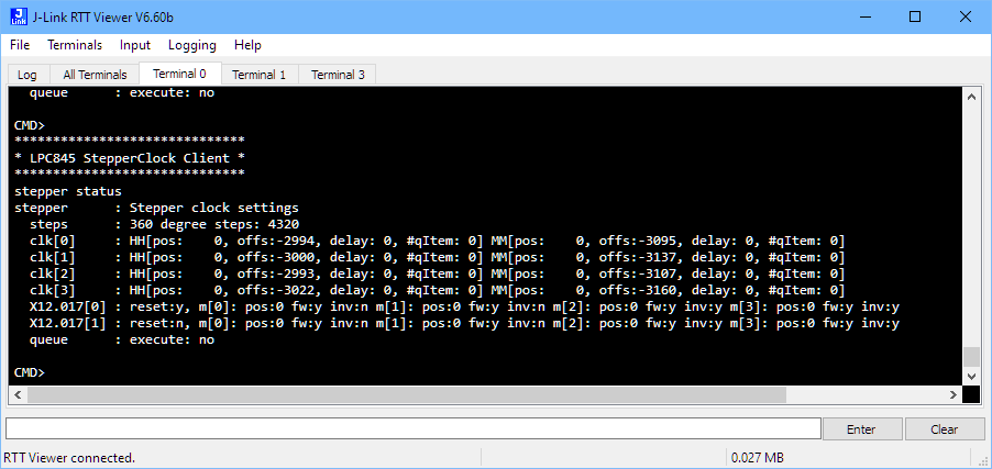
StepperClockStatus
The stepper motor driver includes a self-calibrating and automatic zero position finding using magnets if enabled. The offsets are stored in the LP845 NVMC:
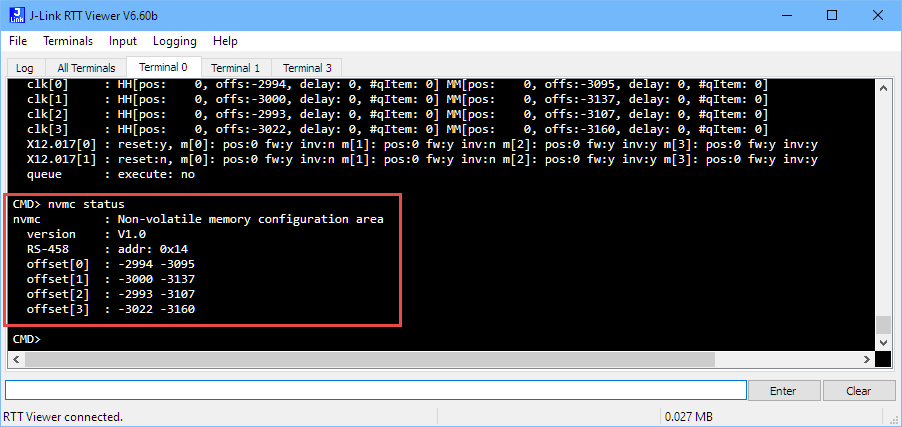
Configuration in Non-Volatile Memory
The motors and driver operates at a stepper frequency of 5 kHz (one step every 200 us), with a configurable acceleration and decay curve: that way the motors and hands accelerate slowly and slow down which is not only nicer to watch but also greatly reduces stepper noise from the internal gears.
The stepping of the motors is completely handled with a timer interrupt. Because the LPC845 has not enough timer channels, everything is done in a single channel.
The interrupt priorities need special attention (see ARM Cortex-M, Interrupts and FreeRTOS):
static void Timer_Init(void) {
  uint32_t eventNumberOutput = 0;
  sctimer_config_t sctimerInfo;
  uint32_t matchValue;
  status_t status;

  SCTIMER_GetDefaultConfig(&sctimerInfo);
  SCTIMER_Init(SCT0, &sctimerInfo);
  matchValue = USEC_TO_COUNT(STEPPER_TIME_STEP_US, CLOCK_GetFreq(kCLOCK_CoreSysClk));
  status = SCTIMER_CreateAndScheduleEvent(SCT0, kSCTIMER_MatchEventOnly, matchValue, 0 /* dummy I/O */, kSCTIMER_Counter_L /* dummy */, &eventNumberOutput);
  if (status==kStatus_Fail || eventNumberOutput!=0) {
    for(;;) {} /* should not happen! */
  }
  SCTIMER_SetupCounterLimitAction(SCT0, kSCTIMER_Counter_L, eventNumberOutput);
  SCTIMER_SetCallback(SCT0, SCTIMER_Handler0, eventNumberOutput);
  SCTIMER_EnableInterrupts(SCT0, (1<<eventNumberOutput));
  NVIC_SetPriority(SCT0_IRQn, configLIBRARY_MAX_SYSCALL_INTERRUPT_PRIORITY+1); /* less urgent than RS-485 Rx interrupt! */
  EnableIRQ(SCT0_IRQn); /* Enable at the NVIC */
}
The interrupt handler clears the flag and calls a callback:
static void SCTIMER_Handler0(void) {
  uint32_t flags;

  flags = SCTIMER_GetStatusFlags(SCT0);
  if (flags & SCT_CHANNEL_MASK_0) {
    SCTIMER_ClearStatusFlags(SCT0, SCT_CHANNEL_MASK_0); /* Clear interrupt flag */
    MATRIX_TimerCallback();
  }
}
The interrupt calls a handler which updates all motors. The driver code updates the internal states and uses a custom speed-up (acceleration) and slow-down. Speed is controlled by a delay counter:
bool STEPPER_TimerClockCallback(STEPPER_Handle_t stepper) {
  STEPPER_Device_t *mot = (STEPPER_Device_t*)stepper;
  int n;

  if (mot->doSteps==0) {
    return false; /* no work to do */
  }
  if (mot->delayCntr!=0) { /* delay going on? */
    mot->delayCntr -= STEP_SIZE; /* decrement delay counter */
    return true; /* still work go do */
  }
  /* do the step */
  if (mot->doSteps > 0) { /* forward */
    n = STEP_SIZE; /* number of steps in one iteration */
  } else { /* backward */
    n = -STEP_SIZE;
  }
  mot->pos += n; /* update position */
  if (mot->stepFn!=NULL) { /* call driver */
    mot->stepFn(mot->device, n);
  }
  mot->doSteps -= n; /* update remaining steps */
  mot->delayCntr = mot->delay*STEP_SIZE; /* reload delay counter */

  /* check if we have to speed up or slow down */
  if (mot->speedup || mot->slowdown) {
    int32_t stepsToGo; /* where we are in the sequence */

    stepsToGo = mot->doSteps;
    if (stepsToGo<0) { /* make it positive */ stepsToGo = -stepsToGo; } if (mot->speedup && STEPS_TO_DEGREE(stepsToGo)>STEPPER_ACCELERATION_RANGE_DEGREE) { /* accelerate if we are starting up */
      if (STEPS_TO_DEGREE(mot->accelStepCntr)<=STEPPER_ACCELERATION_RANGE_DEGREE) { mot->accelStepCntr += STEP_SIZE; /* increase acceleration step counter position up to the cap value */
      }
      AccelDelay(mot, STEPS_TO_DEGREE(mot->accelStepCntr));
    } else if (mot->slowdown && STEPS_TO_DEGREE(stepsToGo)<STEPPER_ACCELERATION_RANGE_DEGREE) { /* slow down at the end */ if (mot->accelStepCntr>=0) {
        mot->accelStepCntr -= STEP_SIZE; /* decrease the current de-accleration counter down to zero */
      }
      AccelDelay(mot, STEPS_TO_DEGREE(mot->accelStepCntr));
    }
  } /* speed up or slow down */
  return true; /* still work to do */
}
To optimize the application for performance, the SEGGER SystemView was critical to find possible performance issues and keep the CPU usage low.

Segger SystemView
Canvas
An important part of the design is the canvas. So far two different ones have been produced, in two different ways:
- Paint the canvas first, then laser cut it.
- Laser cut the canvas first, then paint it
Both approaches work and have their pros and cons. Ideally the laser cutter would be big enough to cut the canvas in one step. But mine only has 40×40 cm cutting area which gave a challenge.
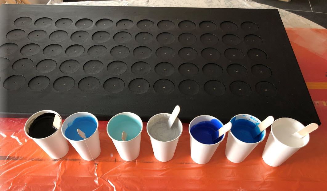
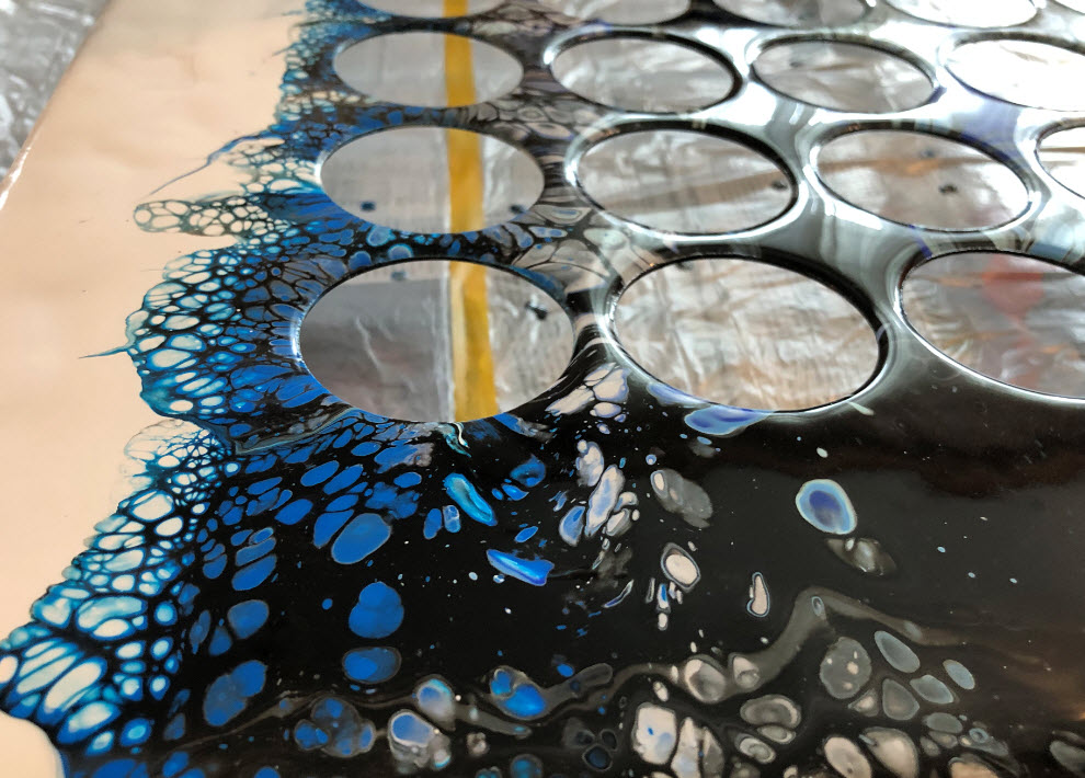
Painting is with a ‘acrylic pouring’: acrylic colors get mixed with water and a flow enhancement, added a few drops of silicon oil, then poured on the canvas.
The first one was produced in a ‘dark’ version:

Acrylic Colors
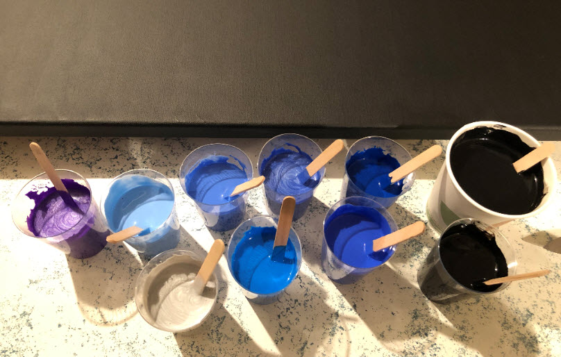
Mixed Colors
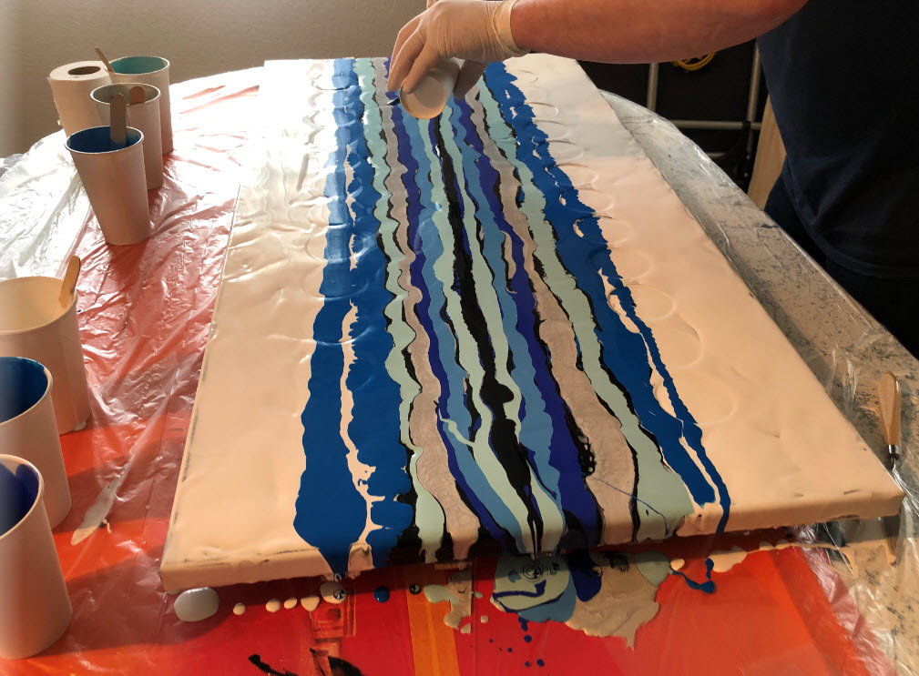
The paint gets on the canvas in stripes:
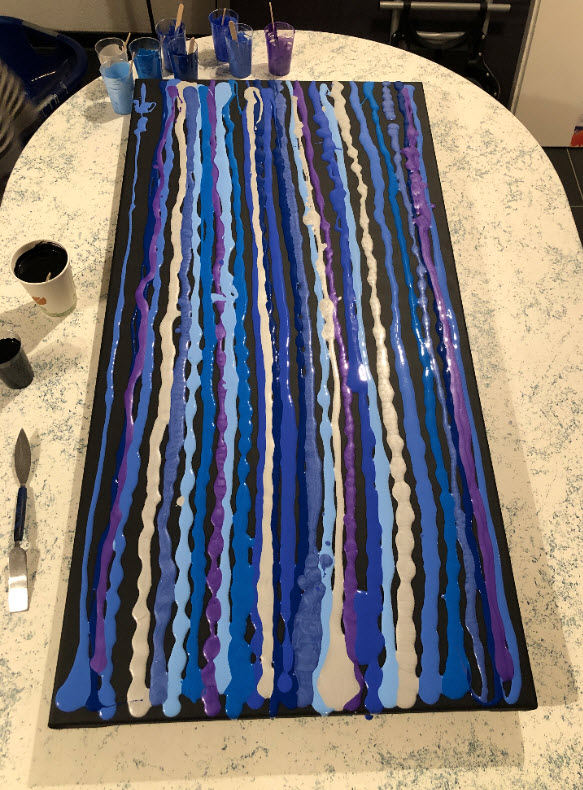
Colors on Canvas

Added Center Black
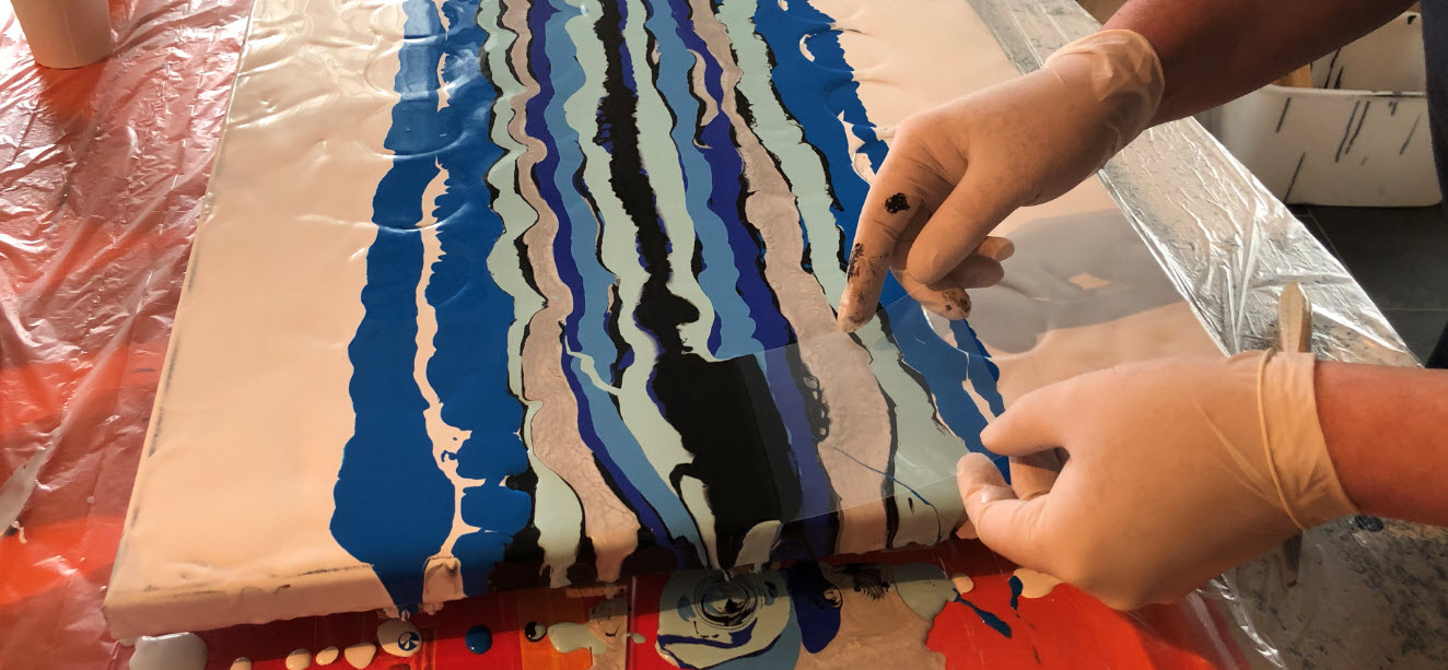
Using a cardboard the paints get distributed from left to the right:
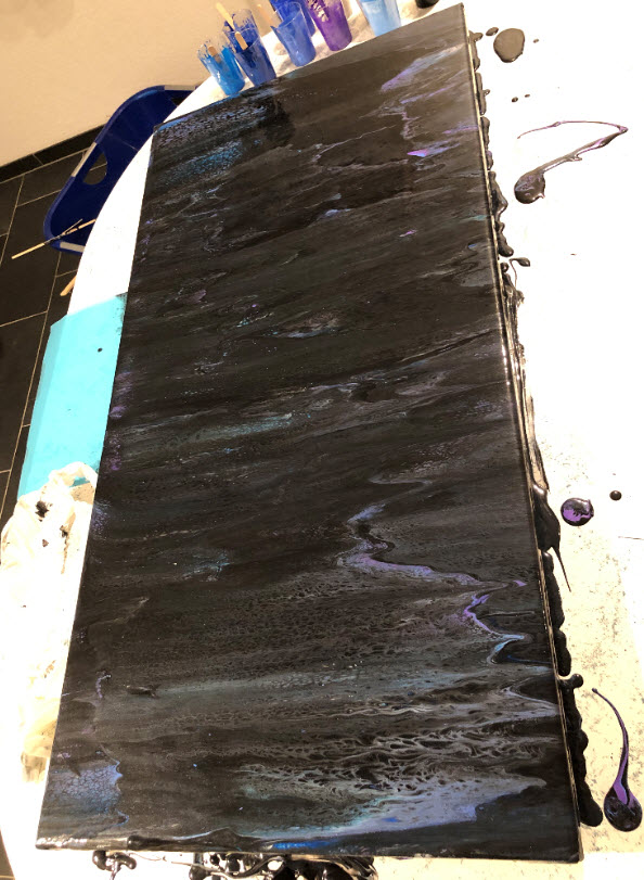
Swiped Colors
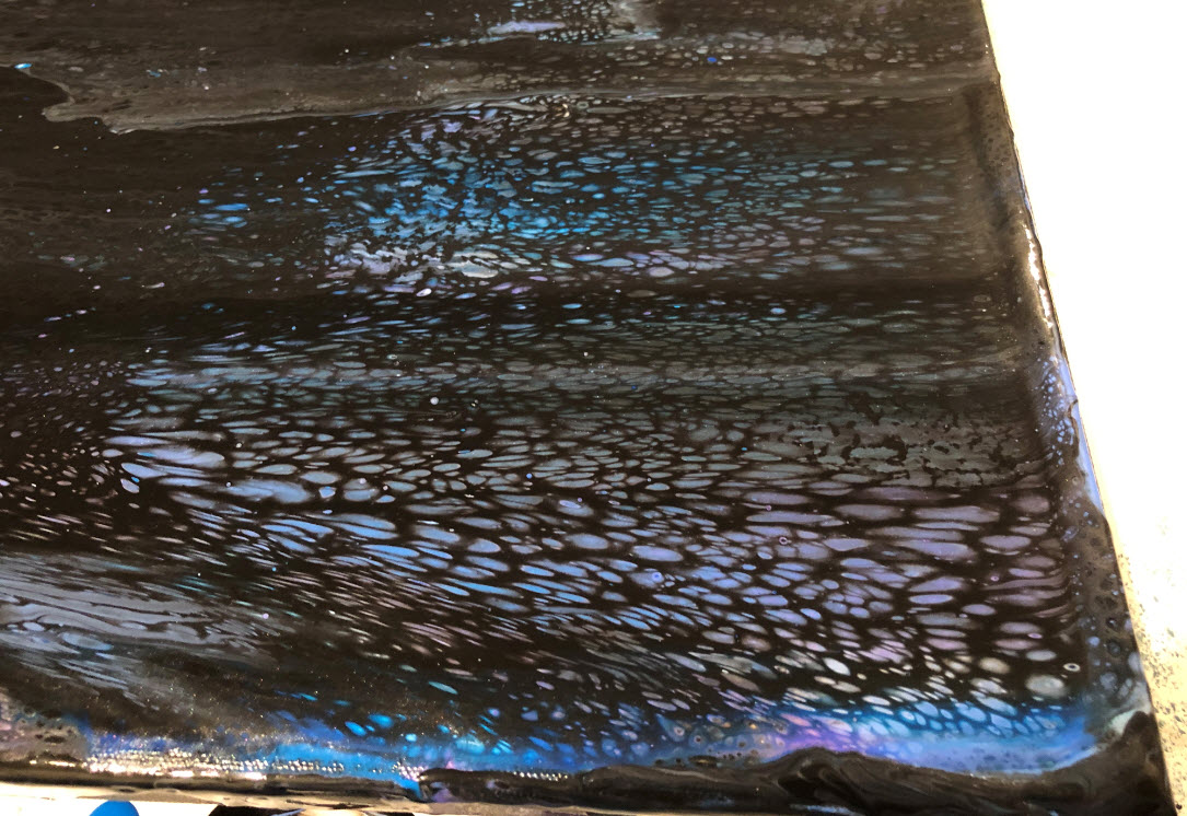
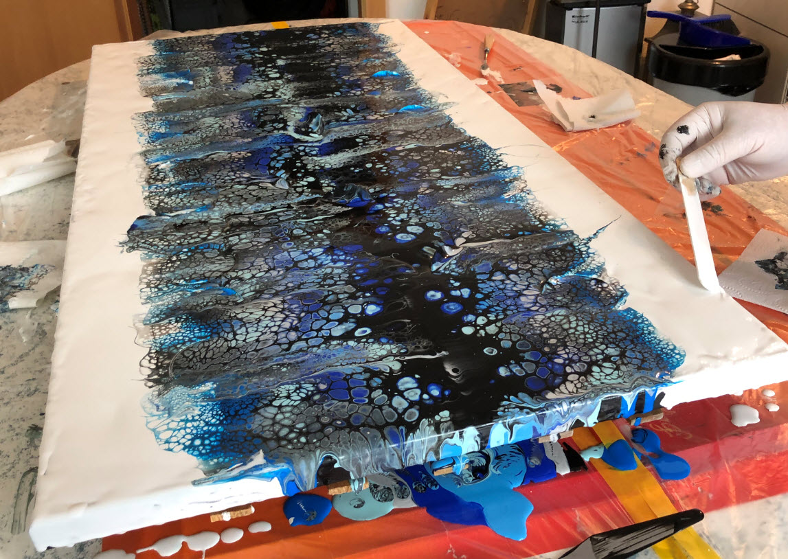
Black Canvas Detail
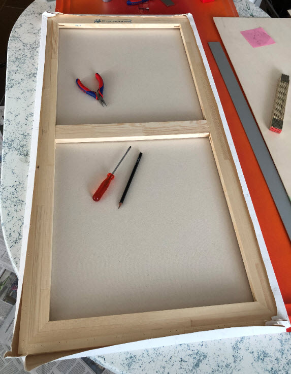
After 2-3 day drying, the canvas gets removed from the frame and prepared for cutting:
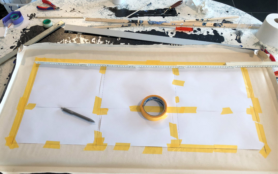
Marking for Laser Cut
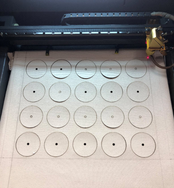
Because of the limits of the laser cutter, the canvas had to be cut in three steps: top, middle and bottom:
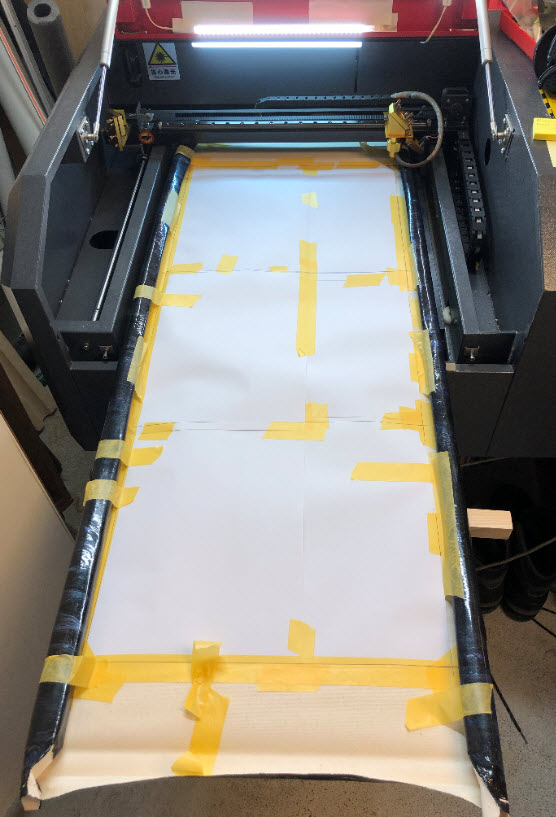
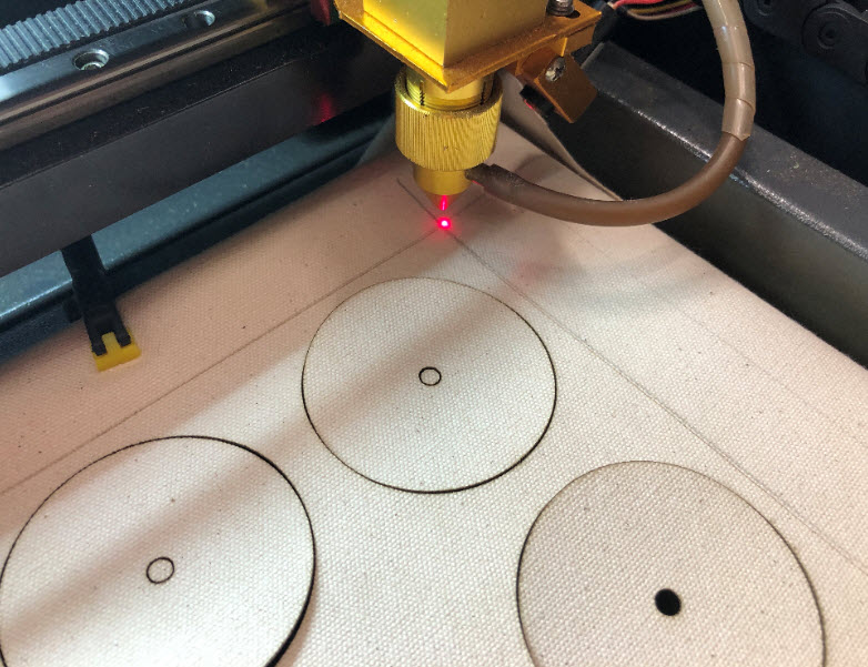
Canvas in laser cutter
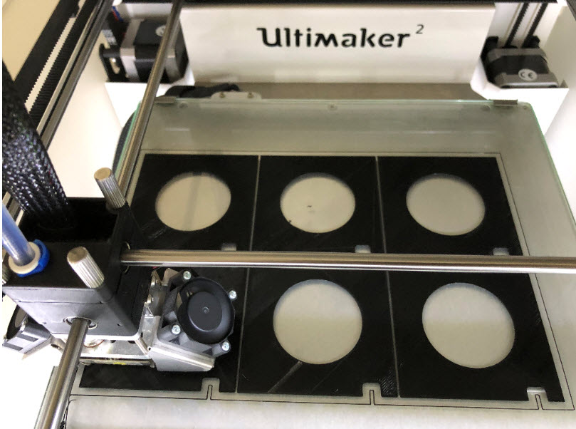
Cutting first third
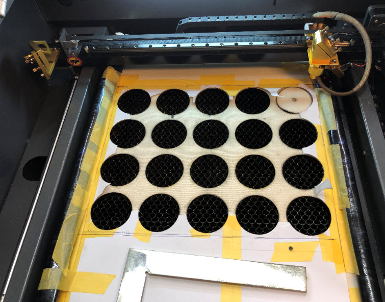
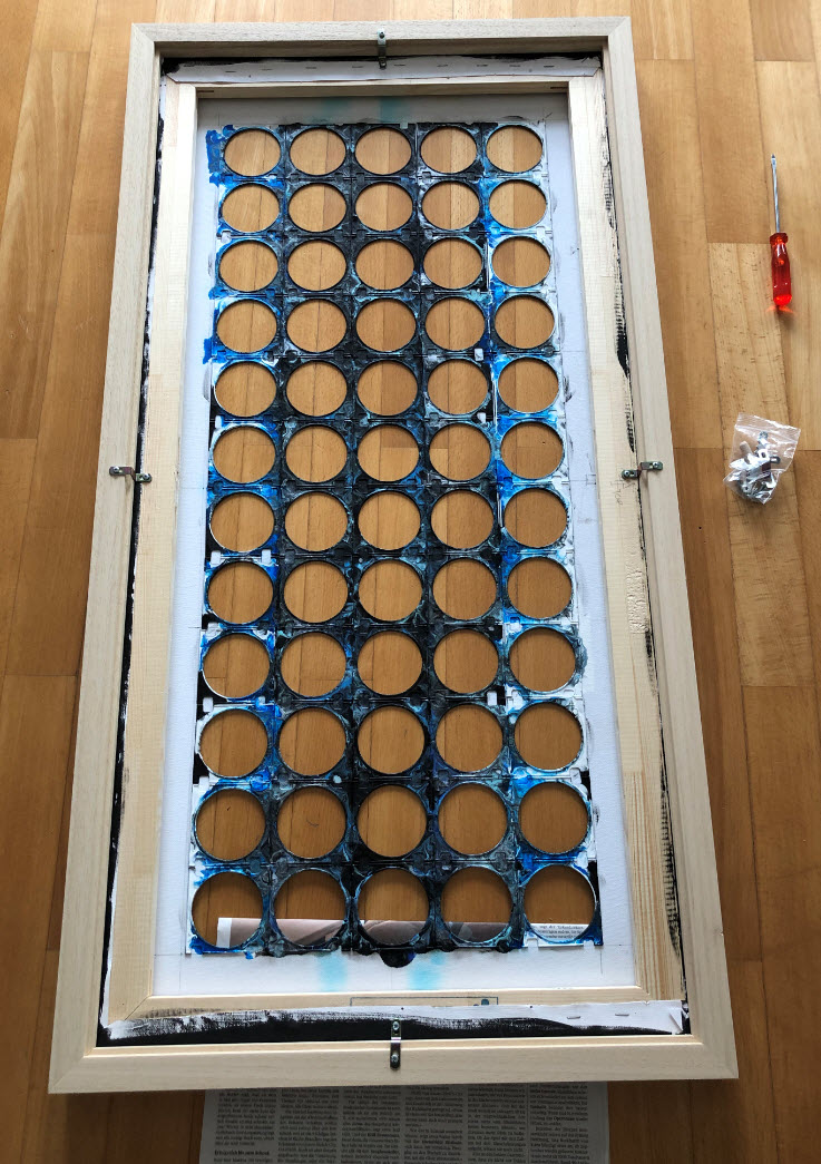
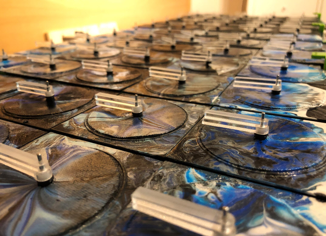
The round cut-outs get placed between motors and LED rings:
Canvas round cutouts on motors
Because the canvas tends to warp and to cover the back, the round cutouts get glued on 3D printed holder:
Canvas Cutout Holder
Canvas Holder on Motors
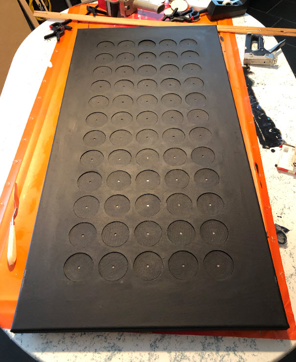
Black background
To make a tight fit with the boards and to prevent canvas warping on the cover canvas, similar 3D printed parts get added on the back of the canvas too:
3D Printing canvas holder

Backside of Canvas
Around the canvas a wooden frame gets added:

Canvas Frame

Blue ring color test
The second approach is to cut first, then paint. That makes it easier to cut the canvas:
Removing Canvas from the Frame
Cutting Canvas
Aligning the cutting steps:
Cutting Marker
Then glue the backside holders to the canvas:
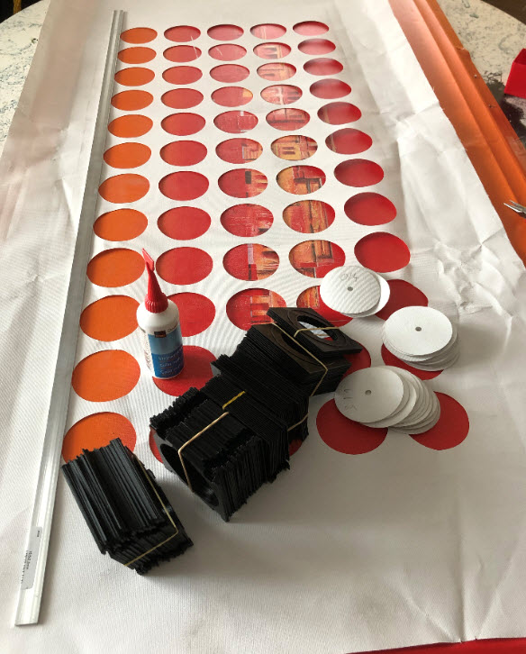
prepare for gluing
back side with holder
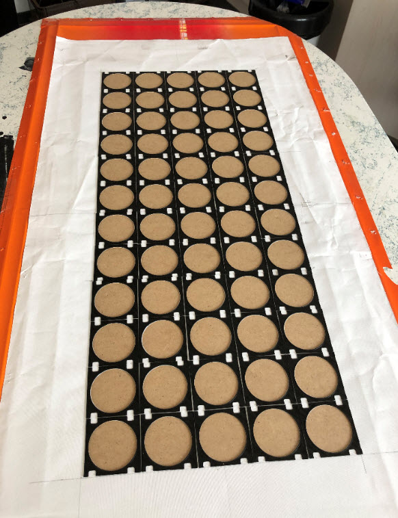
finished back side
Then attach it to the frame:
canvas attached to frame
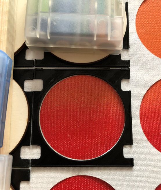
Glue the round cutouts to the holder:

glueing cutouts
Paint canvas and cutouts with Gesso.

Gesso on round cutouts
Then attach the cutouts back to the canvas:
Cutouts inserted

Back Fixture
The canvas of 50×100 cm needs about 1.5 liter of mixed acrylic paint:
Acrylic Colors Mixed
This time it is a ‘center swipe’ with white outside:

adding colors
Finish black color line
Doing a center swipe with a plastic sheet:
center swipe

more center swipes
small fixes

Color Detail
The glued cutout canvas was warping a bit because I did not use waterproof glue (next time I know better).

Cutout detail
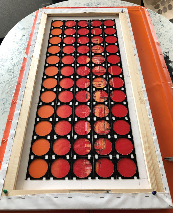
After about two hours, while the paint is still fluid, lift the canvas:

lifted canvas
canvas with cutouts
That way the paint for the cutouts can spread a bit on the lower holders:
cutouts
That way the areas outside of round canvas get enough acrylic paint:

fluid colors on round cutouts
Let it dry for about a week.
I feel the canvas looks better with an extra frame around it:
Added wooden frame

Frame on the wall
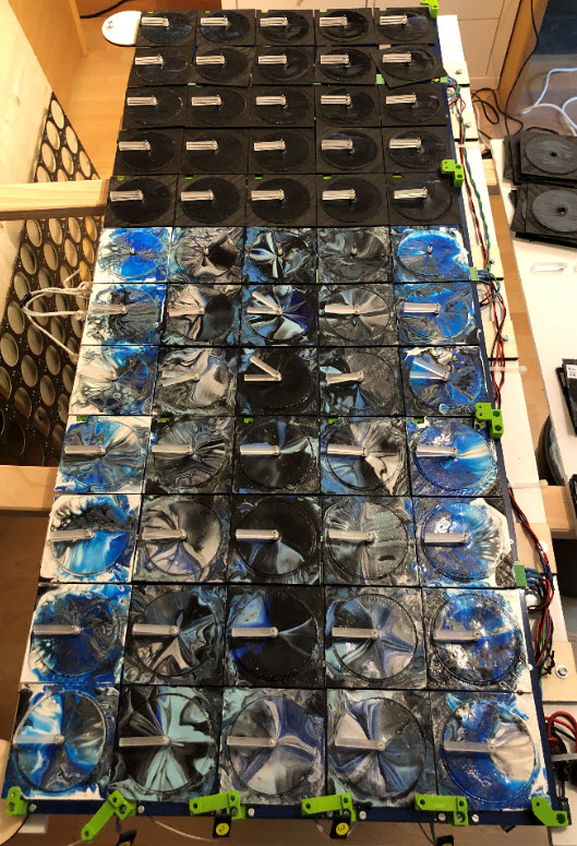
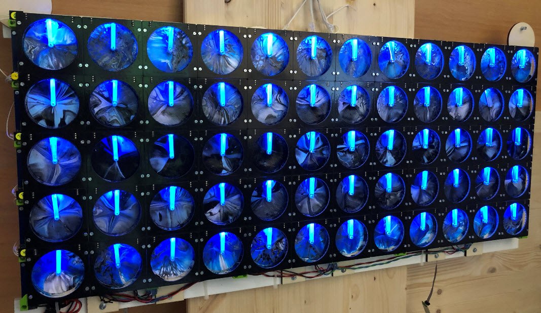
The concept allows combining different ‘skins’ with different ‘background’: here the second front canvas with the first back version:
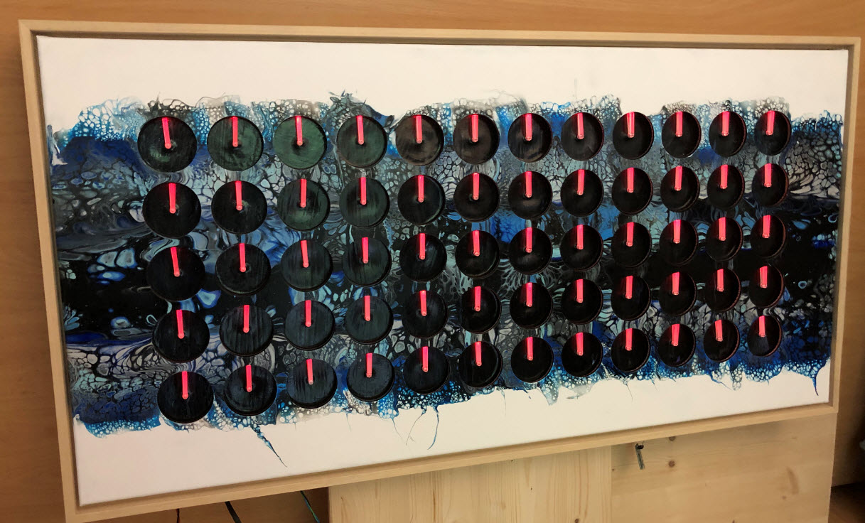
2nd Canvas with black background
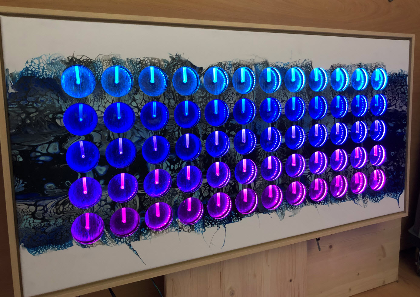
LED rings turned on
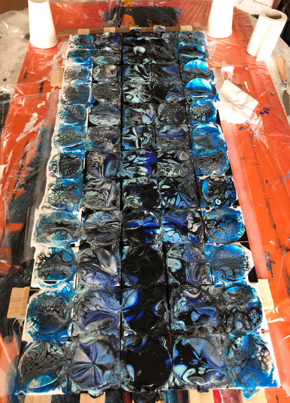
The front skin can be replaced in a few seconds. To replace the back skin I need around 30 minutes. The most difficult part is to have the puzzle pieces in the right place.

Back tiles
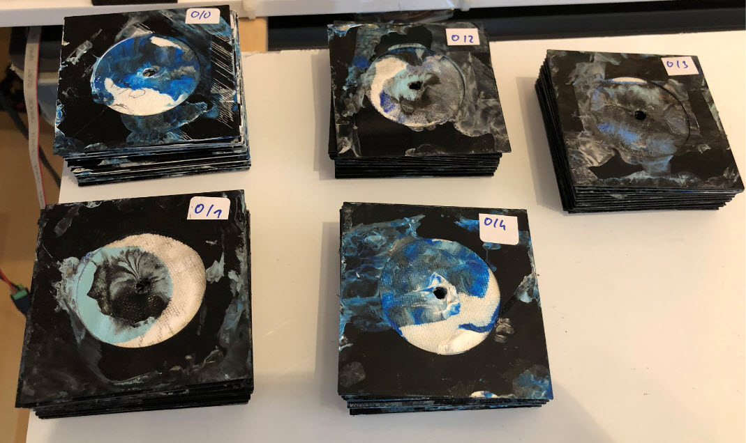
Markers on Back Tiles
Replacing Tiles
Tile Detail
Added LED Boards
LED Test
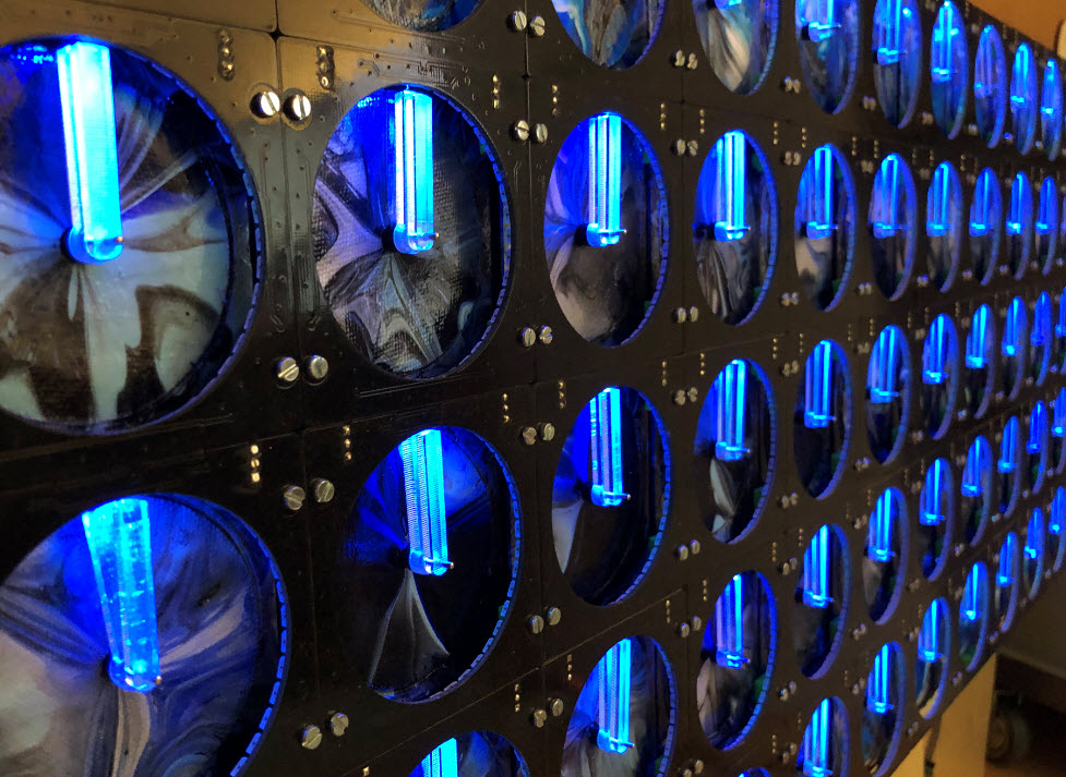
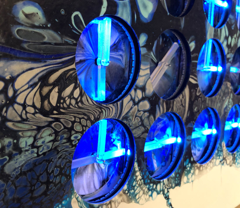
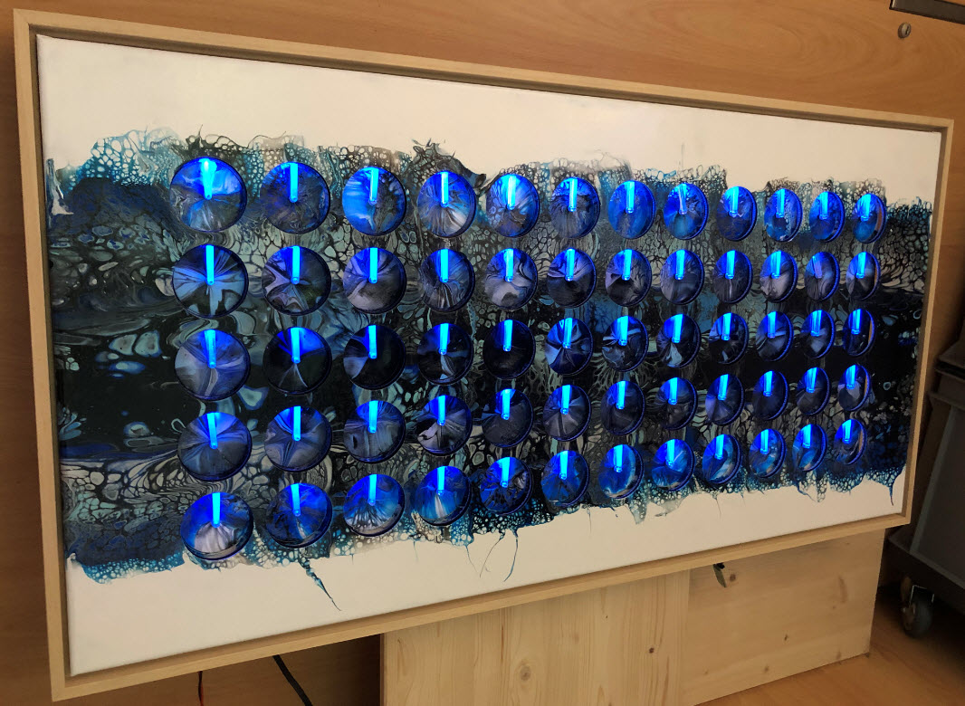
Blue
Blue Led Test
Added Frame
Summary
As always: there is room for improvements. The wiring and assembly of the build was time consuming, so I’m in the process to simplify things and make it more modular too. The firmware is still evolving, for example the ESP32/Wi-Fi support is still in the early stages, but works otherwise very well. Using the RS-485 as connection between the boards have been a good idea so far, but still want to improve the communication protocol and make it more parallel. The wish list grows, but there is still time to make the perfect next Christmas gift :-).
I hope this article is helpful and can be used as a base for your own endeavors in the electronics space and beyond. And don’t miss the links below to all the other information.
Happy Making 🙂
Links
- “60 Billion Lights”: 2400 RGB LEDs and 120 Stepper Motors hiding behind Canvas Art
- Files on GitHub: World Stepper Clock with NXP LPC845
- McuOnEclipse Library: https://github.com/ErichStyger/McuOnEclipseLibrary
- LPC845-BRK: Unboxing the NXP LPC845-BRK Board
- IDE and SDK: NXP MCUXpresso IDE V11
- SparkFun RS-485-to-USB converter: https://www.sparkfun.com/products/9822
- Project on GitHub: https://github.com/ErichStyger/mcuoneclipse/tree/master/Examples/MCUXpresso/LPC845-BRK/LPC845-WorldClock
- SparkFun RS485 Breakout: https://www.sparkfun.com/products/10124
- SparkFun RS485 Converter: https://www.sparkfun.com/products/9822
- Adafruit BLE SPI Friend
- Adafruit Ambient Light Sensor (TSL2561)
- Adafruit TSL2591 Light Sensor

Very nice Erich, Thanks!
LikeLiked by 1 person
Pingback: New Version | MCU on Eclipse
When it comes to this kind of kinetic art, I feel like we’re following parallel paths, but you’re always three steps ahead of me. The first time I saw such an installation was in San Francisco in a lobby that displayed “A Million Times 120”. I was fascinated and wanted to build my own. Of course, I found the original 3×8, but that was too expensive and not enough of a challenge. Then I found various posts that you also list. Lastly, I found your post that since, you had to take down. That one was by far the most informative. I chose a different path (Arduino Due, I2C, X40 motors, etc.), but bit by bit I was getting there. Then I thought of adding four RGB LEDs per clock at 3, 6, 9 and 12, but then I backed down and used only one at 12. Separately, I was also discovering acrylic pouring. I tried a few paintings, so I thought of also combing the clock with the acrylic pouring, but soon after I decided that it would have been too much. So, in the end, I finished the project with a 3×8 matrix of clocks and 24 RGB LEDs, one per clock. And then I saw this page! The result is simply amazing! It’s just incredible how you managed to bring all these three elements together in such a cohesive manner. I look forward to one day being able to see your work in a museum or even being able to afford to buy one. Oh, one last similarity. As I was building this, my wife left me alone. She figured I’ll find a new project and lose interest. Once I was done with it however, the question came: “So, where are you going to put this?” Luckily I had some space in the office. 🙂
LikeLike
Hi Dragos,
wow, this is really huge: our souls must be connected :-).
In case you missed it: I have been working on a new hardware design (https://mcuoneclipse.com/2020/07/19/new-version/) which makes building and installing it much easier. I’m in the finish phase of building another 60 clock version with it, again with an acrylic pouring canvas, but having LED rings above the canvas. A bit of a different approach with the same concept, but making a different effect.
As for kinetic art: there is yet another project underway (still not sure if it will work out): using moving acrylic ‘pixels’ with RGB LED illumination. Will see how this one goes … 🙂
Erich
LikeLike
Yes, I do feel a kinship with you. 🙂
The modular clock system is awesome! Your students are so lucky!
For the “pixel” art, let’s see if we’re still on the same page. What I was thinking is having a matrix of wood pegs. Behind them there is an X-Y gantry. The gantry brings a plunger behind each peg and pushes it out based on that pixel’s “intensity”. At the end, you have formed a picture. To clear it, you pull all the pegs back in. Am I close? 🙂
Lastly, not that you don’t have enough ideas, I built a 5×5 replica of this:
https://artcom.de/en/project/kinetic-rain/
https://artcom.de/en/project/dancing-particles/
Dragos
LikeLike
Hi Dragos,
about the pixels: each pixel has a motor attached on the bottom. The pegs are made of acrylic, and they are illuminated with RGB LEDs from the bottom. Together they form a picture or can ‘draw’ numbers/letters.
Thanks for sharing the thing with the ‘rain drops’: I saw that idea in a different installation (but not sure where), but that’s definitely something cool. And it looks for sure cool with many of these drops :-).
LikeLike
Pingback: New MetaClockClock V3 finished with 60 Clocks | MCU on Eclipse
Pingback: MetaClockClock Build Instructions | MCU on Eclipse
Pingback: Flip-Dot Clock using Used Bus Parts | MCU on Eclipse