
I always have been fascinated by electromechanical stuff like these Flip-Dot Displays.

I received my flip-dot 20×16 module as a donation by surprise from the UK (thanks James!). It seems that they are especially available in the UK (search on ebay for ‘hanover flip dot’). There are different kind of modules, in different sizes, from different vendors. Mine is a is from ‘Hanover’ which actually uses 7-dot modules from BROSE.

See “Fun with Flip-Dot Displays” for how they work.
Hardware
What you need:
- One of the ‘Hanover’ display modules. I have a ‘rear bus sign’ with 20×14 dots
- A 24V DC power supply (1A should be fine)
- RTC with backup battery, e.g. DS3232
- RS-485 transceiver, e.g. Sparkfun breakout board
- Microcontroller board, e.g. NXP LPC845-BRK or FRDM-K22F
You can easily use a breadboard with breakout modules. See this article how to make it based on the LPC845-BRK.

Below is the image of the back side of the module with the controller board:

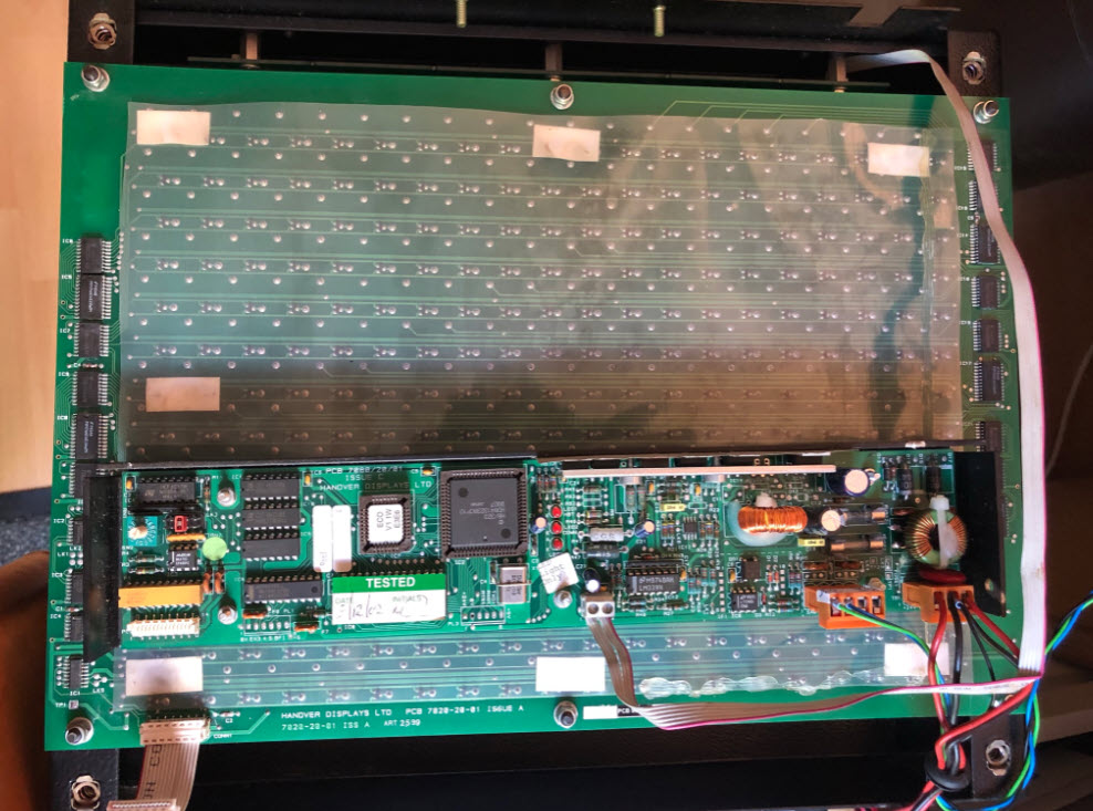
The module comes with a driver hardware using an old Hitachi H8/500 (I wrote my first compiler and toolchain for that device 🙂 ).

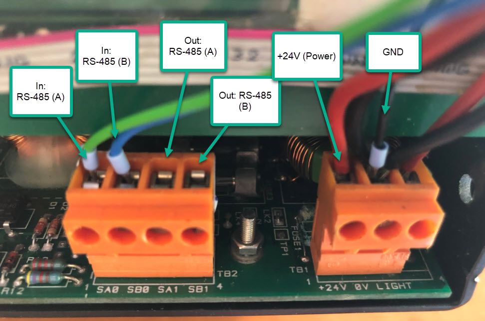
Connect Power and communication to the orange connectors. RS-485 is using 4800 baud using a special ‘Hex-ASCII’ protocol including a checksum.
There is a rotary switch which is used to set the device board address (there can be multiple displays in a bus): mine has the address set to 0x1. Note that you need to specify that address in the software.

You can see that red jumper which is set to the middle by default. Setting it to the ‘E’ position will run an internal test sequence.
As all what the display needs is power plus RS-485, I decided to use my existing hardware I have created for the MetaClockClock:

It is run by an ARM Cortex-M4F (NXP K22FN512) and includes battery backup for RTC, a BLE wireless module plus the needed RS-485 transceiver.
Software
It took me a while to implement the protocol (framing, data format, checksum), and for this the implementation by hawkz was a gib help.
The project is using Eclipse (MCUXpresso IDE) with the NXP MCUXpresso SDK and runs with FreeRTOS.

Below the most relevant software parts:

The driver implements functions to set or clear dots or to write text.
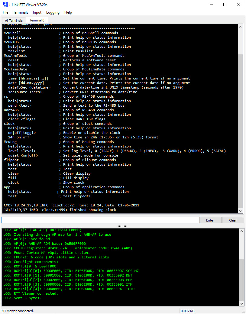
The project implements a console interface over BLE, UART and RTT:
You can find the full project on GiHub.
Summary
Flip-Dot displays are fascinating. Brand-new displays are hard to get and expensive. In case you get a chance to get one of the salvaged parts, I hope you find this article useful.
Happy flipping 🙂
Links
- Project of this article on GiHub.
- Overview about different hardware: https://radow.org/flip-dot-en.php
- Protocol reverse engineered (Python): https://github.com/hawkz/Hanover_Flipdot
- LPC845-BRK for RS-485: https://mcuoneclipse.com/2020/06/07/behind-the-canvas-making-of-60-billion-lights/

fascinating stuff. In the mid 80’s I worked with a company that made a special type of industrial flip display. It used bright, non-lit, fluorescent segments which were pushed onto or pulled from a glass pane. The segments were however submerged in an opaque, coloured liquid. The segment would disperse the liquid when up against the glass and become visible, when pulled it was invisible because it was replaced by the opaque liquid. A solenoid was used to do the flip. It only had to power it for a few milliseconds. surface tension from the liquid kept the segment against the glass.
It was very fast and clever for its day, but suffered from reliability issues. The solenoids also had huge current draws when flipping many segments at once and that made for big and failure prone power supplies. With todays technology it could probably be made to work better though.
LikeLiked by 1 person
Interesting approach with that liquid! Reminds me how many e-paper displays work (https://mcuoneclipse.com/2017/11/04/fascinating-details-of-waveshare-e-paper-displays/): they are using small particles in a liquid which are pushed up or down in that fluid.
And electromagnets can draw a lot of power. That display I have needs around 100 mA if idle and around 300 mA if flipping the dots. What I did not get working is the LED back-light, not sure why.
LikeLike
Nice project – I used to see these modules in surplus stores around Toronto but they always were missing a few pieces.
Question, why didn’t you include a USB (CDC device would be easiest) in your list of interfaces?
LikeLiked by 1 person
Yes, it is a nice and rather quick and clean project thanks to the module and its enclosure.
USB CDC: I missed to list that one. Actually it has two USB-CDC: one through the K20 debug chip on board and one natively with the K22.
LikeLiked by 1 person