
Many applications need to store persistent (non-volatile) data at runtime: configuration data, error logs, sensor data, calibration values, etc. The question is: where to store that data? If it is only a few kBytes, an SD card or similar is an overkill. Adding an external EEPROM? Sure, that works, but adds an extra part to the design. Some microcontroller have internal EEPROM. But what if not? Why not using the microprocessor internal flash memory?

Internal FLASH vs. external EEPROM
Internal FLASH or external EEPROM?
Modern microcontroller have plenty of FLASH memory (128 kByte and more), and typically not everything is used. So instead adding an extra external EEPROM device to the design, I can consider to use the internal microcontroller FLASH program memory.
Points to consider using the internal FLASH:
- The FLASH memory is typically organized in pages (1 KByte, 2 KByte, 4 KByte, etc). Usually the full page needs to be erased first before being programmed. This takes both time and energy, which is critical if I want to do this while the microcontroller is shutting down because of a power loss.
- Many FLASH programming algorithms need the microcontroller interrupt switched off, so increases the interrupt latency time.
- The internal FLASH memory erase-program cycles are typically lower than the one for EEPROM. The internal FLASH typically has 10k-100k cycles, while external EEPROM can have 500k-1M cycles.
Typically I’m using the internal FLASH memory when there are only a few write cycles (e.g. ideal for product configuration data which is written only once), and only for smaller amount of data (few KBytes) in order not to impact the interrupt latency time. If I need to write large amount of data, or I’m concerned about erase-write cycles, then I typically use an external EEPROM, see “Driver for Microchip 24xx Serial EEPROM“.
There are devices which have internal EEPROM too: these devices are an alternative to external EEPROM, and typically have the same advantages and disadvantages.
What do I need?
In order to use the internal program memory for my data at runtime, I need
- Reserve/allocate a chunk of memory so it does not get used by the Linker for the constant data/program at runtime
- A library/function with the FLASH programming algorithm implemented I can use from my application.
Programming the internal FLASH with Processor Expert Component
Using Processor Expert makes things really easy, so I’m showing here the steps how I can program the FLASH with it. In my example I’m using the Freescale FRDM-KL25Z board, but steps and settings are very similar for any other architecture supported by Processor Expert.
IntFLASH Component
I add the IntFLASH (Internal FLASH) component to my project. It offers many functions to program the flash memory:

IntFLASH Processor Expert Component
There are functions to write a 8bit (SetByteFlash()), 16bit (SetWordFLASH()) or 32bit (SetLongFlash()) values. I prefer to use the SetBlockFlash() as with it I can write any size of data. These functions make the ‘flash programming applets’ which are needed to correctly erase and program the FLASH memory.
The component properties offers settings to configure how the programming shall be handled. Typically I use these settings:

IntFlash Settings
- Safe write (with save & erase) write method: the component will make a backup of the FLASH page before erasing the page. This needs a buffer of the size of the FLASH page. I have the buffer type implemented by the method. Alternatively I could provide a buffer from the application memory.
- Interrupts service/event disabled: I’m ok to use polled mode to wait for the programming finished.
- Wait in RAM: on many processors, the program FLASH memory bus is not accessible while the FLASH is programmed. With this setting the code waiting for the programming completed will run in RAM.
There are other settings explained in the help of the component (see “Getting Help on Processor Expert Components“).
An important information is provided by the code generated by the IntFLASH component: how big a flash page or sector is on my microcontroller. This is a define in the generated header file:
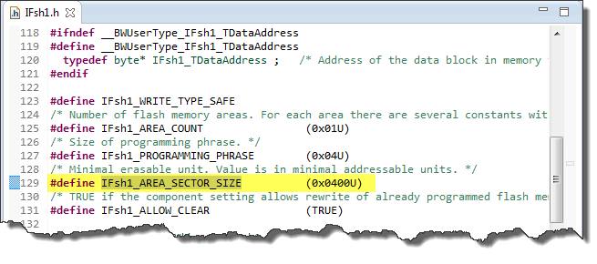
AREA_SECTOR_SIZE with the flash block size
So for my above example, it means that a flash block is 1 KByte (0x400). So an erase operation will erase that full block, and that when I allocate my data blocks below, it has to be aligned on that boundary and size.
Reserving Memory for my Data
I need to tell the linker that I’m going to use part of the FLASH memory for my data storage. Otherwise the linker might place data or program code in the area where I want to store my non-volatile data. Traditionally I change the linker file and reserve a section of memory so it is not used by the linker at link time.
For Processor Expert, I do this in the ‘Build options’ tab of the CPU component where I find the ROM/RAM areas generated in the linker file:
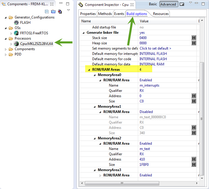
Build Options Tab of CPU component
For my KL25Z microcontroller, the FLASH memory (MemoryArea2) starts from 0x410 and has a size of 0x1FBF0:

Default KL25Z 128KByte FLASH Area
From above, I know that the FLASH block size is 0x400 (1 KByte), and I do not need more than one page, so I reduce the m_text size by 0x400 (0x1FBF0 ==> 0x1F7F0) and a new memory area with size 0x400 starting at address 0x1FC00:
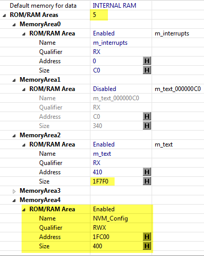
Added NVM_Config Section
Programming the FLASH from the Application
The last part is to use it from the application. Typically I have a header file like the one below where I have the addresses defined:
/**
 * \file
 * \brief Interface for the Non-Volatile-Memory
 * \author Erich Styger
 *
 * This provides an interface to store and retrieve data from the on-chip memory.
 */

#ifndef CONFIGNVM_H_
#define CONFIGNVM_H_

#define NVMC_FLASH_START_ADDR    0x1FC00 /* NVRM_Config, start address of configuration data in flash */
#define NVMC_FLASH_ERASED_UINT8  0xFF
#define NVMC_FLASH_ERASED_UINT16 0xFFFF

#define NVMC_REFLECTANCE_DATA_START_ADDR  (NVMC_FLASH_START_ADDR)
#define NVMC_REFLECTANCE_DATA_SIZE        (8*2*2) /* maximum of 8 sensors (min and max) values with 16 bits */
#define NVMC_REFLECTANCE_END_ADDR         (NVMC_REFLECTANCE_DATA_START_ADDR+NVMC_REFLECTANCE_DATA_SIZE)

#define NVMC_SUMO_DATA_START_ADDR         (NVMC_REFLECTANCE_END_ADDR)
#define NVMC_SUMO_DATA_SIZE               (4) /* 4 bytes of data */
#define NVMC_SUMO_END_ADDR                (NVMC_SUMO_DATA_START_ADDR+NVMC_SUMO_DATA_SIZE)

uint8_t NVMC_SaveReflectanceData(void *data, uint16_t dataSize);
void *NVMC_GetReflectanceData(void);

uint8_t NVMC_SaveSumoData(void *data, uint16_t dataSize);
void *NVMC_GetSumoData(void);

#endif /* CONFIGNVM_H_ */
In that header file I have the addresses defined (based on the start address), plus getter and setter routines.
❗ Be careful about alignment. E.g. on many devices the addresses have to be aligned to 4 bytes for 32bit accesses.
The implementation then looks like this:
/**
 * \file
 * \brief Implementation of Non-Volatile-Memory storage
 * \author Erich Styger
 *
 * This provides an implementation to store and retrieve data from the on-chip memory.
 */

#include "NVM_Config.h"
#include "IFsh1.h"

static bool isErased(uint8_t *ptr, int nofBytes) {
  while (nofBytes>0) {
    if (*ptr!=0xFF) {
      return FALSE; /* byte not erased */
    }
    ptr++;
    nofBytes--;
  }
  return TRUE;
}

uint8_t NVMC_SaveReflectanceData(void *data, uint16_t dataSize) {
  if (dataSize>NVMC_REFLECTANCE_DATA_SIZE) {
    return ERR_OVERFLOW;
  }
  return IFsh1_SetBlockFlash(data, (IFsh1_TAddress)(NVMC_REFLECTANCE_DATA_START_ADDR), dataSize);
}

void *NVMC_GetReflectanceData(void) {
  if (isErased((uint8_t*)NVMC_REFLECTANCE_DATA_START_ADDR, NVMC_REFLECTANCE_DATA_SIZE)) {
    return NULL;
  }
  return (void*)NVMC_REFLECTANCE_DATA_START_ADDR;
}

uint8_t NVMC_SaveSumoData(void *data, uint16_t dataSize) {
  if (dataSize>NVMC_SUMO_DATA_SIZE) {
    return ERR_OVERFLOW;
  }
  return IFsh1_SetBlockFlash(data, (IFsh1_TAddress)(NVMC_SUMO_DATA_START_ADDR), dataSize);
}

void *NVMC_GetSumoData(void) {
  if (isErased((uint8_t*)NVMC_SUMO_DATA_START_ADDR, NVMC_SUMO_DATA_SIZE)) {
    return NULL;
  }
  return (void*)NVMC_SUMO_DATA_START_ADDR;
}
There are many ways how this can be implemented, but the above way worked very well for me. The getter functions return NULL in case the FLASH has been erased which is the case if the debugger has programmed the application. That way I know if there is already configuration data present or not.
For example, in my Sumo robot I could have a sudden reset or power loss. When the robot restarts, I want it to read the last configuration data from FLASH. In this example I only need a bit (but can be used for other data too). I store the configuration data at runtime into FLASH with NVMC_SaveSumoData():
static void SUMO_ChangeRunSumo(bool runIt) {
  if (runIt != SUMO_doRunSumo) {
    /* value changed */
  #if PL_HAS_CONFIG_NVM
    uint16_t val;

    if (runIt) {
      val = 1; /* enable */
    } else {
      val = 0; /* disable */
    }
    (void)NVMC_SaveSumoData(&val, sizeof(val));
  #endif
    SUMO_doRunSumo = runIt;
  }
}
Then, if the robot starts, it checks the data in FLASH:
static portTASK_FUNCTION(SumoTask, pvParameters) {
#if PL_HAS_CONFIG_NVM
  void *p;
  uint16_t val;

  p = NVMC_GetSumoData();
  if (p!=NULL) {
    val = *(uint16_t*)p;
    if (val==1) {
      SUMO_doRunSumo = TRUE;
    } else {
      SUMO_doRunSumo = FALSE;
    }
  } else {
    SUMO_doRunSumo = FALSE;
  }
#endif
  (void)pvParameters; /* not used */
  SUMO_State = SUMO_STATE_IDLE; /* init state */
  for(;;) {
...
Summary
Instead of an external EEPROM, the microcontroller internal FLASH can be used to store and read data. With this, no external parts are needed, and usually there is plenty of room left on the microcontroller to store things like settings or calibration data. And with the use of Processor Expert it can be easily implemented. But the same principles apply for projects without Processor Expert: all what I need is a change in the linker script plus a FLASH programming library.
Happy Flashing 🙂

Thanks Erich! I needed that on my application.
LikeLike
Hi Erich,
A big THANKS for the support. This is very helpful.
I’m introducing the kinetis and codewarrior to my colleagues and students here in the Philippines. You’re blog is such a good reference.
LikeLike
I’ve been using this for years, and never failed so far. This method also brings data-security if the security options of the internal Flash is used. However, I find the PE a bit cumbersome to do this. I prefer doing in a more direct way, just including PageErase and ProgramByte functions, which could be obtained in Freescale’s application notes, and calling them.
LikeLike
Hi Erich,
I was wondering how can I implement writing a string in flash using this code. For example writing “mcu”, I want to every charter in each byte. And how am I supposed to read it back.
Thanks.
LikeLike
Writing a string is not any different than writing any other data.
To write such a string use e.g.
IFsh1_SetBlockFlash(“mcu”, (IFsh1_TAddress)(NVMC_STRING_START_ADDR), sizeof(“mcu”));
LikeLike
Hi Erich,
It returns this warning:
../Sources/NVM_Config.c:45:2: warning: pointer targets in passing argument 1 of ‘IFsh1_SetBlockFlash’ differ in signedness [-Wpointer-sign]
Also how can I read it back?
Thanks.
LikeLike
about the warning: simply insert a cast (I was too lazy).
There are multiple ways how to read the string. I recommend to use a getter function like shown in the post.
Or if you know that there is a valid string, you can use the pointer to the data (with a cast) too.
LikeLike
Thanks Erich.
Im very new to kinetis and some freescale mcu, so sorry for some newbie questions.
I will try our suggestions. I hope you have some discussion about this..
Regards…
LikeLike
Hi Erich,
In my case the JTAG programmer deletes the saved data when it reprogrames the MCU. What didn’t I configure? (I’ve followed every single details of your tutorial)
Thank you!
LikeLike
Yes, that’s intentional. The JTAG programmer performs a mass erase, and this will erase everything in the FLASH memory. Depending what you are using as programmer, you could configure it to not erase the data pages. See https://mcuoneclipse.com/2012/04/27/programming-part-of-flash/
LikeLike
Thank you very much, you are the best!!! 🙂
LikeLike
hello Erich,
what is the ‘platform.h’ file? where can i find it ? I use codewarrior 10.6. Thank you!
Best Regards .
LikeLike
Hi Alice,
it is a local file which I use to configure the platform/application behaviour.
An example of it you can find here: https://github.com/ErichStyger/mcuoneclipse/blob/master/Examples/MCUXpresso/FRDM-K22F/FRDM-K22F_FatFS_SD_Card/source/platform.h
But it is not relevant for this application/article, so I have removed it from this post.
Otherwise such a platform.h is what I use in most of my projects.
LikeLike
Erich ,Thank you !
I just started learning FLASH , can you Provide me a demo about erase and write flash simply without Processor Expert Component ? I want to learn the process at length. It is better about the kinetis and codewarrior 10.x .Thank you very much!
in detail
at length
LikeLike
Hi Alice,
I only have have use flash programming with Processor Expert drivers, because this simply works.
LikeLike
hi Erich,
I know kL25Z128vlk4 have 128k flash ,and the flash sector size is 1 k from datasheet, while where can i find the divide of sector or each sector’s addrees ?
LikeLike
Hi Alice,
you find the start of the flash area in the linker file. From that start address each sector boundary is at a 1k address boundary.
LikeLike
You find the memory map e.g. in the linker file:
MEMORY {
m_interrupts (RX) : ORIGIN = 0x00000000, LENGTH = 0x000000C0
m_text (RX) : ORIGIN = 0x00000410, LENGTH = 0x0001F7F0
m_data (RW) : ORIGIN = 0x1FFFF000, LENGTH = 0x00004000
NVM_Config (RWX) : ORIGIN = 0x0001FC00, LENGTH = 0x00000400
m_cfmprotrom (RX) : ORIGIN = 0x00000400, LENGTH = 0x00000010
}
LikeLike
Using PE is & a fixed address is abit ugly. Many times you don’t truly truly need to define the address manually. In CW you can force a variable to be in flash/rom if it is const & initialized & prefixed. You can then write to it without exceptions if it is sector aligned. For example: in global space write the following
__attribute__ ((aligned(0x400))) //Define in global space!
__inline const char myArray[0x400] = {};
then in your main you can write to it via the following:
IFsh1_SetByteFlash((uint32_t)(&myArray),’A’);
Note this “IFsh1_SetByteFlash” is the PE component demoed in the tutorial above. You could also write your own Flash driver if you want to eliminate the use of PE all together. See this tutorial combined with the information I just posted:
http://community.arm.com/groups/embedded/blog/2014/04/07/writing-data-to-flash-during-program-execution-with-the-freescale-kl25z-series
Sadly the “__attribute__ at” doesn’t work in CW. which is why you will need to do what I did above.
Anyhow, this method is nice cause it doesn’t force you to muck with the linker file.
LikeLike
Hi Nathan,
thanks for sharing! That’s indeed another nice way to do it, so I need to keep this one in mind. Using absolute addresses really is a brute force way to do it, I agree. About the __attribute__ syntax: did you use CW with GNU gcc, or with the Freescale ARM compiler?
LikeLike
Pingback: Unlocking and Erasing FLASH with Segger J-Link | MCU on Eclipse
Pingback: Tutorial: How to Erase the FLASH with the GNU debugger | MCU on Eclipse
Hello Mr Styger, best wishes for 2015! ( i know… im a bit late for that :S )
I amtrying to use the FlexNVM part of my K20DX72 which is supposed to have 32kb of Flex Memory. I think I’m a little confused but lets say I understand some parts of its functionnalities ( from AN4282 : Using the Kinetis Family Enhanced EEPROM Functionality ) :
– There is a EEE controller that uses the FlexRAM to backup in the FlexNVM depending on an EEPROM size.
– There is a splitting possible to treat the memory as part D-Flash and part E-Flash.
My question is, is the D-Flash part (A subsystem) the accessible part and the E-Flash (B subsystem) the automatic backup part not accessible because it is managed by the EEE controller? Or, is it that the 1kb “eeprom” size selected is mapped on the E-Flash (B subsystem) and the A subsystem is ordinary flash memory, that can be used at compile time as program code or data?
What confuses me is in the intFlash_LDD, I use 8kb for the EEPROM backup size, for a 512 bytes Eeprom size. For my cpu, Flex Memory starts at 0x10000000 and is 32kb large. Doing so, gives me 0x6000kb Dflash block (0x8000kb – 0x2000kb) that can be mapped in the “Build Options”of the Cpu component. I was guessing that the 8kb(->512bytes) I wanted to configure as eeprom was mapped after the Dflash and managed by the EEE controller. I wanted to use the IntFLASH component to access the eeprom data but somehow I can’t. My guess is, the FlexNVM can be splitted like so 1/8 (A) + 7/8 (B), A subsystem is the accessible part and B subsystem is the backup part, the ratio gives you endurance, and my EEPROM address is starting at 0x10000000.
I’m a bit confused because your example above doesn’t seem to use the FlexNVM, but ratter uses direct flash access without the EEE controller part and the FlexRAM. Or maybe it is, and the EEPROM is actually mapped on the Flash Block 1, I just don’t understand how everything works.
As usual, thanks for your help,
Mevon
LikeLike
From AN4282 : Using the Kinetis Family Enhanced EEPROM Functionality :
“How FlexMemory EEE works
To provide enhanced EEPROM functionality, the FlexMemory uses a RAM block (FlexRAM), a flash
block (FlexNVM), and EEE state machine. When the EEE functionality is enabled, the FlexRAM becomes
your EEE memory. The FlexRAM address space is where you access all of your EEE data. When the EEE
is accessed, the EEE state machine keeps track of the data and backs it up as data records, stored in some
portion of the FlexNVM used as an E-flash. Using a large block of E-flash to back up the data for a smaller
amount of EEE data allows the FlexMemory EEE implementation to offer extremely high endurance.
”
My guess is I need to access the FlexRAM to access the FlexNVM ( FlexRAM address range = 0x1400_0000 – 0x1400_07FF) and the “virtual eeprom” is not accessible from within the IntFLASH component?
Thanks immensly,
Mevon
LikeLike
Hi Mevon,
I have nearly no experience with the EEPROM/FlexNVM functionality, so I appologize that I’m not able to help you here 😦
Erich
LikeLike
Hi Erich,
Thanks for the post, it has been very useful.
About how to read the data from the flash, I understand the getting methods with: byte, word, or longe because the functions have as argument the pointer to return the data.
But I don’t understand how to use the SetBlock Flash, there’s not poiter. I looked in web and in the component help, but I still don’t get it. ¿Can you give me an example?
Thank you.
LikeLike
Hi Camilo,
SetBlockFlash() uses int32 (a 32bit number which corresponds to the memory address). Below is an example how I use it:
#define NVMC_REFLECTANCE_DATA_START_ADDR  (NVMC_FLASH_START_ADDR)

#define NVMC_REFLECTANCE_DATA_SIZE        (6*2*2) /* maximum of 6 sensors (min and max) values with 16 bits */

#define NVMC_REFLECTANCE_END_ADDR         (NVMC_REFLECTANCE_DATA_START_ADDR+NVMC_REFLECTANCE_DATA_SIZE)
uint8_t NVMC_SaveReflectanceData(void *data, uint16_t dataSize) {
if (dataSize>NVMC_REFLECTANCE_DATA_SIZE) {
return ERR_OVERFLOW;
}
return IFsh1_SetBlockFlash(data, (IFsh1_TAddress)(NVMC_REFLECTANCE_DATA_START_ADDR), dataSize);
}
...
if (NVMC_SaveReflectanceData((void*)&SensorCalibMinMax, sizeof(SensorCalibMinMax))!=ERR_OK) {
SHELL_SendString((unsigned char*)"FAILED saving calibration.\r\n");
}
...
LikeLike
Hi Eric, Thanks for the answer, I understand.
I’m having a problem saving the data, may be you know the solution.
This is the function that I’m using to save the data:
byte SaveFileCount (byte index, void* data, word dataSize) {
if (dataSize > FILE_COUNT_DATA_SIZE) {
return ERR_OVERFLOW;
}
return IFsh1_SetBlockFlash((IFsh1_TDataAddress)data, (IFsh1_TAddress)(FILE_COUNT_START_ADDR + index), dataSize);
}
This is how I’m using the function:
…
int count;
…
err = SaveFileCount(index,(void*)&count, sizeof(count));
if (err == ERR_OK){
(void)CDC1_SendString((str) “\r\nSaved!”);
} else {
(void)CDC1_SendString((str) “\r\nNot saved! “);
CDC_SendInteger(e);
}
…
With the serial port I change the value of count and try to save it.
The problem is that in the first try just after the debugger, works fine, but in a second try with a different value it fails except when the value is zero or sometimes when is 1 or 2. After that, works only when the value is the same that it’s already saved.
When fails Always the error is: ERR_VALUE – Read value is not equal to written value.
Do you know what is the problem?
Thank you so much.
LikeLike
Hi Camilo, have you configured the flash driver that it uses ‘safe write’ with erase?
LikeLike
No, I haven’t.
That was the problem, I’ve set the write mode to ‘safe write’ and now it works well.
Thank you so much for the help.
LikeLike
Hi erich,
I want to increase the endurance and hence i’m using 2 sectors for eeprom emulation. when the data storing is started in the next sector, i’m erasing the previous sector. For this, sector0 start = 1fc00 size 400, and what do i configure the next sector start address? How do i arrive at this value? i tried setting 20000 as the sector1 start address, throws an error “there is no access into the memory from 20000 to 20400” in cpu->build options->ram/rom. Please advise.
thanks,
pramod tm
LikeLike
I just realized this is 128k part and i’m trying to write beyond it which doesn’t exist. I have decreased the m_text by 0x400 and the new sector starts from 128k-0x800-(other rx/rwx). It works as expected.
Thanks,
Pramod TM
LikeLike
Hi Erich,
Thanks for the post, it has been very useful.
I’m working with the “FRDM-K64F” platform and I can not determine the start address of the “Flex Memory,” then I can not set the parameters for the memory space reserved. I put any direction, up from blocks allocated in the CPU, and tells me that does not exist direction. Something similar to the post of “March 15, 2015 at 14:32”.
But I have another problem before that. When I add the component IntFLASH, I set everything as you indicate you and to generate the code, it generates this:
….
#ifndef __BWUserType_IFsh1_TDataAddress
#define __BWUserType_IFsh1_TDataAddress
typedef byte* IFsh1_TDataAddress ; /* Address of the data block in memory for methods Get/SetBlockFlash. To maintain backward compatibility, it is double-word on Freescale 56800/E family, otherwise it is pointer to the smallest addressable unit (byte). */
#endif
#define IFsh1_WRITE_TYPE_SAFE
/* Number of flash memory areas. For each area there are several constants with information about the area. */
#define IFsh1_AREA_COUNT (0x02U)
/* TRUE if the component setting allows rewrite of already programmed flash memory location. */
#define IFsh1_ALLOW_CLEAR (TRUE)
typedef LDD_FLASH_TAddress IFsh1_TAddress;
….
and I can not set values:
/* Minimal erasable unit. Value is in minimal addressable units */
#define IFsh1_AREA_SECTOR_SIZE (0x0400U)
It will be for the component version, or the version of CodeWarrior, or the platform I’m using?
I hope you can help me, because I’m really stuck with it to save non-volatile values.
Thank you,
Gabriel
LikeLike
Hi Gabriel,
I have not used FlexMemory with the K64F, and it even could not be available on that device (I think it depends on the part number). As for the Flash sector size: this is device (flash technology specific).
LikeLike
Erich,
Another great post, thank you! My question is that I have a software version that I would like to store in the NVM section that I created. I would prefer not to write the version string to the flash at each boot as this is unnecessary wear on the device. Is there a way to put a variable in the flash at a specific memory location. I have tired the __attribute__((at(0x1FD60))); and I do not think that at() it is supported by GCC. I read your your post titled about defining variables at absolute addresses with GCC (https://mcuoneclipse.com/2012/11/01/defining-variables-at-absolute-addresses-with-gcc/) but the problem with this is that in my data is not at the start of the new memory area NVM_Config area, is this what the “aligned” modifier is for? Also it appears that you manually have to change the linker file for this, and that is not ideal for my application as this is an easily forgotten step that could “break” the application down the road.
I also need to add a CRC to my flash image so I read the SRecord article you wrote, I was thinking if all else fails I could concatenate a custom S19 file that contains the version string at the correct addresse(s), but that sounds FAR more complicated… I am hoping there is an easy way to force the 7 bytes in flash that I need. Thank you in advance for the help!!
LikeLike
Hi CoryF,
Not sure why you think it is necessary to write the version string to FLASH at each boot? You only need to do this if the version information is erased or really need to be updated. and yes, at() is not supported in GNU/gcc, and you already have found the right article how to place variables at a given address :-). Aligned is used to make sure the variable/object is properly aligned according to the bus/CPU architecture (e.g. that each 32bit variable is at a 4byte address. And I can definitely recommend the SRecord utility, as this one makes all these more complex things possible. Give it a try.
LikeLike
Hello Erich,
Thank you for yet another great posting. I am trying to implement a similar use of internal Flash for non-volatile data storage. I have discovered an issue that I believe may be a bug in processor expert. Perhaps you can weigh-in on our discussion in the Freescale forum: freescale community thread/357531
It would be helpful to know if I’m crazy, or just doing something I shouldn’t do…
🙂
LikeLike
Hello,
I only read that community post at a high level. I have to say that in all my cases I’m using the ‘safe write’ method, and not the ‘write’ only method. But from the description, I’m of the opinion that you have found a bug in Processor Expert flash programming?
LikeLike
Hi Erich,
Thanks again for this great tutorial !
I have a little and maybe dummy question about address and size of pointed data in the flash memory, probably linked with the alignment. I am a little confusing about that.
I understand that :
1FC00 : represents the starting address of the data user
400 : is the size of available space for that data
1FC00 + 1 : should be the second available address
1FC00 + 2 : should be the third available address
…
First question for be sure: 400 does it represent the number of available address ? Means that the last address is 1FC00 + 400 ?
After:
If I want to write a uint8_t (1 bytes, 8bits) : I can use one of this address, without constraint.
If I want to write a uint16_t (2 bytes, 16bits) : need to use an address that can be devised per 2 ?
If I want to write a uint32_t (4 bytes, 32bits) : need to use an address that can be devised per 4 ?
so, does it mean that each address point to a space of 8 bits ?
If yes, it’s will mean that 400 represents : 4*8^2=256 bytes, which is different from 1Kbytes
I probably have some mistake in my understanding, but cannot find where…
Thanks in advice for your answer 😉
LikeLike
Hi Romaric,
The 400 is 0x400 (hexadecimal) which is 4*0x100 which is 4*256 which is 1024 (1 KByte).
The 400 you see in the screenshot has a ‘H’ which means it is in hexadecimal.
I hope that makes now sense?
LikeLike
You right! It was the point!
Thank you 🙂
LikeLike
Hello Erich,
Thank you very much for this greate tutorial.
I have aproblem when I debug the code. i just want to write a byte in the Flash. When i try to write a byte with the method IFsh1_SetByteFlash(dest_addr, data), the compiler just jump to the __thump_startup() methode in the __arm_start.c file!! i do not understand why its happened?
Thanks in advice!
Hani
LikeLike
Hello Hani,
if the code jumps back to the startup code, it usually means your microcontroller has performed a reset. That could be because of the watchdog (is it turned on? If so, you have to serve it because the flash programming can take a while).
I hope this helps,
Erich
LikeLike
Hello Erich,
The Watchdog is disabled! The code is just going in an infinit loop in the IFsh1_SetFlash(…) methode. see code below:
byte IFsh1_SetFlash(IFsh1_TDataAddress Src, IFsh1_TAddress Dst, word Count)
{
LDD_TError Result;
if (IFsh1_CmdPending) {
return ERR_BUSY;
}
IFsh1_CurrentCommand = IFsh1_CMD_WRITE;
IFsh1_CmdPending = TRUE;
Result = IntFlashLdd1_Write(IntFlashLdd1_DevDataPtr, (LDD_TData *)Src, Dst, (LDD_FLASH_TDataSize)Count); /* Start reading from the flash memory */
if (Result == ERR_OK) {
do {
IntFlashLdd1_Main(IntFlashLdd1_DevDataPtr);
} while (IFsh1_CmdPending);
Result = IFsh1_CmdResult;
} else {
IFsh1_CmdPending = FALSE; /* Command parameter error */
if (Result == ERR_PARAM_ADDRESS) {
Result = ERR_RANGE;
}
}
return (byte)Result;
}
the variable IFsh1_CmdPending is always True! therefor the loop goes infinitly!
What about the clock freq. for the Flash? my Bus frequency is 24Mhz. I am using the KEAZN8 with 8KB Flash.
Thank you in advice.
Hani
LikeLike
Hi Hani,
I don’t have this device, so I cannot verify it. But IFsh1_CmdPending tells me that it started the flashing, but never completed it.
Can you increase the stack size (to be sure that there is no suble stack overflow)?
What I don’t understand is: earlier you said that the device resets and goes to the startup vector, but now you say it is hanging in this loop?
Erich
LikeLike
Hi Erich,
Yes you are right, i explained it wrong.
So the Problem still the same, programm jumps to the start up, cause it took alot of time in the while loop. i tryed to preserve the region that i used to not be erased when the controller starts, but no changes. What did you mean with the stack? did you mean the size of my Flash area?
Hani
LikeLike
Hi Hani,
I suspect that you still have your watchpoint enabled/turned on.
With the stack I mean that you reserve enough memory for the stack. This is usually something like this in the linker file:
__stack_size = 0x0600; /* required amount of stack */
LikeLike
Hi Erich,
I am not using the isErased()-Methode! Is this aproblem?
Thanks
LikeLike
Hi Hani,
no, should not be. I’m using this to check if my flash is erased (initially) or not, so know if I should store data from my application or not.
Erich
LikeLike
Hi Erich,
you are right, the Watchdog was enabeld.
but i still have the problem that the program hanging in the loop but not jumps to the startup method! but if i stopp running it i foud it hanging in the startup method. i am setting the FTMRE clk to 5MHz. and i incrreased the stack size but no effect.
LikeLike
Hi Erich,
i have good news :).
if i enabel the interrupt service for the FTMRE component, the write method works fine! but the read method not, it jumps to the default interrupt handler method!! but i do not want to work with interrupts! i just want to write one byte to the flash and read it.
Thanks.
Hani
LikeLike
Hi Erich,
It works now. Thank you very much for your support. You are doing a greate job.
Hani
LikeLike
Hi Hani,
and what was the final solution? To to use interrupts for the flash programming?
Thanks,
Erich
LikeLike
Hi Erich,
the solution was without interrupts. The problem was that i just tryed to read the Flash with the IFhs1_GetByte()-Method, not like yo did! But with your reading Method (Pointer Dereference) it works correctly!
Hani
LikeLike
Hi Hani,
that’s strange, and I don’t understand why. But indeed I have not used that access methods as I don’t need them.
Thanks for letting me and everyone else know what solved it!
Erich
LikeLike
Hi Erich,
I think it is because of the interrupt. If I have the read methode and the interrupts are enabeld, so i have to get the byte in the ISR! but i did not find the ISR for the read method.
But I have another problem: first, if i tried to write out side my reserved memors arrea it success!! Why? I told the linker about the area for my NVM. The flash has a page size of 512 Bytes, but i just need half of it, so that i just reserved 256 Bytes (0x100). i am using the setByteFlash()-Method, i want just to write 3-4 Bytes in the NVM. But the problem is, if i try to write with the method the Memory overwrites it is self, e.g.:
eeprom_WriteByte((IFsh1_TAddress)0x1F00, 0x41);
eeprom_WriteByte((IFsh1_TAddress)0x1F10, 0x42);
eeprom_WriteByte((IFsh1_TAddress)0x1F20, 0x43);
After the three writes the memory should have 0x41@0x1F00, 0x42@0x1F10 and 0x43@0x1F20. Some times it is like this, but some times the second write it is 0x46 or some thing else, or it overwrites the first write, the same is with the third write??? i do not understand.
do i missing any thing? I need this for my project, i do not know where the problem is.
thank you in advice.
Hani
LikeLike
Hi Hani,
no, I think you are not missing anything. This sounds like a bug to me. As for a try, can you add some delays between the writes to see if this helps? Otherwise I would recommend that you report this in the NXP forums so the engineeres could have a look at it.
Erich
LikeLike
Hello Erich,
I have already added a delay between the writes, but did not help!
Should the Flash Clock be divided to get it around 1 Mhz?
Hani
LikeLike
Hi Hani,
a delay say of 100 ms? I don’t think that lowering the flash clock will help, but you can try that too as we are in ‘desperate mode’ anyway.
LikeLike
Hi Erich,
What about read and write latencies? I measure for the write ca. 8ms, and for reading ca. 100us? Is that possible? I searched in the rederence manual for KEAZN8 but i did not find any thing about timing?
Hani
LikeLike
Hi Hani,
writing to FLASH is much, much slower than reading it. So 8 ms is maybe not very fast, but yes, could be realistic. I recommend that you read the specs (if there are any) about how much time is needed for writing.
Erich
LikeLike
Hi, Erich
Thanks, very usefull post.
There is a question:
When KDS 3.2 with KSDK 1.3 used, what’s need to use instead
#include “flash1.h” and
IFsh1_SetBlockFlash() ?
Are other corrections needed?
Thanks in advice,
Andrey
LikeLike
Hi Andrey,
SDK 1.3 uses a completely different driver model, and the components start with fsl_*. I have not used it, but I think you should use the fsl_flash component from the SDK 1.3. Be aware that the API/etc is different.
I hope this helps,
Erich
LikeLike
Thanks
LikeLike
Hi Erich,
I would like to use program flash as EEPROM for kinetis MK10D processor.
currently I was using FLASH_LDD component PE project . According to your tutorial , I need to use intFLASH component.
FLASH_LDD component and intFLASH component are similar ?. Can I use intFLASH component instead of FLASH_LDD component ? Please help.
BR,
Rohit K.
LikeLike
Hi Rohit,
the FLASH_LDD is a component with a different interface (see https://mcuoneclipse.com/2012/07/26/there-is-a-time-and-date-for-both-worlds/). The IntFlash is what I use and is much simpler to use. Internally it might use the FLASH_LDD too, so if you can, go with the IntFlash one.
LikeLike
Hi Erich,
Thanks for your reply. I would like to know that can I write data at PFLASH address by external mean like JLINK debugger for kinetis MK10D processor.. I am able to read data from PFLASH address by JLINK debugger but not able to write data to PFLASH by JLINK debugger. please help.
Best Regards,
Rohit Khele
LikeLike
Hi Rohit,
do you mean you cannot write the PFLASH with the GDB debugger and the Segger J-Link debug probe?
LikeLike
Erich, thanks for a very useful post.
Do you have any suggestions for elegant ways to keep track of many variables saved to flash ? In your example, you had two variables (reflectance data, and Sumo data), and defined three parameters for each (start address, size, end address). This gets a bit lengthy if you have 20-30 variables to save. Would storing them as fields in a struct be a better option ? Any other suggestions ?
LikeLike
Hi Geoff,
using individual variables and ranges are preferred for me if I have different versions of the firmware, where the not every version of the firmware needs all variables. That way I can easily turn things off. The other advantage is that I have less dependencies between the user of the storage, and the storage itself. But as you say, that gets complicated with many items.
In that case, a struct is the better solution.
What I’m using as well is storing parameters/settings on SD card (see https://mcuoneclipse.com/2014/04/26/frdm-with-arduino-ethernet-shield-r3-part-4-minini/). For this, I was thinking to have something similar in FLASH. Maybe a mini file system. But that only make sense for lots of variables/settings, because with the file system there is overhead.
LikeLike
Pingback: Flash-based Configuration Data Using The ld Linker – vilimblog
Hi Erich, great and very usefull post, as usual. Thanks!
I normally work on custom boards using the Segger J-Link Pro, but I need to use this params saving method in the Freedom KL25 using its own OpenSDA. How could I preserve FLASH regions when using OpenSDA on the freedom board?
Best regards, Victor
LikeLike
Hi Victor,
if you use the Segger OpenSDA firmware (https://mcuoneclipse.com/2013/05/16/freedom-board-with-segger-opensda-debug-firmware/), then it is like with a Segger J-Link Pro and you can use it like that.
LikeLike
Hi Erich,
Thanks a lot for pointing me to your blog post. The Segger firmware worked relatively well but I was not able to implement an easy way to preserve the flash region. The method described here (https://community.nxp.com/docs/DOC-102167) did not work for me either.
At the end I decided to roll it back to the OpenSDA firmware as I found another of your own blogs covering the way to preserve flash regions using advanced configuration settings available in the debugger connection edition window for the P&E debugger. The option was available in CodeWarrior 10.6 for OpenSDA too and it worked for me.
Best regards, Victor
LikeLike
Hi Erich,
Need a little help! I want to store a value in flash, I saw your post in this link https://community.nxp.com/thread/329796 and I declared const char test[]=”hello” in my my bareboard project of FRDM-kl25z128 in code warrier 10.7. But I got an address like this:0x20002FF0. You can see it is not a flash address, So please help me to store a value in flash if you have time. I am really stuck in this, forgive me if I said anything stupid I am not pro embedded system 🙂
LikeLike
Hello,
I quickly tried this in CW for MCU 10.7, and it places the array ‘test’ into FLASH memory as expected for me. Are you sure you are not using a RAM target?
LikeLike
Hi Erich,
There is a big problem that should be mentioned here: if the CPU is in HSRUN mode (like 120Mhz) you cannot program the flash. This is true for lots of different M4’s, including the K22 and the K64 as far as I know.
My project is running the K22 clock at 120Mhz (with a 16Mhz ext crystal), and these steps don’t work for me. The solution is to switch to a slower clock (80Mhz would be okay) when doing the flash erase and flash writes.
Do you have a project that uses PEX to switch clocks in operation, I assume using the CPU_SetClockConfiguration() function to switch between them?
Brynn
LikeLike
Hi Brynn,
thanks for posting that comment, and indeed I saw such a discussion in the forums, and I thought that this was the problem I saw around the serial bootloader on K64F.
From what I can tell, that HSRUN does not exist on the K64F, and somehow I have seen the flash programming problem with lower speed too on the K64F :-(.
About switching clock configuration: yes, that’s the function to use. I believe I have a project somewhere using it on GitHub, but did not check.
LikeLike
I just tried using the CPU_SetClockConfiguration to switch to an 80Mhz clock instead of my 120Mhz clock, and it killed my USB connection. (otherwise it looked like it worked)
Is there a way to suspend the USB briefly while I switch to 80Mhz and do some flash operations, then switch back to the 120Mhz and resume the USB?
Or I’ll have to terminate the USB connection and then launch another after the clock returns to normal. I am just running CDC on the USB for a debug terminal connection – which is actually updating a 50×140 ANSI terminal screen 20 times a second which is lots of data…
LikeLike
Hi Brynn,
yes, the USB block needs that 48 MHz to operarate, otherwise the connection will be lost. I have built in the Init() and Deinit() functions in the USB stack. I have not used them for that, but I know another use has sucessfully used it to shut down the USB communication and then start it gain.
Or you might find a clock configuration with some prescalers which still keep the 48 MHz to the USB, but not sure if this will be supported easily.
After all, it might be simpler to use an external I2C or SPI flash for your data?
Erich
LikeLike
Hi Erich,
To late to change the hardware… I think we can live with losing the USB debug terminal when writing the calibration values.
I am working to impliment the code, and found that at the beginning of the kinetis NVM component code they run a check to see if you are in clock_configuration_0, and if not, returns an ERR_SPEED error.
Of course they seem to assume that clock_configuration_0 will be the NVM compatable speed, and anything else is not. My code has clock_configuration_0 being the 120Mhz, and _1 being the 80Mhz, so now I get a ERR_SPEED after slowing my clock…
(AND before when I had just the one speed of 120Mhz I never got a ERR_SPEED which would have been apropriate)
So short of rewriting the NVM PEX component, I’ll have to make clock config 0 be 80Mhz, and clock config 1 be the 120Mhz.
We have lots of critical real-time control and floating point, so not running at 120Mhz is not an option.
Brynn
LikeLike
I would have to change the clock dividers that are set in the Init_USB_OTG section in my own code when I change the cpu clock, and it would have to not hiccup or barf at the change. Which seems unlikely I could make that change without some upset. Not a problem, as the USB is only going to be for developers or a service tech, and writes to flash will only affect that debug port.
I will have to play with clock configs to make the number _0 one slow enough for the flash to be happy and _1 to be my Highspeed mode.
Brynn
LikeLike
Hi Erich,
great tutorial, as you usually do.
My question is:
I am using a Freescale K60DN512 and MQX4.1 .I am not using PE.
I need to store some data on NVM memory. I followed the MQX example flash_demo.c and it works fine.
The problem is on the re-flash the program (for example for an update of FW) which erase also my previous data stored into NVM memory.
Is there a way to preserve my NVM data after a reload of FLASH memory or I have to find another way (extern EEPROM bye I2C/SPI bus for example)? Thanks all,
Stefano
LikeLike
Hi Stefano,
what debug connection are you using? The Segger J-Link only will erase sectors which are used by the programmer.
For the P&E connection, P&E has added a ‘preserve’ option last year, see https://mcuoneclipse.com/2015/04/16/updated-pe-gdb-server-for-eclipse-connectattach-and-advanced-flash-programming/
I hope this helps,
Erich
LikeLike
Hi Erich, thanks for your answer. I am using a board (not TWR serie) with K60DN512 where has been “flasshed” the Bootloader with a JTAG (programmer USB Multilink Universal). Usually I re-flash the program with tftpd32 SW via Ethernet and I debug with debug printf . Asap I will take a look on PE link to preserve portion of memory.
Thanks again,
stefano
LikeLike
Hi Erich. I’m slowly moving over from KDS to MCUXpresso. One change is that manual modifications to the linker script is discouraged, and they recommend using the IDE to configure memory usage etc. I’ve looked through the documentation but haven’t quite understood how I could use the MCUXpresso IDE to configure the flash for saving a configuration variable, as you did in this article. Any chance you could provide a blog post on this ?
LikeLike
I have disabled automatic linker file generation for at least one of my projects. I agree that generating the linker file automatically is a good thing for new users or if you don’t need anything special, but changing the linker file is needed for any advanced projects.
I see if I can come up with an article on that subject over the next week. Would that be ok?
Erich
LikeLike
Thanks Erich. I’ve done some more reading and looking around, and think manually editing the linker file is what I’ll need to do. Since I am porting a project from KDS where I had already edited the linker file, it shouldn’t be hard to do the same thing in MCUXpresso.
LikeLike
Hi Geoff,
I found have something which should help you with your data placement.
In MCUXpresso IDE, use the menu Help > Help Content and search for “Placement of specific code/data items” (Chapter 12. Memory Configuration and Linker Scripts).
I’m not fully through that, but it seems that this is the way to go.
Erich
LikeLike
Thanks Erich. I did have a read through that section of the help file, but it seemed to be mostly offering ways to relocate code and/or data into specific RAM or flash blocks. But after bit more searching I’ve come across the following LPC support page which provides some instructions on how to allocate a variable to a specific address (basically, divide up and rename an existing block and place a single variable into the new block). They give the example of allocating a variable into an address in RAM, but I can’t see why it wouldn’t work also with flash also.
“Placing data at an address” https://community.nxp.com/thread/389101
LikeLike
Hi Erich,
Great snippets on applications for the KL family! I am working on a KL26Z eval board using PE/CodeWarrior. I follow the steps listed above to use the internal FLASH but encounter ‘There is no access into memory from 0x410 to 0xf1c00’ when changing the size of m_text area basically not allowing me to partition the memory as above! Suggestions? Comment?
LikeLike
Hi Avdit,
I’m not sure what you are saying? Where is this message coming from? I recommend that you partition the memory at the end of the lash area (e.g. reserve a 4K block).
I hope this helps,
Erich
LikeLike
I found these interesting articles describing how using a table and only erasing (garbage collecting) when needed.
ESA article: Using Flash Memory in Embedded Applications
http://www.esacademy.com/en/library/technical-articles-and-documents/8051-programming/using-flash-memory-in-embedded-applications.html
ST app note: AN2594
Click to access en.CD00165693.pdf
I think this should greatly increase the write life of my part when frequently updating the values of a few variables.
Do you know of a library or example of implementing EEPROM emulation on a Kinetis KL05 or similar? (Just asking before I roll my own 😉
LikeLike
Hi Paul,
thanks for sharing the two articles! The first one is a more general/generic one, but the one from STM describes the principle very well. I have not used EEPROM emulation yet: for critical applications I have added an external EEPROM (more costs, but more reliable), and if using the internal FLASH the number of writes were not critical (less than one per day). As for a Kinetis implementation, I have found:
Click to access AN4903.pdf
https://community.nxp.com/docs/DOC-94593
http://cache.freescale.com/files/32bit/doc/app_note/AN4282.pdf (but KL does not have Flexmemory, at least not the ones I’m using).
Erich
LikeLike
A bit late to the game but my question relates to blocking/non-blocking resources.
If I do not have DMA enables, will writes to FLASH be code-blocking? Resource (FLASH) blocking?
LikeLike
that depends on the flash controller on the chip and of the driver. Most I have seen are running a small program in RAM because the FLASH memory is blocked during programming. The bigger issue is that interrupts need to be disabled too.
LikeLike
Hi Erich,
This was a good tutorial where I learnt partitioning internal flash memory area into an NVM and saving my variables in the event of a power loss. However, what I intend on doing is using the 256 bytes of internal eeprom that I have available in my s9kean32 kinetis part. Is there a processor expert component for this?
One of the ways to do this is to instruct the compiler while I declare my variables itself, to allocate memory for what I want saved in the internal eeprom area i.e. 0x1000_0000–0x1000_00FF as per the datasheet. On further digging on the compiler user manual- I stumbled across this.
”
The compiler defines its own sections to organize the data and executable code it
generates. You may also define your own sections directly in your program’s source code.
Use the __declspec directive to specify where to place a single definition in object code.
The following listing shows an example.
Listing: Using the __declspec directive to specify where to place definitions
Defining Sections in Source Code.
#pragma define_section data_type “.myData” abs32 RW
__declspec(data_type) int red;
__declspec(data_type) int sky;
”
Where can I find more info on this? Any thoughts on the approach is appreciated.
Thanks!
LikeLike
I don’t have any S9KEA, so I cannot really comment on what this device can or cannot do.
But if you have Processor Expert support for that device, using flash or eeprom is very, very simple and straightforward.
As for _declspec and placing variables, see
I hope this helps,
Erich
LikeLike
Yes it does have PE support and I would rather not change the linker ld file. The thing is I do not want to steal memory from the flash that I have when I have 256 bytes of internal eeprom available to use I have at most 50 bytes to store. I will check into the Intflash PE component meanwhile. Thank you.
LikeLike
Hi Erich,
I made the instructions of this post and all ran very well.
I would like to ask you how many times we can write the Internal flash? Are there a approx limit to erase and write the flash memory?
Thank you!!!! 🙂
LikeLike
Hi Carlos,
you would have to check the device data sheet for this. Typically it is in the range or 50k erase-programming cycles for each block/sector.
LikeLike
Thank you so much!!!
LikeLike
Hi Erich,
I’ve set the write mode “safe write (with save & erase), but it fail if i write the same flash address “twice”.
I think maybe because it didn’t erase the address before I write it,
How to configured the flash driver that it uses ‘safe write’ with erase?
LikeLike
Hi Roger,
the ‘safe write’ does an erase before it programs it. And it works very well for me. What is the fail/error code? On thing is that you need to make sure that the address you are using is matching the device block boundaries.
LikeLike
Hi Erich,
Yes, I find the reason that I fail to write the address twice, it’s because I didn’t allow Eclipse to update the resource file when I switch to the correct CPU package. So, I just do the same thing all over again, and click OK that Eclipse update the related source files for me when I switch the CPU package, then it works!!!
But there is another point that, I need to use the Component “TimerInterrupt” , and it will fail if I didn’t enable the “interrupt sevice/event” in the “IntFLASH”. Component.
So if I need the Component “TimerInterrupt”, then it must also enable the “interrupt sevice/event” in the “IntFLASH”.
LikeLike
Hi Roger,
the interrupt setting in the IntFlash component is about the feature that the component would raise an interrupt (to my understanding) when it is finished. I never have used in that way.
I have projects with the IntFlash component and the TimerInterrupt one working side-by-side, so not sure why you see an issue?
LikeLike
Hello,
I have a problem on my KE06 I can’t write on the flash as you indicated.
I have executed all the instructions described above but it does not write anything and when I read the area I only get values & FF.
Thank you.
LikeLike
I don’t think I have a KE06 around (have to check). But I saw on other devices that in order to program the FLASH you have to run the microcontroller at a reduced speed. What is your clock speed while programming it?
LikeLike
Hi Erich,
the clock speed is FTMRE=1.2 MHz with a bus clock 24 MHz.
Thank you.
LikeLike
I have found my board again :-). I have put a simple example project on Git: https://github.com/ErichStyger/mcuoneclipse/tree/master/Examples/KDS/FRDM-KE06Z/FRDM-KE06Z_FlashPrg
Note that I had to reduce the clock rate in the IntFLASH component from 24 to 12 MHz.
LikeLike
Hi Erich,
I’m working with KL16 microcontroller and I’m using a piece of its internal FLASH memory like an EEPROM to store some data. I have this problem: when I turn the device ON and turn it OFF rapidly, the flash memory (my EEPROM) sometimes is erase. Do you have any idea aboute the problem cause?
Many thanks in advance for your support.
Kinds Regards,
Stefano
LikeLike
I have not observerd something like this. Does this happen (on-off) while you are programming it? then I would not be surprised. But after you have programmed it, this should not happen.
LikeLike
Hi Erich,
I removed from my firmware all the code pieces where it programms the FLASH, but the result doesn’t change. The stange thing is that the software works corretly, but the EPROM data are cancelled (0xFFFF value).
I read the EPROM data using a microcontroller UART. Not all data are cancelled, some of them are correct.
LikeLike
Hi Stefano,
this is really strange. I would think that in your case there was enough energy to pull the bits to 1, but not enough left to program them down to 0.
But once they are programmed, they do not change, right?
LikeLike
Hi Erich,
Once I programmed the EEPROM, and I turn the device ON and OFF rapidaly, sometimes the EEPROM data is cancelled. Their value is 0xFF.
LikeLike
This is really new to me and concerning. I cannot explain it.
LikeLike
Pingback: DIY ‘Meta Clock’ with 24 Analog Clocks | MCU on Eclipse
Pingback: Behind the Canvas: Making of “60 Billion Lights” | MCU on Eclipse
I just spent way too long getting making flash work on a SKEAZ128 chip bare board setup–the symptom was resetting when trying to write or erase the flash. A debug breakpoint right after the flash command made it work–but without the breakpoint it would reset.
The problem turned out to be an overlap of my first saved to flash variable with the top of the stack. The stack starts at the last address in the m_data section and works downward. I had put an m_FlashMirror section after the m_data section, and liking nice round numbers had let the two sections overlap–which PE did not complain about but should have. m_FlashMirror is a ram section for all the variables which I want saved to Flash, so all I have to do is write that block at the end of the day if anything has been changed, not worrying about individual variables.
Eric-your blog has saved me so many times I decided to add to it. Thank You.
LikeLike
Hi Andrew,
thank you so much for your addition and extra information: I’m not using the SKEA parts, but still this not will be very helpful for the many others who are using the same device as yours.
Thank you again!
Erich
LikeLike
Pingback: Key-Value pairs in FLASH Memory: file-system-less minINI | MCU on Eclipse