
Many times I start with a project and tutorial, only to get interrupted for emergency tasks and assignments. For a long time I wanted to add GPS (Global Positioning System) functionality to one of my projects. While I started a few months ago on this, it took me until this week-end to finish the at least the first part: a SD card data logger with GPS :-): I calculate global positioning and time information, can use it in Google maps and store it on a SD card:

Adafruit GPS Data Logger Shield on a FRDM-KL25Z Board
Adafruit Ultimate GPS Module and Shield
This tutorial is about using the Adafruit Ultimate GPS Data Logger Shield with Eclipse and Processor Expert. I’m using the Freescale FRDM-KL25Z board, but in general any board or hardware can be used, as long I have 5V, GND and RX on the microcontroller.
Adafruit offers several GPS offerings:
- GPS only module (http://www.adafruit.com/products/746)
- Data logger shield (http://www.adafruit.com/products/1272) which includes micro SD card slot and prototyping area
- Wearable GPS module (http://www.adafruit.com/products/1059)
- The GPS receive module alone (http://www.adafruit.com/products/790)
I ordered the data logger shield version because of the SD card socket integrated :-). Both options come with a backup battery which keeps time/data in the GPS module. The module comes with an internal patch antenna which worked very well for me, even in-house. I recommend the external antenna for better tracking performance.
💡 If you order the external antenna (http://www.adafruit.com/products/960), do not forget to order the SMA-to-uFL cable (http://www.adafruit.com/products/851).
I highly recommend to read trough the Adafruit Tutorial: https://learn.adafruit.com/adafruit-ultimate-gps-logger-shield
Hardware Setup
The shield comes with headers and backup battery:

Adafruit GPS Shield Package
Board Details
The board has a 3.3V Level shifter as both the SD card and the GPS module are 3.3V. The board is powered by 5V, and generates the 3.3V with a RT9193 DC-DC converter.

Adafruit GPS Shield Details
There is a ‘Direct Serial Switch’ for the Tx/Rx lines of the GPS module to Digital I/O D0/D1 of the Arduino shield. That way the signals can be routed directly to the K20 OpenSDA chip and sent to the host PC (as a direct serial connection to the host PC). I have not used that option, but used the signals directly with the microcontroller.
Headers
Instead using the included headers, I decided to use ‘stacking headers’ so I can easily probe the signals, and stack the shields. ‘Stackable headers’ are provided by many sources, e.g. Pololu #1035.
💡 If using the shield in an environment with vibrations, consider using ‘precision socket’ headers, as these stackable headers are wire-wrap headers and might cause contact problems.
I recommend to use another shield to align the headers before starting soldering:

Shield with stackable headers
R5 10k Ohm Pull-Up to 5V
Although the shield works with 3.3V systems, there is a 10k Pull-up resistor (R5) which pulls-up the SD card chip select line to +5V (before the 3.3V level shifter to the SD card). See board schematics here.

R5 Pull-Up to 5V
Because I want to control that line with my 3.3V ARM core, I decided to remove R5:

Removing R5 with SMD Desoldering Iron
R5 Removed
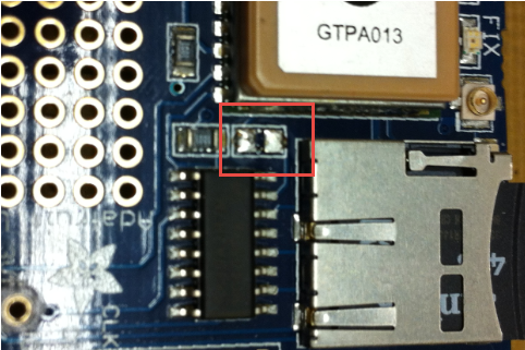
Mini-Signal Header
There is another mini-header which has all the important signals:
- 3V generated from the on board DC-DC converter
- CD (SD Card Detect)
- CCS: SD Chip Select
- PPS: GPS Pulse-Per-Second
- TX: serial from the GPS module to the microcontroller
- RX: serial from the microcontroller to the GPS module
I have added a header there too:

Mini Signal Header
Then insert the backup battery with the ‘+’ side up.
Minimal Connections for GPS Mode
To receive the GPS information, only three wires are needed: 5V, GND and GPS TX. It is easily possible to connect the shield ‘off-the-stack’ to a FRDM board like this:

Minimal GPS to Microcontroller Connections
That setup is ideal to get the pin assignments sorted out. Make sure the switch is on the ‘Soft Serial’ position:
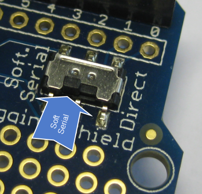
Soft Serial Position
For a new board, I recommend to prototype the connections in a first step:

Prototype Wiring
After that, I have wired the connections on the back like this:

Fixed Wiring (CORRECTION: Later I moved PPS to PTD4)
For the FRDM-KL25Z I have following connections to the microcontroller:
- SD MISO: PTD3
- SD MOSI: PTD2
- SD CLK: PTD1
- SD CS: PTD0
- SD CD: PTD5
- GPS Rx: PTE0
- GPS Tx: PTE1
- GPS PPS:
PTC8PTD4
This completes the hardware setup. Next step is to write the software :-).
Eclipse Project with Processor Expert
A complete project created with Eclipse (see “Constructing a Classroom IDE with Eclipse for ARM“) and Processor Expert is available on GitHub here. I do not go into the details of project creation. Instead I show the most important settings. The project includes already the settings for the SD card. See “Tutorial: Data Logger with the FRDM-K64F Board” how this works.
GPS PPS Signal: ExtInt (External Interrupt)
Once the GPS receiver has a lock, it produces a ‘PPS’ Pulse-per-Second every second for 100 ms:

GPS PPS Signal
I use an ExtInt (External Interrupt) Processor Expert component to trigger on the raising edge: That way I can either just count the pulses, or synchronize my internal clocks with it.

PPS External Interrupt Component
GPS Rx/TX: AsynchroSerial
I use the AsynchroSerial component to interface with the Rx/Tx lines of the GPS receiver. As the receiver is constantly sending data with 9600 baud by default, it is configured for that speed:

GPS Serial Component
Parsing the NMEA Messages
The GPS is constantly sending NMEA messages. To see them, you can use the command
nmea print msg on
For more details about NMEA sentences and what data they contain, check out this site
The most interesting message is the $GPRMC (RMC, Recommended Minimum Data) message:

NMEA GPS Messages
The message has the items separated by commas, and is terminated by \r\n:
$GPRMC,105056.000,A,4700.2752,N,00835.1145,E,0.33,106.84,310514,,,A*6D
means:
- $GPRMC: start of RMC message
- 105056.000: time (hh:mm:ss,ms) at GMT (Greenwich Mean Time) location. Your time zone offset needs to be added. I’m in GMT+1, so I need to add one hour.
- A (Active, have a lock), or V (void, no lock)
- 4700.2751, N: Latitude 47 degrees, 00.2751 decimal minutes North
- 00835.1145,E: Longitude 8 degrees, 35.1145 decimal minutes East
- 0.33: speed over ground in knots
- 106.84: track angle in degrees
- 310514: date (dd.mm.yy)
- ,,:The next two fields are always empty?
- A: seems to be the repeat of the Active or Void flag?
- *6D: checksum, everything between the ‘$’ and ‘*’
I have implemented a first version of the parser. See https://github.com/ErichStyger/mcuoneclipse/blob/master/Examples/Eclipse/FRDM-KL25Z/FRDM-KL25Z_Adafruit_GPS/Sources/NMEA.c.
The parser is in a FreeRTOS task: It indicates NMEA messages with LEDs, retrieves the message characters and stores them in a global buffer:
static portTASK_FUNCTION(NmeaTask, pvParameters) {
  GPS_TComData ch;

  (void)pvParameters; /* parameter not used */
  GPS_ClearRxBuf(); /* clear GPS RX buffer, as it already could contain some data */
  for(;;) {
    /* indicate we are receiving data from GPS with green and red LED */
    if (GPS_GetCharsInRxBuf()==0) {
      LEDR_Neg(); LEDG_Off(); /* blink red led if no GPS data */
    } else {
      LEDR_Off(); LEDG_Neg(); /* blink green led if we have GPS data */
    }
    while(GPS_GetCharsInRxBuf()!=0) { /* do we have data? */
      if (GPS_RecvChar(&ch)==ERR_OK) { /* yes, and no problem to get it */
        ReadChar(ch); /* read character and store in buffer */
        if (NMEA_printMsg) { /* print messages to console? */
          CLS1_SendChar(ch); /* yes, print it */
        } /* if */
      } /* if */
    } /* while */
    FRTOS1_vTaskDelay(200/portTICK_RATE_MS); /* give back some time */
  }
}
Once a valid message end (and start) is detected, it parses the message:
static void ReadChar(uint8_t ch) {
  static uint8_t prevCh = '\0'; /* needed to detect \r\n as end of a message */

  if (NMEA_parseMsg) { /* enabled to parse messages? */
    if (ch=='$') { /* check start of a message */
      NMEA_msgIdx = 0; /* reset index */
      prevCh = '\0'; /* reset previous char */
    }
    if (NMEA_msgIdx<sizeof(NMEA_msg)-1) { /* check for buffer overflow */
      NMEA_msg[NMEA_msgIdx++] = ch; /* store character */
    } else { /* message too long! */
      Err((uint8_t*)"Buffer overflow!");
      NMEA_msgIdx = 0;
      prevCh = '\0';
    }
    if (NMEA_msgIdx>sizeof("$GPxxx,") && (ch=='\n' && prevCh=='\r')) { /* valid end of message */
      NMEA_msg[NMEA_msgIdx] = '\0'; /* terminate */
      /* reached end of a message */
      if (UTIL1_strncmp((char*)NMEA_msg, (char*)"$GP", sizeof("$GP")-1)==0) { /* valid start of a message? */
        if (VerifyCheckSum(NMEA_msg)==ERR_OK) { /* check first the checksum */
          ParseMsg(); /* checksum ok, parse message and store data */
        } else {
          Err((uint8_t*)"Checksum failure!");
        }
      } else {
        Err((uint8_t*)"Message does not start with \"$GP\"?");
      }
    }
  }
  prevCh = ch;
}
With the shell I can check the status:
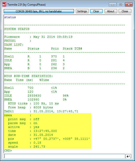
nmea status in shell
Location with Google Maps
The application already makes the correct coordinate transformation so I can copy-paste the position information into google maps:

Coordinates in Google Maps
Summary
With this GPS module I have a data logger with position information. I already have a special application in mind, let’s see how soon I can have it implemented :-). So I will constantly extend the project and sources on GitHub for it.
Happy GPSing 🙂

Pingback: Combining GPS Data Logger with Google Earth | MCU on Eclipse
Hi Erich,
I’m with difficult to download the source code of your project. I’m only getting download a folder with many others projects, except this. Can you send me this project by email ?
I bought this shield and i’m trying receive the messages on a arduino, for while. But i didnt get change the rate of the messages (from 1Hz to 0Hz or to 10Hz). I’m trying send the NMEA messages like this:
Serial1.write(“$PSRF103,02,00,00,01*20\r\n”);
but no one message has effect
Do you has some hint ?
LikeLike
Hi Thiago,
On https://github.com/ErichStyger/mcuoneclipse on the right hand side there is a button to download the full repository as a zip file: https://github.com/ErichStyger/mcuoneclipse/archive/master.zip
It seems to me that you are using ‘wiring’ code for Arduino: keep in mind that this repository is normal C code, not Arduino code.
And that I’m using Processor Expert with Eclipse, so you you cannot use the code for Arduino 1-to-1 as the way how to deal with the microcontroller is different.
LikeLike
Hi Erich, thanks for the reply.
I managed to download the project now, thanks for the link. I thought that i had downloaded the full repository before, but i hadn’t.
My other doubt was about the NMEA command to change the update rate of the messages. But today i found it here http://www.adafruit.com/datasheets/PMTK_A08.pdf
and everything its ok now 🙂
LikeLike
Pingback: Zumo Robot with WiFi and GPS | MCU on Eclipse
Hi Eric,
Great tutorial you have here, but there’s a bug with the parsing of coordinates that would discard the leading zeroes of the fractional minutes:
if (UTIL1_ScanDecimal16uNumber(&q, &coord->minutesfractional)!=ERR_OK) {
If the raw data was 123.0123, it would be printed out as 123.123 by the logging function:
UTIL1_strcatNum16u(buf, bufSize, coord.minutesfractional);
This could be alleviated using atof function from stdlib, but it does take up quite a lot of memory.
Another note for uBlox chipset users: the coordinates of uBlox 6 and above are in the format of 123.45678, so minutesfractional has to be a uint32_t.
Cheers!
LikeLike
Hi Roy,
many thanks for reporting that problem/bug!
I have now added a new function UTIL1_ScanDecimal32sDotNumber() to the Utility module (Git commit: https://github.com/ErichStyger/McuOnEclipse_PEx/commit/0df81f8290b423bfcee0bab637e7e854e4144595) and updated the implementation (Git commit: https://github.com/ErichStyger/mcuoneclipse/commit/69fb5cfa810ce2b2e5a96cf8a3863c0ca2a5ee73) using it. I had not a chance to test it with hardware, but I believe it should solve the problem you have reported. The updated Utility component will be part of the next *.PEupd release on SourceForge too.
LikeLike
Hi guys, i´m using this board with the Leonardo. Does someone have this code for the Leonardo? I´ll apprecciate your help.
Carlos Morera.
LikeLike
Hi Carlos,
No, I don’t have that for Leonoardo. But this project is with normal C/C++ code, and you can use that after replacing the low level layer with any microcontroller, including the Leonardo.
It just needs some porting, that’s it.
Erich
LikeLike