
The Freescale FRDM-K64F is a great board for data logger applications: it has a powerful ARM Cortex M4F with 120 MHz, 1 MB Flash and 256 KByte RAM. Best of all: it already has a micro SD card socket on the board :-).

Data Logger with FRDM-K64F
Outline
In “Arduino Data-Logger Shield with the FRDM-KL25Z Board” I already used the FRDM-KL25Z with the Arduino Data-Logger shield with CodeWarrior. Basically the same can be applied to the FRDM-K64F. I moved to Eclipse Kepler (see “Constructing a Classroom IDE with Eclipse for ARM“), so here is an updated tutorial: how to create a data logger application with the FRDM-K64F and Eclipse Kepler.
You need:
- Eclipse Kepler with Processor Expert as outlined in “Constructing a Classroom IDE with Eclipse for ARM“
- Freescale FRDM-K64F board with USB cable
- A micro SD card
💡 This tutorial can be used with CodeWarrior for MCU10.x, Processor Expert Driver Suite or Kinetis Design Studio too. The principle is the same, but the project creation steps will be somewhat different.
Make sure you have loaded the latest Processor Expert components from GitHub (see “Processor Expert Component *.PEupd Files on GitHub“).
The project created in this tutorial is available on GitHub: https://github.com/ErichStyger/mcuoneclipse/tree/master/Examples/Eclipse/FRDM-K64F/FRDM-K64F120M/FRDM-K64F_DataLogger.
In principle, this tutorial can be applied to any other board: Just make sure you select the microcontroller on your board, and adopt the pin settings for the devices you have.
While it would make sense to use an RTOS like FreeRTOS for a data logger, I’m showing here a ‘bare metal’ data logger. An RTOS with tasks then can be easily added to the project.
Creating the Project
❗ The steps below are for standard DIY Eclipse Kepler IDE and GNU ARM Eclipse. If you are using Kinetis Design Studio (KDS), then use the File > New > Kinetis Design Studio menu. If using CodeWarrior for MCU10.6, then use the File > New > Bareboard project. Note that the wizard pages are different. Create a Processor Expert project for the MK64FN1M0xxx12.
Use the menu File > New > C Project to create a new project:
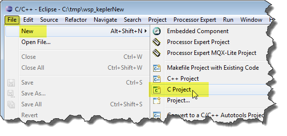
New Project
Provide a name for the Cross ARM GCC Freescale Processor Expert C/C++ Project:

DataLogger Cross ARM GCC Project for Processor Expert
Then select the M4 core with the PEx Driver Suite 10.4 Wizard invocation:

M4 core for PEx DriverSuite 10.4
In the next dialog I usually deselect the ‘Release’ configuration:
💡 In the Embedded World typically there is no such thing like ‘Release’ or ‘Debug’: it is always ‘Debug’, see “Debug vs. Release?“
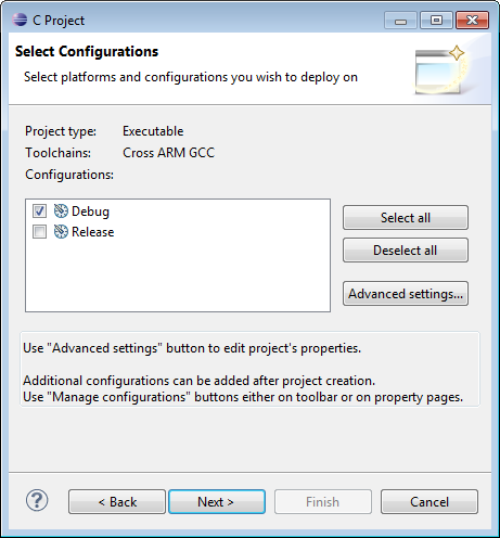
Debug only
In the next dialog I have the opportunity to configure the tool chain.
💡 I’m using the ${gcc_path} Eclipse variable to point to my GNU ARM Embedded tool chain (see “Constructing a Classroom IDE with Eclipse for ARM“)
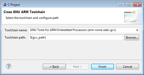
Cross GNU ARM Toolchain
Press ‘Finish’, and the project wizard calls the Processor Expert wizard to configure the microcontroller. Select the MK64FN1M0xxx12 which is present on the FRDM-K64F board:
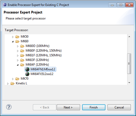
MK64FN1M0xxx12
In the next dialog I use ‘Linked’: this means that the project uses links to the Processor Expert library files. Alternatively you can use ‘Standalone’, then the files get copied into the project.

Linked Mode
Then I select the GNU C Compiler:

GNU C Compiler
With ‘Finish’ the project gets created. Processor Expert opens a help window explaining how to convert a project for Processor Expert. We can ignore this as the wizard already has done everything for us :-).
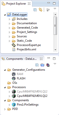
DataLogger Project
💡 I’m using Processor Expert views in the next step. If this is your first Processor Expert project, make sure select the menu Processor Expert > Show Views to open the needed views.
Project Cleanup and Adjustments
While the project created is fine, I usually do some cleanup. First I remove the ‘RAM’ configuration with the context menu, as I’m only going to use the FLASH target:
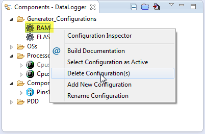
Deleting Configuration
Same for the obsolete CPU (orphaned now as it was tight to the RAM configuration):
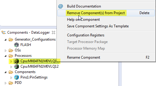
Removing RAM Configuration CPU
The MK64FN1M0VLQ12 derivative is a LQFP 144-pin package, but the FRDM-K64F board is using a LQFP 100-pin package. In the component inspector, I change it to the 100-pin package:
💡 Right click on CPU, select Inspector menu item to open the ‘Component Inspector’ view if not already open.

Changing CPU package
The PinSettings component can be removed, as we will care ourselves about the pin settings in the components:

PinSettings Component
Now the project is clean and using the 100-pin VLL12 package:
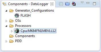
100-pin VLL12 package
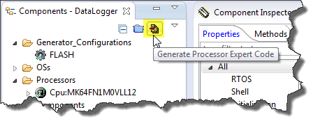
Generating Code
The project is still ’empty’, but at this stage I prefer to verify that I can generate code, build it and download it to the target. To generate the Processor Expert code I use the toolbar icon:

Generate Processor Expert Code
Building Project
To build the project I select the project and use the ‘Hammer’ drop down icon:

Building Project
It should build with no errors:
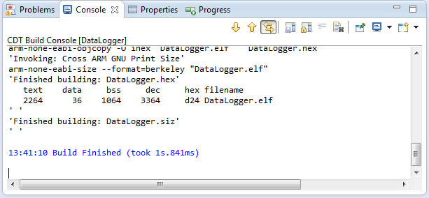
Console View with no Errors
Debugging
I’m using here the Segger OpenSDAv2 debug firmware on the FRDM-K64F board. I select the project and open the Debug Configurations:
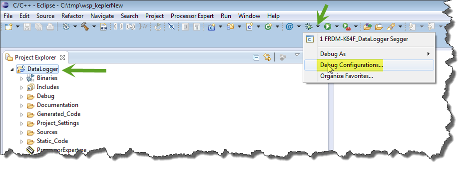
Menu Debug Configurations
The double-click on the GDB Segger J-Link Debugging item to create a new configuration: The .elf and project name should be filled automatically:

New Segger Launch Configuration
In the Debugger tab I make sure the proper device name (MK64FN1M0xxx12) and interface (SWD) is selected:
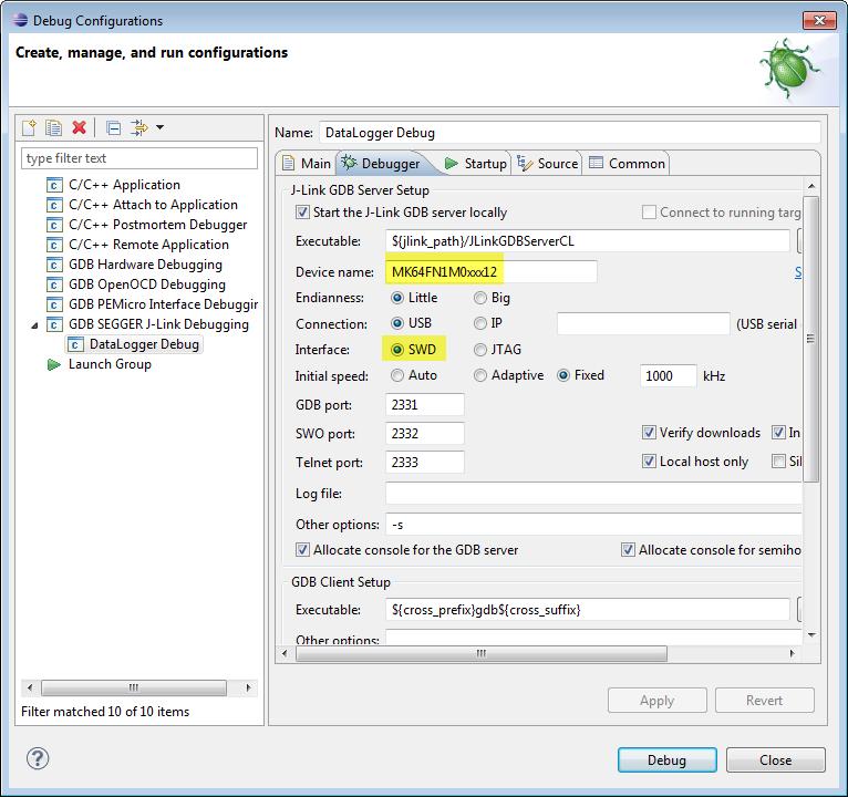
Device name and interface for Segger
In the Startup tab I make sure semihosting and SWO are disabled:
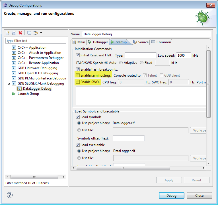
Segger Semihosting and SWO disabled
Pressing Apply (if any changes), then press Debug to launch the debugger, and I should be debugging:
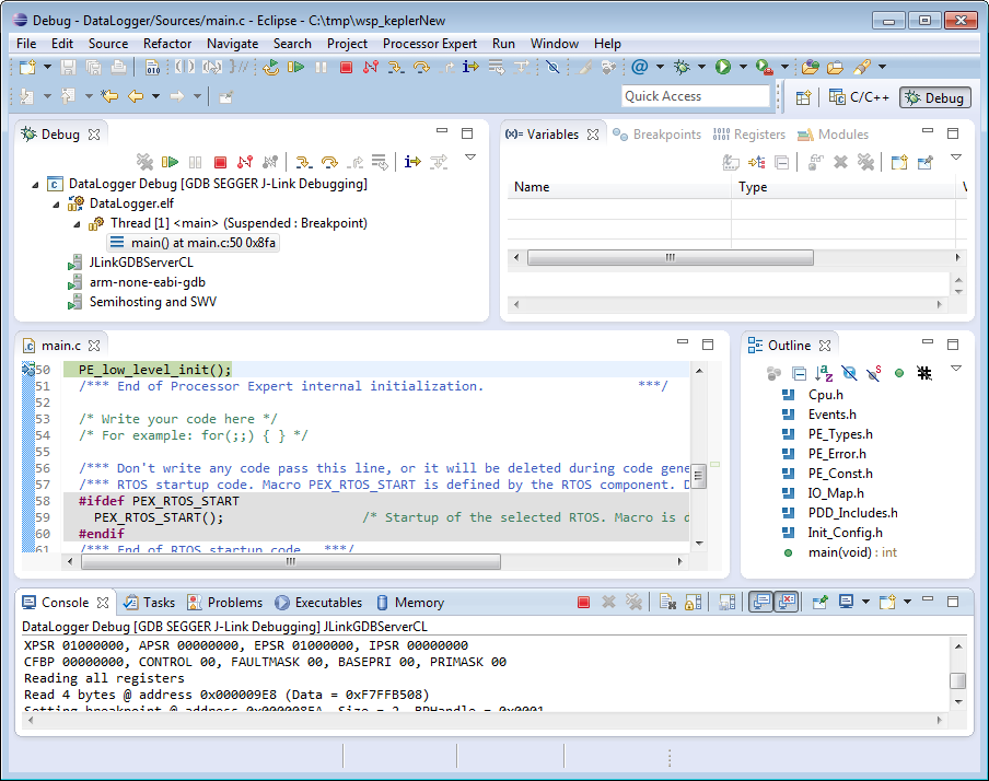
Initial Debug Session
So with this I know that everything works from building to debugging. Time to terminate the debugging session:
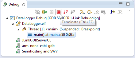
Terminating the debug session
And to return to the C/C++ perspective:
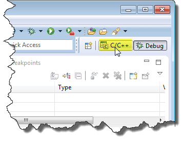
Return to C and C++ Perspective
FatFS File System
To use the SD card with the FAT file system, I add the FatFS component to the project:
As to write files to the file system I need date/time information, it asks me to add a clock component. I select the GenericTimeDate component:
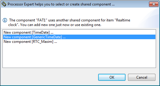
Adding GenericTimeDate Component
Next, FatFS needs a memory component, and here I select the SD_Card component:

Adding Memory Component for FatFS
To protect the critical sections, it asks me to select the component I want to use. It already should have added a Critical Section (CS1) component, so I go with the CS1 choice:

Linking to CS1 component
With this, I have new components added to my project. Some with a red X indicate that some settings are missing:

FatFS Components added
The latest version of the SD card component (extended after this article has been written): The LDD HW SPI uses the SPIMaster_LLD and the non-LDD HW SPI uses the SynchroMaster SPI implementation:
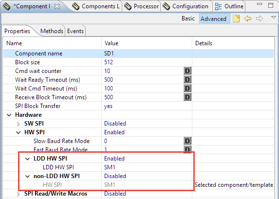
Different SPI components
💡 See “Switching between ‘tabs’ and ‘no-tabs’ UI in Processor Expert” to have the above table view.
One (and only one) SPI can be used, so you can enable one and disable the other(s). The steps are very similiar to the SPIMaster_LDD case below, and the SPI configuration should look something like this:
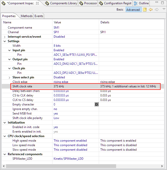
SynchroMaster Setting
Additionally make sure the following methods in yellow are turned on (has a checkmark on the icon, use the context menu to enable them):
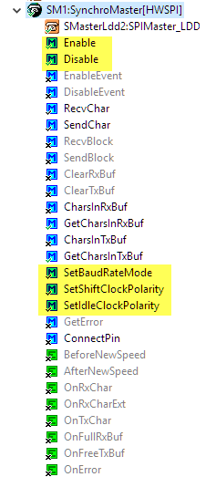
SPI SynchroMaster Methods
SPIMaster_LDD
In case for the SPIMaster_LDD, I need to configure the pins for the SPI which talks to the SD card. For this I open the Component inspector for the SPI component:

Need to configure the SPI
As the SD card on the board is connected to SPI1, I choose SPI1 as device with
- MISO/Input pin: PTE1
- MOSI/Output pin: PTE3
- SCLK/Clock pin: PTE2
- and no chip select list (use the ‘-‘ button to remove it)
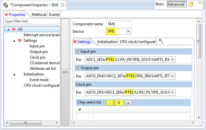
MISO, MOSI, Clock and chip select
The chip select list is not needed as the FatFs component will handle the chip select on its own. Scrolling down I need to configure the clock details. For this I clock on the ‘…’:
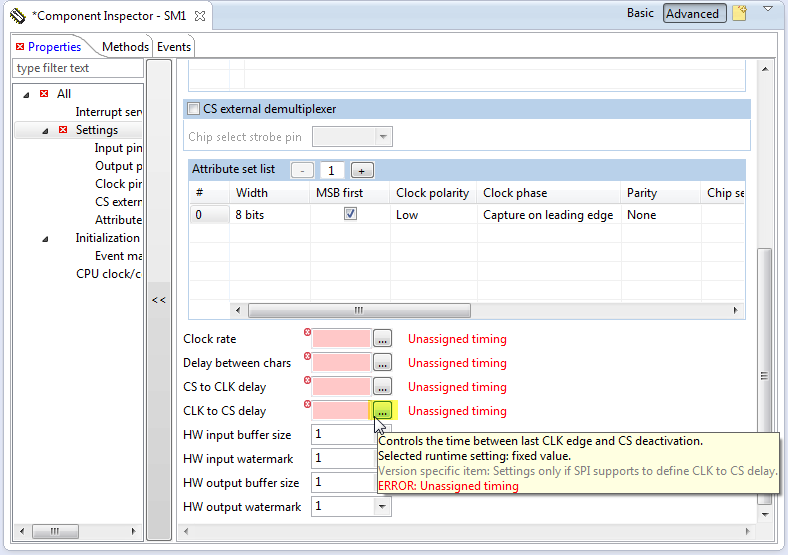
Configuring the clock
From the available timings, I double-click from the list on the right hand side to have a value assigned:

Selecting timing value
Then press OK, and do the same for the three delay timing needed:

Delay timing assigned
For the clock rate we not only need one timing, but three: initial/low and high-speed. Again clicking on the ‘…’ for the Clock rate to open the dialog.
I want to assign values in kHz, so I select that from the Unit drop down list (click into the Value field to have it updated):
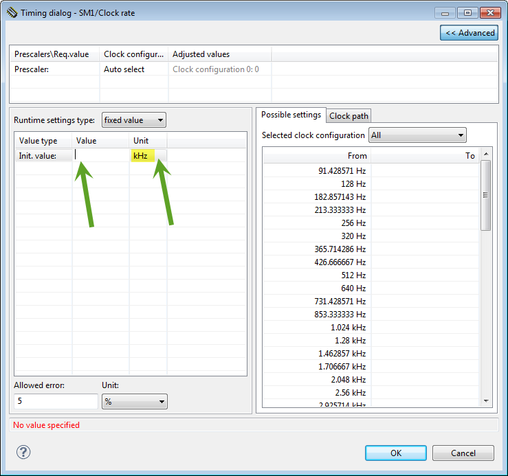
Clocks in kHz
As I need two values, I configure it as ‘List of values’:
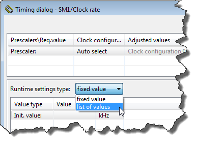
List of Values
Then I assign for the low value a maximum value of 375 kHz, and for high I can go up to 12 MHz (my clock configuration only allows 10 MHz max):
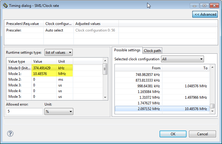
SPI Clock Values
Pressing OK to close the SPI clock configuration. To use the two configurations, I need to add a second attribute set. Because the ‘Tabs View’ uses a lot of screen real estate, it is easier if I switch to the ‘classic’ non-tabs view (small triangle in view toolbar to reach the menu):
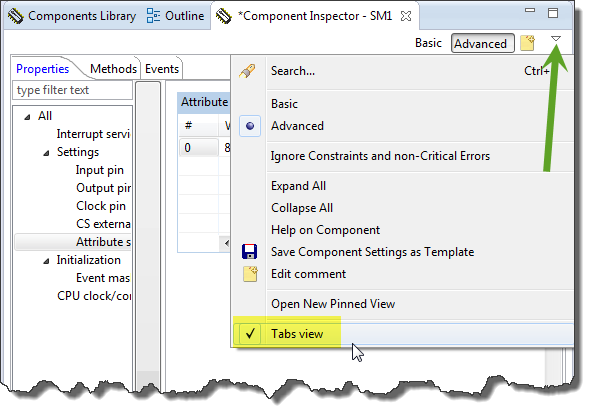
Disabling Tabs View
Next step is to enable the automatic initialization of the SPI component:
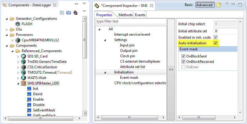
Automatic initialization of the SPI component
I click into the Attribute set list box (where the ‘1’ is) and click on the ‘+’:

Adding New Attribute Set
Then specify that the SPI clock index 1 shall be used:

Clock Rate Index for Attribute Set 1
The FatFS driver will change the SPI clock and configuration with the SM1_SelectConfiguration() method, so make sure you have it enabled in the SPIMaster_LDD: If the method icon has the ‘x’ on it, then it means it is disabled: enable it with the context menu:
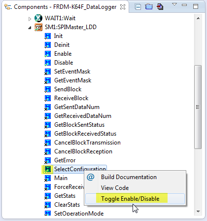
SelectConfiguration Enabled
In the SD_Card Component, I need to specify that it can use the index 1 (10 MHz) for fast mode:
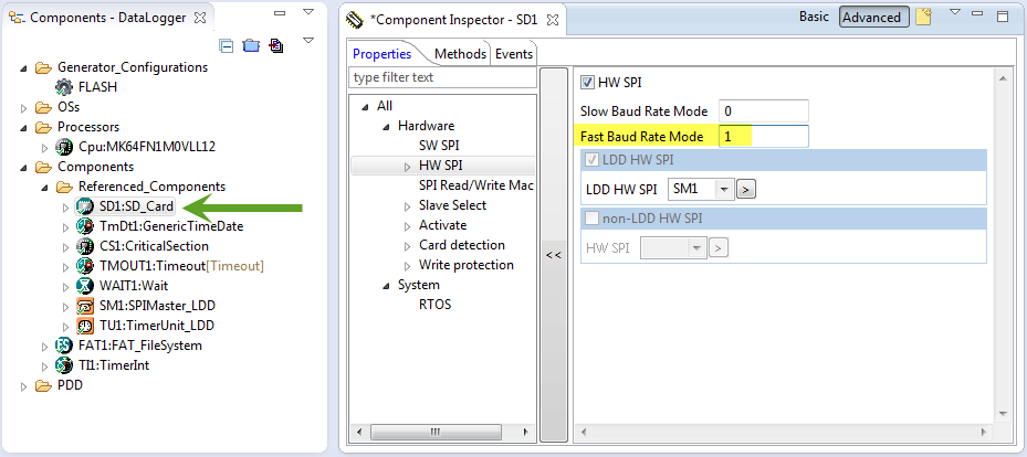
Fast Baud Rate Mode
I order to be able to switch different clock configurations, I need to enable the method SelectConfiguration():
Next I need to assign the chip select pin. This is inside the SD_Card component:
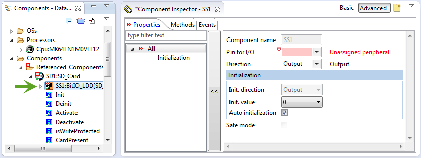
Need to configure SPI Chip Select
The chip select is on PTE4. I can click into the field and type in the name (or to select from the list) to assign it:
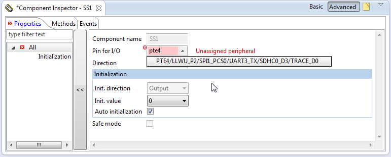
Assigning PTE4 as Chip Select
Next we add the card detection (CD) pin: I select the SD_Card component and enable the pin:

Enable Card Detection Pin
On the FRDM-K64F, the card detection is HIGH active, so I need to deselect the ‘Card Detect is LOW active’:

Card Detect Low or High Active
Realtime Clock
For the SD card I need a realtime clock. Our board does not have this, but I have configured a software realtime clock: GenericTimeDate. As in this tutorial I’m not going to use an RTOS, I add a TimerInt component to the project and configure it for 10 ms:
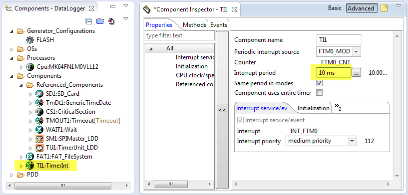
TimerInt component
I need to call the AddTick() method of the realtime clock every 10 ms from above interrupt:
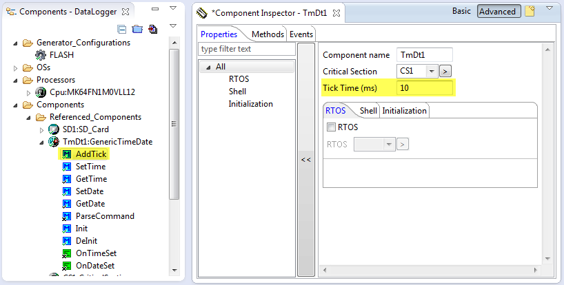
Realtime Clock AddTick() Method
So I generate code:
Generate Code
Then I double-click on the OnInterrupt() event to open the Events.c source file with that event created:

Timer OnInterrupt()
Then I can drag&drop the AddTick() method to the source:
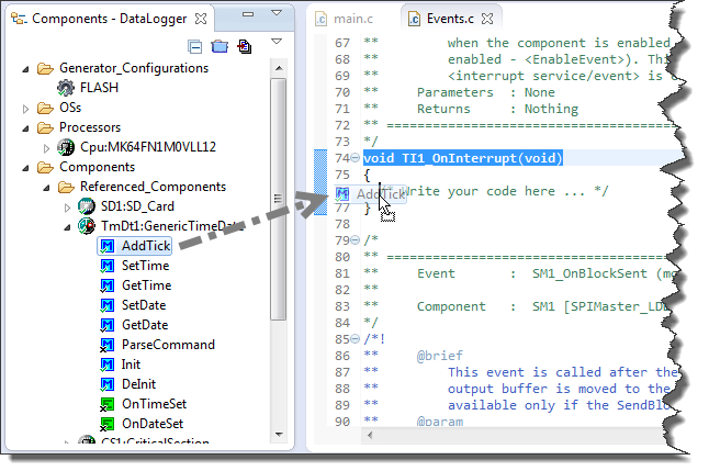
Drag and Drop AddTick() Method
Then save the source changes:
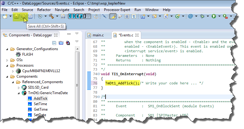
Save Source Changes
The data to log: Accelerometer
With the FatFS I have everything to read and write the SD card. Only the data is missing. In this tutorial I’m using the accelerometer of the FRDM-K64F. So I’m adding the FXOS8700CQ component to the project.
It will ask for the Wait component (which already is part of the project) and automatically adds the GenericI2C component to it. I enable the LDD I2C and add a new I2C_LDD component:
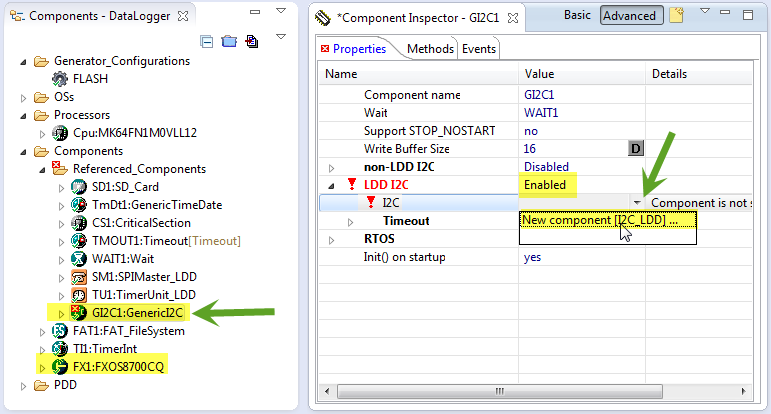
Adding I2C_LDD with FXOS8700CQ
The I2C_LDD component gets configured for I2C0, SDA (PTE25) and SCL (PTE24), with a clock configuration below 100 kHz:
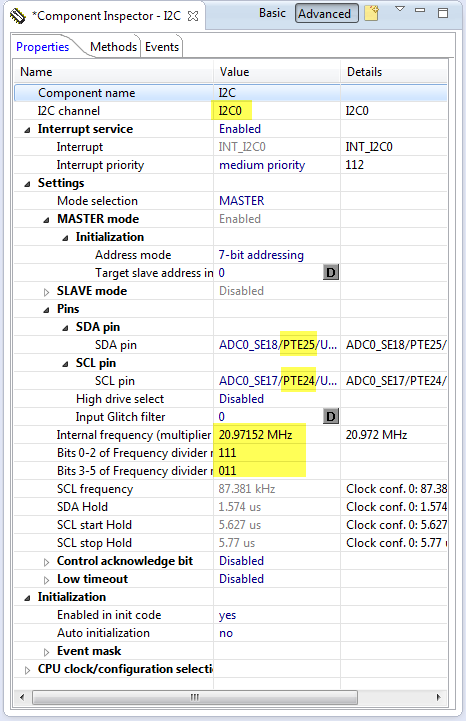
Accelerometer I2C Configuration
Important and not to forget: according to the schematics, the SA1 is LOW and SA0 pin is HIGH, so the device has the address 0x1D:

Accelerometer Slave Address
With this, the hardware configuration is completed, and I can write the application code :-).
Application Code
I add a header file Application.h (context menu with File > New > Header File) and source file Application.c (context menu File > New Source File) to the Sources folder:

Application Files
The header file needs only one function:
/*
 * Application.h
 */

#ifndef APPLICATION_H_
#define APPLICATION_H_

void APP_Run(void);

#endif /* APPLICATION_H_ */
In main.c, I include that header file and call APP_Run:

Main.c calling application
APP_Run() implements my logger loop: initialize the accelerometer and mount the file system. Then it gets the accelerometer data and logs it to a file every second.
First, I need to make sure I have a pull-down enabled for the SD card detection pin (PTE6). Because the BitIO component has no methods to change the electrical characteristics, I’m using PDD macros (see “Low-Level Coding with PDD (Physical Device Driver”)):
  /* SD card detection: PTE6 with pull-down! */
  PORT_PDD_SetPinPullSelect(PORTE_BASE_PTR, 6, PORT_PDD_PULL_DOWN);
  PORT_PDD_SetPinPullEnable(PORTE_BASE_PTR, 6, PORT_PDD_PULL_ENABLE);
For the file system I need to have a file system object and a file pointer. To keep things simple, I’m using global variables:
static FAT1_FATFS fileSystemObject;
static FIL fp;
The APP_Run() is implemented as below:
void APP_Run(void) {
  int16_t x,y,z;
  uint8_t res;

  /* SD card detection: PTE6 with pull-down! */
  PORT_PDD_SetPinPullSelect(PORTE_BASE_PTR, 6, PORT_PDD_PULL_DOWN);
  PORT_PDD_SetPinPullEnable(PORTE_BASE_PTR, 6, PORT_PDD_PULL_ENABLE);

  res = FX1_Enable(); /* enable accelerometer (just in case) */
  if (res!=ERR_OK) {
    Err();
  }
  if (FAT1_Init()!=ERR_OK) { /* initialize FAT driver */
    Err();
  }
  if (FAT1_mount(&fileSystemObject, (const TCHAR*)"0", 1) != FR_OK) { /* mount file system */
    Err();
  }
  for(;;) {
    /* get accelerometer values */
    x = FX1_GetX();
    y = FX1_GetY();
    z = FX1_GetZ();
    /* log it to the file on the SD card */
    LogToFile(x, y, z);
    /* do this every second */
    WAIT1_Waitms(1000);
  }
}
The Err() function is used to indicate an error condition. I can show an error with LED’s or I simply stop application there:
static void Err(void) {
  for(;;){}
}
I want to append the accelerometer data to a file, with date/time information, separated with TABs so I can easily import it into Excel. To construct the strings, I’m going to use the Utility component, so I have added it to my project:

Utility Component
With this, I write my data to the SD card in LogToFile():
- Open the log file (FAT1_open()) with FA_OPEN_ALWAYS (open the file if it already exists, otherwise create the file) and for writing (FA_WRITE).
- Move the file pointer to the end of the file to append the data (FAT1_lseek()).
- Get the current time information from the software realtime clock (TmDt1_GetTime()).
- Construct in a buffer the string to write with time and accelerometer data.
- Write it to the file with FAT1_write().
- Close the file with FAT1_close().
static void LogToFile(int16_t x, int16_t y, int16_t z) {
  uint8_t write_buf[48];
  UINT bw;
  TIMEREC time;

  /* open file */
  if (FAT1_open(&fp, "./log.txt", FA_OPEN_ALWAYS|FA_WRITE)!=FR_OK) {
    Err();
  }
  /* move to the end of the file */
  if (FAT1_lseek(&fp, fp.fsize) != FR_OK || fp.fptr != fp.fsize) {
    Err();
  }
  /* get time */
  if (TmDt1_GetTime(&time)!=ERR_OK) {
    Err();
  }
  /* write data */
  write_buf[0] = '\0';
  UTIL1_strcatNum8u(write_buf, sizeof(write_buf), time.Hour);
  UTIL1_chcat(write_buf, sizeof(write_buf), ':');
  UTIL1_strcatNum8u(write_buf, sizeof(write_buf), time.Min);
  UTIL1_chcat(write_buf, sizeof(write_buf), ':');
  UTIL1_strcatNum8u(write_buf, sizeof(write_buf), time.Sec);
  UTIL1_chcat(write_buf, sizeof(write_buf), '\t');

  UTIL1_strcatNum16s(write_buf, sizeof(write_buf), x);
  UTIL1_chcat(write_buf, sizeof(write_buf), '\t');
  UTIL1_strcatNum16s(write_buf, sizeof(write_buf), y);
  UTIL1_chcat(write_buf, sizeof(write_buf), '\t');
  UTIL1_strcatNum16s(write_buf, sizeof(write_buf), z);
  UTIL1_strcat(write_buf, sizeof(write_buf), (unsigned char*)"\r\n");
  if (FAT1_write(&fp, write_buf, UTIL1_strlen((char*)write_buf), &bw)!=FR_OK) {
    (void)FAT1_close(&fp);
    Err();
  }
  /* closing file */
  (void)FAT1_close(&fp);
}
All what is missing now is the include of the needed header files at the beginning of Application.c:
#include "Application.h"
#include "WAIT1.h"
#include "FX1.h"
#include "FAT1.h"
#include "UTIL1.h"
#include "PORT_PDD.h"
Result
Time to generate code, build and then debug. And it writes file log.txt to the card I can import into Excel:

Data imported in Excel
And visualized in a chart:
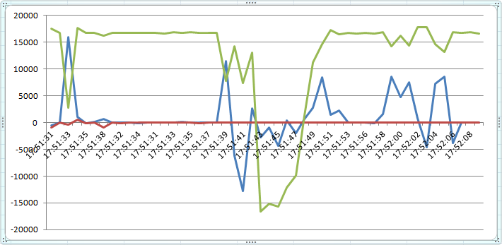
Visualized Data
Summary
Writing a data logger is not that difficult with Processor Expert components. As there are many complex components (file system, SPI, I2C, accelerometer) and drivers involved, it takes some time to set everything up. But once understood, it is very easy to have such a data logger implemented easily for any other hardware.
The tutorial project (with minor extensions) is available on GitHub as reference implementation: https://github.com/ErichStyger/mcuoneclipse/tree/master/Examples/Eclipse/FRDM-K64F/FRDM-K64F_DataLogger
Happy Logging 🙂

Thanks Erich, for this tutorial, it would be possible that you make a tutorial with kl25z frdm, that show some practice using freertos, like serial port?
LikeLike
There is already a tutorial for the FRDM-KL25Z here:
If you want to use FreeRTOS with it: simply add the RTOS and instead of running the logger in a loop, use a task for it.
If it is about using the serial port, I recommend to use the Shell component (there are several examples using it on GitHub).
Does this help?
LikeLike
Excelent tutorial! As usual :).
LikeLike
Great tutorial. I’m learning a lot from this post. I just got a K64F board a few days ago and can’t wait to try it out with the above tutorial. Thank you.
LikeLike
Pingback: Tutorial: Freedom Board with Adafruit Ultimate GPS Data Logger Shield | MCU on Eclipse
Eric, I am getting a Hard Fault error, HF1. What causes this?
LikeLike
That could be caused by many things (NULL pointer, misaligned access, accessing clock domains without clocks enabled).
See
and
LikeLike
Erick
I am trying to do your Logger project with KDS and am getting the following 4 errors:
Description:
Program “arm-none-eabi-gcc” not found in PATH
Location:
Project Properties, C++ Preprocessor Include…/Providers, [CDT GCC Built-in Compiler Settings Cross ARM] options
Type:
C/C++ Scanner Discovery Problem
Description:
Program “arm-none-eabi-g++” not found in PATH
Location:
Project Properties, C++ Preprocessor Include…/Providers, [CDT GCC Built-in Compiler Settings Cross ARM] options
Type:
C/C++ Scanner Discovery Problem
Description:
Generator: FAILURE: Unexpected status of script: Drivers\Kinetis\TimerInt.drv, please contact Freescale support.
Location:
TI1
Type:
Processor Expert Problem
Description:
Generator: FAILURE: Unexpected status of script: Drivers\Kinetis\InitClockGate.prg, please contact Freescale support.
Location:
TSS
Type:
Processor Expert Problem
I am using the latest processor expert values from:
https://sourceforge.net/projects/mcuoneclipse/
I am trying to duplicate your project except that I am using Kinetis Design Studio.
I guess I need to try to do it withour using KDS
LikeLike
The problem about the compiler not found is documented in the KDS release notes (DOC-100441). That issue is that Eclipse tries to parse the sources even if the scanners are not loaded yet. The errors will disappear if you compile your project, so nothing to worry about.
The ‘unexpected status of script’ error indicates that you are you have created a Kinetis SDK project? The problem is that with the Kinetis SDK, the non-SDK components unfortunately do not work. I’m told that this will be improved fro the non-beta version (filtering out the non-SDK components). So you need to create a Processor Expert in KDS *without* the SDK options selected.
LikeLike
Hi, Erich.
Thank you for your post regarding FRDM-K64F Board. It is really helpful. I use Code Warrior 10.6 and it is working. I can see use excel to read the log file. Again Thank you very much.
LikeLike
Hi,
I can’t find the implementation for FX1_* routines in the repository. Where is the Accelerometer access functions coded at?
Thanks,
Zeeshan
LikeLike
That code is generated by the Processor Expert component(s). Have you loaded them (see https://mcuoneclipse.com/2013/05/09/processor-expert-component-peupd-files-on-github/)?
LikeLike
I see that now on my tablet browser (the images were not loading on my other machine). Do the PE components generate source code after you add them to the project or are these shared libraries? I cant seem to unzip the peupd files on my tablet. By the way, I am doing something similar to this tutorial on the K64F but building with keil uVision and i want to write my own low level code to read and write the accelerometer registers over I2C. My existing code seems to work for register reads but i cant seem to bring the accelerometer from stdby to active state (writing to register ctrl-reg1). I was hoping to look at the code behind fx1.* routines to see how it is being managed.
LikeLike
Yes, the PE components create source code. The .peupd files are special packages, you cannot use WinZip or friends to read it. You need to import it into Processor Expert. Note that you might need to power cycle the accelerometer after writing the configuration registers. And you can use Keil with Processor Expert too (mcuoneclipse.com/2013/06/28/using-keil-µvision-arm-mdk-with-processor-expert-driver-suite/), however, it is much easier to use Eclipse (in my view) 🙂
LikeLike
Hi Erich,
Very good tutorial. One note about two errors in SD_SPI.c in the function disk_ioctl. There are two function calls to SD_SPI_SendCmd where the first parm is SD1_CMD9 which throws an error. Think it should be: SD_SPI_CMD9 like everywhere else?
Here is the snippet of code:
case MMC_GET_READ_BL_LEN: /* get Block Length */
if ((SD_SPI_SendCmd(SD1_CMD9, 0) == 0) && SD_SPI_ReceiveDataBlock(csd, 16)) {
switch((csd[5]&15)) { /* READ_BL_LEN is either 9, 10 or 11, end the block size is 2^READ_BL_LEN */
case 9: *(uint16_t*)ptr = 512; break;
case 10: *(uint16_t*)ptr = 1024; break;
case 11: *(uint16_t*)ptr = 2048; break;
default: *(uint16_t*)ptr = 0; break; /* illegal */
}
}
break;
case MMC_GET_SDC_VERSION: /* get CSD Version (1 byte: 1 for 1.xx or MMC, 2 for 2.0 */
if ((SD_SPI_SendCmd(SD1_CMD9, 0) == 0) && SD_SPI_ReceiveDataBlock(csd, 16)) {
if ((csd[0] >> 6) == 1) { /* SDC ver 2.00 */
*ptr = 2;
} else { /* SDC ver 1.XX or MMC*/
*ptr = 1;
}
}
break;
Thank you
LikeLike
Hi Simon,
No, it should be SD1_CMD9 in my view, and this is declared in SD1.h:
#define SD1_CMD9 (0x40+9) /* Asks the selected card to send its cardspecific data (CSD)*/
Are you using the latest components and sources from GitHub?
LikeLike
Actually, I take that back ;-). Indeed, you have found a bug: the component sources were using SD1_ instead of %’ModuleName’%. 😦 I have fixed this now on GitHub (https://github.com/ErichStyger/mcuoneclipse/commit/ee5256992044c0489bd79656bfc7180cd8420dd4), so you could do the same in your component sources if necessary: otherwise have the component named SD1_ and you are ok too.
Sorry for that, and thanks for reporting!
LikeLike
Hello
i really appreciate your work
i’m a total newbie in cortex development i could only make the blink led
i was trying to do the data logger but i’m stuck when i build the program
i’m using KDS with your Processor expert file
C:UsersDevworkspace.kdsdata_loggerDebug/../Generated_Code/SD1.c:818: undefined reference to `SM1_SelectConfiguration’
./Generated_Code/SD1.o: In function `SD1_SetFastMode’:
C:UsersDevworkspace.kdsdata_loggerDebug/../Generated_Code/SD1.c:895: undefined reference to `SM1_SelectConfiguration’
collect2.exe: error: ld returned 1 exit status
make: *** [data_logger.elf] Error 1
LikeLike
Hi Anis,
Have you configured two SPI clock configurations as shown in https://mcuoneclipse.files.wordpress.com/2014/05/spi-clock-values.png ?
And two configurations/attribute sets as in https://mcuoneclipse.files.wordpress.com/2014/05/clock-rate-index-for-attribute-set-1.png ?
But I think your problem is that I have missed to describe a step which is obvious to me (to enable the SelectConfiguration() method).
I have updated the post with following and a screenshot:
“The FatFS driver will change the SPI clock and configuration with the SM1_SelectConfiguration() method, so make sure you have it enabled in the SPIMaster_LDD: If the method icon has the ‘x’ on it, then it means it is disabled: enable it with the context menu:”
Can you check if this solves your problem (after code generation again)?
LikeLike
Erich, the link for the FRDM-K64F Data Logger project is not working for me.
Can you please check it?
Thanks,
David
LikeLike
Hi David,
this link (https://github.com/ErichStyger/mcuoneclipse/tree/master/Examples/Eclipse/FRDM-K64F/FRDM-K64F_DataLogger)?
It works for me?
Erich
LikeLike
Hello,
First thing: the FRDM-K64F Data Logger example doesn’t work out of the box with the last PE Components (2014_11_16) because the FAT1_mount() seems to be changed (in the example it uses 2 parameters, the component want 3 parameters).
Second thing: trying to compile (and run) on KDS using FatFsMemSDHC, but it goes to an unhandledInterrupt when trying to initialize the SDHC:
UnhandledInterrupt() at Vectors.c:67 0x1518
() at 0xfffffff9
SDHC1_Init() at SDHC1.c:613 0x3ea2
Components_Init() at Cpu.c:493 0x28f2
PE_low_level_init() at CPU_Init.c:491 0xca0
main() at main.c:77 0x7ac
the lines in SDHC1.c:
/* Set pin assignments */
/* PORTE_PCR2: ISF=0,MUX=4 */
PORTE_PCR2 = (uint32_t)((PORTE_PCR2 & (uint32_t)~(uint32_t)(
PORT_PCR_ISF_MASK |
PORT_PCR_MUX(0x03)
)) | (uint32_t)(
PORT_PCR_MUX(0x04)
));
Can you help?
Thank you
Giacomo
LikeLike
Hi Giacomo,
yes, indeed, that mount parameter has been changed with FatFs 0.10c (https://mcuoneclipse.com/2014/11/16/updated-mcuoneclipse-components-usb-for-kl24z-fatfs-v0-10c-shell-backspace-and-freertos-trace-hook-configuration/). It should be
if (FAT1_mount(&fileSystemObject, “0”, 1) != FR_OK) { /* mount file system */
I have updated the project on GitHub. I thought I had updated them all, but seems I have missed this on, sorry!
About SDHC interface: I have not used it with the FRDM-K64F, only used SPI. I need to try it out myself.
LikeLike
When I launch debug, I get message like No emulators connected via USB and do you want to connect over TCP IP.
I am new here and I have some basic doubts.
Do we need to use J-Link hardware and connect it to FRDM-K64F?
If not how segger will find emulator. I have my FRDM-K64F connected to my laptop and it shows as MSD only so how it will work as emulator?
LikeLike
You need the Segger V2 firmware loaded on your board, see https://mcuoneclipse.com/2014/04/27/segger-j-link-firmware-for-opensdav2/
LikeLike
Hi, How to import the project in eclipse downloaded from git?
LikeLike
Use the menu File > Import > General > Existing Projects into Workspace.
LikeLike
Pingback: USB with the Freescale FRDM-K22F Board | MCU on Eclipse
Hi Erich,
Thank you for posting this! I’ve worked through the tutorial but when I go to test it afterwards, the Debug Console stops at “Starting target CPU…” and does nothing else. The SD card remains empty.
Do you know what the issue might be?
Thanks!
LikeLike
Hi Andrew, what debug firmware do you have on the FRDM-K64F? It sounds like you still have the mbed one on it, you need to change it to Segger or P&E. Let me know if you need any further information.
Erich
LikeLike
I double checked that I had the Segger debug firmware on the board and also went through your Segger J-Link Firmware for OpenSDAv2 tutorial to install it again and I’m still having the same issues.
LikeLike
hi, even i am having the same issue….debug stops at starting cpu….. no file is written to sd card……. am using segger as explained in tutorial……..
LikeLike
which same issue? I’m affraid that in any case you would need to use the debugger to find out what exactly is going wrong. Are you using my project and sources from GitHub? If not, it could be that you made a mistake or missed a step?
LikeLike
Hello sir,
am a beginner here, After terminating debugging session how to add FatFs component then SD card component? you added critical section also, i want to know how to open that window where you added all these components….
Thank you.
LikeLike
Have you used the menu Processor Expert > Show Views already?
As for FatFS, this one might be helpful for you: https://mcuoneclipse.com/2012/07/30/fatfs-with-kinetis/
LikeLike
sir, i had a problem when i try to debug it with hammer button after cleaning. it is showing
Error: Program “make” not found in PATH
PATH=[c:\Program Files (x86)\GNU Tools ARM Embedded\4.9 2014q4\bin;C:/Program Files/Java/jre1.8.0_31/bin/server;C:/Program Files/Java/jre1.8.0_31/bin;
can you help me, what should i do to avoid it?
LikeLike
Hi sri,
you need a make.exe present in your path. If you are using the GNU ARM Embedded lauchpad, then this does not come with make (or rm). Have a look at https://mcuoneclipse.com/2013/07/20/dyi-free-toolchain-for-kinetis-part-1-gnu-arm-build-tools/ and the section ‘GNU make’.
LikeLike
Thank you so much sir i have followed you till the end but when i built and debugged the code no file is written to my sd card and code shows error at
if (FAT1_Init()!=ERR_OK)
{ /* initialize FAT driver */
Err();
}
its showing
‘void value not ignored as it ought to be’ here, for
if (FAT1_mount(&fileSystemObject, “0”, 1) != FR_OK)
{ /* mount file system */
Err();
}
it is saying
Multiple markers at this line
– Macro usage error for macro: FAT1_mount
– ‘FAT1_mount’ undeclared (first use in this function)
– macro “FAT1_mount” passed 3 arguments, but takes just 2
– each undeclared identifier is reported only once for each function it
appears in
LikeLike
It seems to me that you are using outdated (not matching) FatFS components. The number of paramters to mount() has been changed in the latest version of FatFS. Are you using the latest components from SourceForge(https://mcuoneclipse.com/2014/10/21/mcuoneclipse-releases-on-sourceforge/)?
LikeLike
Thanks for the great tutorial. It is very detailed. I was trying to configure the accelerometer sensor I2C and got stuck, found this tutorial and you gotta love the level of detail in here :). I finally found some time to mess with my FRDM-K64F and with your help its so easy.
LikeLike
Always at your service 🙂
LikeLike
Dear Erich
Congratulations for your excellent work on this blog!
I ran the datalogger application on FRDM-K64F and everything worked as expected. Then I tried to do the same on the FRDM-K22F with no success. When the program executes, the TXT file is not generated and SD card remains blank. I have added a LED_Neg() at the end of the for loop inside APP_Run() and it didn’t blink at all. Some hardware pins were changed according K22F docs ( SM1=SPI0, PTD3/PTD2/PTD1), SS1 in PTC4 and CD1 in PTB16, FX1 slave address is 0x1C. Apparently the program stuck when run the line “if (FAT1_mount (0, &fileSystemObject)! = FR_OK) {/* mount file system */”. I have verified signals MOSI, MISO, CLK and SS on SD socket and there is activity on all pins. Do you have any idea about it? Thank you very much for your attention!
LikeLike
Hi Mauricio,
my FRDM-K22F does not have the SD card socket populated, so I never tried it with that board. On your K22F project, are you using the Timeout component? If yes, are you calling the timout ‘add tick’ method periodically (this is the most common missing part). The other thing might be some issues with the wiring or signals. I believe I have seen some reports that some the signals are used by other parts of the board, but not sure (you need to check the schematics carefully). And can you check that not only that there is some activity on the lines, but the activity is correct? I hope this helps.
LikeLike
Pingback: tinyK20: New Board with micro-SD Card | MCU on Eclipse
Hello again, Erich!
I’m implementing a datalogger with the K22F board, using USB, and saving the data in the
internal flash of the uc.
It’s very strange…. I configured one project to use the uc frequency to operate in 120MHZ (maximum value), using the same configuration that you explained here and the sensor only receives valid data in the GetX() function… so… my Y and Z coordinates it does not refresh the value. Sending the error code. But I think that even the X values are not coherent values…
In other way, configuring a project to work in the default uc frequency, the sensor sends the correct values to my function call… The only thing that I did changed from one project to another is the uc frequency. And I get this strange error… Do you have some idea what can be interfering to acquire this error???
Thanks a lot!
LikeLike
Erich, I solved the problem.
I think that how I as operating in a more high speed bus now, the component need more than 1ms between the acess in his memory.
I added a 10ms wait between every measure and…
My code now is like this:
x = FX1_GetX();
WAIT1_Waitms(10);
y = FX1_GetY();
WAIT1_Waitms(10);
z = FX1_GetZ();
and…
Its working fine! hehe
LikeLike
I have seen similar timing problems with that kind of accelerometer: for example writing a register requires some delay after I can read it. It seems to me that the accelerometer internally has a state machine which might not be very fast?
LikeLike
Hi Erich,
I am using FreeRTOS for data logging application. Design Details are as below.
1. Task1. priority = 5
Task period = 20ms. Which is also the sampling rate of the ADC converted values. I read a few sensor values at this rate.
In this task, I just enable the the ADC conversions.
After the conversion is done, In this ADC0_OnEnd function in Event.c file, I write the converted values to Queue1.
2. Task2. priority = 4
Task period = 100ms
This task dequeues the item from Queue1 and enqueues to Queue2.
3. Task3. priority = 4
Task period = 100 ms
This task dequeues items from Queue2 one by one and writes these to the SD Card.
The problem I am facing is, Queue1 gets filled very soon and I loose few data items. Can you please suggest me what would be right approach to come out of this problem?
LikeLike
Queues are not the right thing to use if you have a lot of data. Because the queues have overhead. It is better to have two buffers: Your Task1 writes into the first buffer the data. When full, it sends a signal to your Task3 to write that buffer to the SD card. The ADC is using buffer2 during that. If full, it signals Task3 that the buffer is full and switches to the first buffer again.
LikeLiked by 1 person
Hi Erich,
Thank you for your valuable suggestion. I am using buffer now.
LikeLike
Hi Erich,
Now my code is somewhat as below.
1. Task1. priority = 5
Task period = 20ms. Which is also the sampling rate of the ADC converted values. I read a few sensor values at this rate.
In this task, I just enable the the ADC conversions.
After the conversion is done, In this ADC0_OnEnd function in Event.c file, I write the converted value to buffer0 which can accomodate many converted values. Once the buffer0 is full, I send a signal to task2 using “FRTOS1_xTaskNotify”.
2. Task2. priority = 4
Task period = NA
This task waits for signal from task1. Once it receives signal, it starts reading the values from buffer(0 or 1, the buffer to be used will be set in ulnotofoedvalue of notifywait routine), and enqueues it into a large queue.
3. Task3. priority = 4
This task dequeues items from Queue2 one by one and writes these to the SD Card.
Problem: Task 2 starts waiting for the signal. Once it receives, it successfully enqueues all the items in the buffer. After this, it again goes to notifywait(). As soon as notifywait() is called, I am getting “HardFault” .
What can be the possible reason for this?
Thanks in advance
LikeLike
Your hard fault is likely caused by a Null pointer exception. Are your queues created upfront?
Additionally, I see you are still using queues (in Task3): again: using queues in your case might add too much overhead.
Additionally, I recommend you do not run the sampling at full speed intially: for testing, do a few samples per seconds first, then increase speed once everything is working.
LikeLike
Hi Erich,
call to – vPortStartFirstTask(); /* Start the first task. */
is causing the HardFault. But everything works fine before. Why does it happen only after the task goes into waitnotify state?
LikeLike
Do your task have an endless loop implemented (for(;;) { … })?
Can you use the Processor Expert hard fault component to find out what is going on (https://mcuoneclipse.com/2012/12/28/a-processor-expert-component-to-help-with-hard-faults/)?
LikeLike
Hi Erich,
Yes, the tasks are in the for(;;){ } loop. I am using PE componenet Hardfault.
According to hardFault component,
stackedpc = 0x24c2. This points to function AdcLdd1_CreateSampleGroup().
371 if (SampleGroupPtr[0].ChannelIdx >= AdcLdd1_CHANNEL_COUNT) { /* Is channel index out of range? */
000024c0: ldr r3, [r7, #8]
000024c2: ldrb r3, [r3, #0]
000024c4: cmp r3, #1
000024c6: bls.n 0x24cc
372 return ERR_PARAM_INDEX;
stacked lr = 0x1d97. This points to a function in AdcLdd.c (ADC0_HWEnDi)
151 (void)AdcLdd1_CreateSampleGroup(AdcLdd1_DeviceDataPtr, (LDD_ADC_TSample *)SampleGroup, 1U); /* Configure sample group */
00001d88: ldr r3, [pc, #40] ; (0x1db4 )
00001d8a: ldr r3, [r3, #0]
00001d8c: mov r0, r3
00001d8e: ldr r1, [pc, #32] ; (0x1db0 )
00001d90: movs r2, #1
00001d92: bl 0x2488
152 (void)AdcLdd1_StartSingleMeasurement(AdcLdd1_DeviceDataPtr);
00001d96: ldr r3, [pc, #28] ; (0x1db4 )
00001d98: ldr r3, [r3, #0]
00001d9a: mov r0, r3
00001d9c: bl 0x243c
Looking at the above values, I am not able to figure out at all what went wrong.
The function calls in KDS are as follows.
xPortStartScheduler() –> vPortStartFirstTask() –> signal handler called –> HF1_HandlerC()
Both of them are not matching. So I am not exactly able to make out what is going on. 😦
LikeLike
I recommend that you reduce the complexity of your problem: disable everything which is not critical for now. Get a running configuration, and then re-add things again. For example disable the ADC part, just run one task, etc. Then slowly add things again to see what is your problem. Otherwise you are jumping around and you are not able to solve your problem in a systematic way 😦
LikeLike
Hi Erich,
I’m trying to use your tutorial to implement datalogger with FRDM-K64F and CodeWarrior 10.6. For now I use only couple of functions just to create a file and write short string into it. I configured components as you recommend but still during debugging my code stucks on the while loop:
while(!SD1_DataReceivedFlag){}
from function SD1_SPI_WRITE_READ() which is called from FAT1_Init(). My main.c:
static FAT1_FATFS fileSystemObject;
static FIL fp;
int main(void)
{
UINT bw;
FRESULT res;
/*** Processor Expert internal initialization. DON’T REMOVE THIS CODE!!! ***/
PE_low_level_init();
/*** End of Processor Expert internal initialization. ***/
/* Write your code here */
PORT_PDD_SetPinPullSelect(PORTE_BASE_PTR, 6, PORT_PDD_PULL_DOWN);
PORT_PDD_SetPinPullEnable(PORTE_BASE_PTR, 6, PORT_PDD_PULL_ENABLE);
FAT1_Init();
res = FAT1_mount(0, &fileSystemObject);
res = FAT1_open(&fp, “./log.txt”, FA_OPEN_ALWAYS|FA_WRITE);
//FAT1_write(&fp, “hello”, 6, bw);
//FAT1_close(&fp);
I’ve checked the references of the SD1_DataReceivedFlag and this macro exists only in 2 functions generated from SD_Card component and it’s not being set true in the whole project. Am I supposed to change the code in any place or add the interrupt service routine to set the flag?
LikeLike
Hi Marcin,
When I tried Data logger on K22F board, I was stuck at the same place. After investing lot of time, I found out that I was using the wrong pin. After I corrected, it started working perfectly. Can you please cross verify all the pins used. Ex: MOSI, MISO, CD, CS, CLK.
LikeLike
Yes, I have been told that different revisions of FRDM-K64F boards have different pin assignments: https://developer.mbed.org/questions/5419/FRDM-K64F-NRF-CE-is-no-longer-connected-/
LikeLike
Hi Marcin,
Could you give Kinetis Design Studio a try with https://github.com/ErichStyger/mcuoneclipse/tree/master/Examples/KDS/FRDM-K64F120M/FRDM-K64F_Demo?
I ask because for Kinetis I had to move away from CodeWarrior, as all the new devices are not supported with CodeWarrior any more. And in my view KDS is much better than CodeWarrior in most parts. And I have all my latest projects in KDS too. As CodeWarrior, KDS is Eclipse based, so should be very easy for you.
If you still want to get it in CodeWarrior: The SD1_DataReceived flag is set by the SPI interrupt:
void SM1_OnBlockReceived(LDD_TUserData *UserDataPtr)

{

  /* Calling inherited event */

  (void)UserDataPtr; /* unused */

  SD1_DataReceivedFlag=TRUE;

}
in SD1.c. If this flag does not get set, it means that your SPI interrupt is not firing. Maybe your pins for SPI are wrong (check the schematics and revision of your board), or your interrupts are not enabled.
The other usually missing part: if you are using the Timeout component, make sure you are calling its AddTick() method.
LikeLike
Thank you Vishal and Erich:) the SM1_OnBlockReceived event occured to be empty and after adding the line which sets the flag , everything works fine. Anyway, I wonder how big the maximum buffer size which I can transfer via SPI on microSD card is.I need to obtain quite high sample rate (e.g above 20kHz) to store data form ADC hence my question.
Best regards,
Marcin
LikeLike
Hi Marcin,
it has this data interface:
bool SD1_SendDataBlock(byte *data, byte token, word nofBytes)
word is unsigned short, so you can send up to 64KByte of data.
However, the block size inside FatFS is usually 512 Bytes, so data read/writes are of that size.
As for your buffering, I recommend something in the area of 5-10 KByte (ringbuffer).
As for speed: I have recently fixed a bug on GitHub:
https://github.com/ErichStyger/McuOnEclipse_PEx/issues/8#issuecomment-129472776
which improves the speed 🙂
Erich
LikeLike
Hi Erich,
I’ve imported the PE library from your Sourceforge profile to my CodeWarrior. Does this package already include the fixed version of SD1.c (in terms of speed)?
I have another question. You think that using your component RingBufferUint8 to buffer data form ADC is reasonable? Please give me some clue how to use it in simple ADC->SD application. I’m also afraid that the utility functions converting number to string may consume a lot of processor time/resources and cause decreasing of sampling rate. Is it possible to fill the buffer with numbers and then convert it to string as a whole, so that I don’t need to do it with every single ADC data? I think in such situation, separating values to obtain e.g column of data may become problematic, because of ‘\0’ or ‘\n’ issue… Maybe there is a way to write data to SD directly in number format? Maybe changing the file file extension in f_write from .txt to .dat or .csv can make a difference? But still, I have to take into account the format of the FAT functions’ arguments and they expect to operate only on strings (?). If you give me any hints I’ll be very thankful!
LikeLike
Hi Marcin,
yes, I have not produced a new release of the components on SourceForge because I have several smaller items pending I want to have included too. If you subscribe to the project on SourceForge, you will receive a notification once there is an update. And I will post a short blog article too. Until then, you can use the the .PEupd file from here: https://github.com/ErichStyger/McuOnEclipse_PEx/issues/8
LikeLike
Hi Marcin,
about your question writing data to the SD card: Yes, you can use the RingBuffer for storing values and getting them out. And I would recommend to store the numerical values (not the string values): the numerical numbers need much less space and are more efficient, e.g. “123456” takes 4 bytes, while as a string it will be 7 bytes (including the zero byte).
And of course you can write the numbers in ‘binary’ format to the disk too. Here again: you have twice the throughput than writing text values.
And f_write does not care about the file extension: it always writes the data ‘as is’. So you can write directly the numbers in your own format, then read it on the PC with your own small program to transform it back into text format.
Or you might do what I did in another project: here we had to do lots of ADC conversion tool (see hwww.geometh.ethz.ch/uav_g/proceedings/eck and blogs.freescale.com/mcus/2010/10/buried-treasure-unmanned-helicopters-tower-cards-and-codewarrior-for-microcontrollers-10/). Here I write the data in binary/number format. And I have a routine (as a shell command) in the application (not on the PC) which can be used to convert the binary file into a ‘readable’ text file.
So I write it in binary/number format during data sampling, and once it is over, I convert the file into the text format. That way I do not need a program on the host PC.
I hope this helps.
LikeLike
Thanks for your support Erich, I really appreciate it:)
LikeLike
Hi Erich,
I had couple of questions.
1. When writing to micro SD card using SDHC, having 512Kb buffer is recommended. but when writing using SPI, is it advisable to use the same. I read a bit on SDHC and SPI and found out that it is preferred only for SDHC. Please corect me if I am wrong.
2. I have come up with my own custom board using FreeScale K22FN512. I have connected 32KHz oscillator to RTC pins of the MCU. When I generate code, In CPU_Config.h file ,
/* System clock initialization */
#define STARTUP_RTCOSC 0x01U /* RTC oscillator not initialized */
it is set as 1 because i config the same in PE.
But during hardware initialisation, I get a fault.
In CPU_Init.c file,
/* System clock initialization */
#if STARTUP_RTCOSC
/* SIM_SCGC6: RTC=1 */
SIM_SCGC6 |= SIM_SCGC6_RTC_MASK;
if ((RTC_CR & RTC_CR_OSCE_MASK) == 0u) { /* Only if the OSCILLATOR is not already enabled */
RTC_CR = (uint32_t)((RTC_CR & (uint32_t)~(uint32_t)(RTC_CR_SC2P_MASK | RTC_CR_SC4P_MASK | RTC_CR_SC8P_MASK | RTC_CR_SC16P_MASK)) | (uint32_t)STARTUP_RTC_CR_SC_VALUE);
RTC_CR |= (uint32_t)RTC_CR_OSCE_MASK;
RTC_CR &= (uint32_t)~(uint32_t)RTC_CR_CLKO_MASK;
}
#endif
As soon as the code enters if statement, I get the fault.
if I set STARTUP_RTCOSC to 0, I donot get the error. What might the reason be for this?
LikeLike
Hi Vishal,
1) Do your really mean 512 *kilo* bytes? I think 512 bytes is more appropriate. And not sure which buffer you mean: but what you need is a way to send the data (regarless of SPI or SDHC) as uninterrupted as possilble.
2) What kind of fault do you get there? But I think you get a fault because you are accessing the RTC peripheral domain: you need to power the RTC (there is an external pin for this) and enable clocks, otherwise you will run into a hard fault. I guess you missed to power the RTC vcc.
Erich
LikeLike
Hi Erich,
1. Sorry. I meant 512 bytes. I just want to know why did the number 512 come? it could have been 1024, or 100 or something like that. Why specifically 512.
2. I am not able to figure out which is the external pin to power the RTC.
Also do you have any sample code or PE component to use on chip RTC module?
LikeLike
Hi Vishal,
About 1): the number 512 comes from the macro _MAX_SS (see ffconf.h). This defines the internal buffer FatFS is using, and FatFS is reading/writing such an amount of buffers. All my designs are using 512 bytes, and I have not tested higher numbers. If you search for _MAX_SS, you will find the places where it is used.
Erich
LikeLiked by 1 person
Hi Vishal,
About 2) It is the VBAT pin: is it powered?
And Processor Expert has the RTC_LDD (or RTC) component.
LikeLiked by 1 person
Hi Erich,
Both answers are right. Everything works fine now Thanks again.
LikeLike
GREAT 🙂
LikeLike
Hi Eric,
i have k64f board. I tried this tutorial. I updated components to 2015-07-05 from sourceforge.net but Fat1_mount command need 3 arguments till. I tried FAT1_mount(&fileSystemObject,0,1) and FAT1_mount(&fileSystemObject,0,0) but i coudn’t pass mount. how can i pass this part ? Thank u for help
LikeLike
Oh yes, FatFS has changed that API in a later version. Now you need to pass the drive as a string, plus there is an option to mount immediately (1) or not immediately (0).
You can use this:
FAT1_mount(&fileSystemObject, (const TCHAR*)”0″, 1)
I have updated the post to reflect that, sorry that I missed to update it for the latest FatFS.
LikeLike
Thank u so much. We learn freescale by you. God bless you. Thank you again.
LikeLike
Hey Emreoz,
I agree with you. Erich has been so humble and helpful. he responds to all the queries.
Thanks a lot. You are like a god.
LikeLiked by 1 person
Hi!
How are you?
I make my code for my project, and when I build the project appear me this error and I don’t how do to remove it:
make: *** [NUEVO.elf] Error 1
(NUEVO is the name’s project)
Error code I think is not, but don’t know where are the error!
Please help me!
LikeLike
Hi Bruno,
check the Console View output as this view gives all the details about the error(s). The ‘Problems’ view only shows the ‘parsed’ messages.
LikeLike
I tried to run the FATFS using the SDHC on a FRDM-K64F board, but kept getting a hard fault in PE_low_level_init(); I tracked it down to the line in SDHC1_Init() that configures the pins:
PORTE_PCR2 = …
It turns out, the SDHC bean doesn’t properly enable Clock Gate to the ports being used for it’s pins. The right fix would be to add:
SIM_SCGC5 |= SIM_SCGC5_PORTE_MASK;
above the lines that configure the pins. As a workaround, the LEDs happen to be on PortE as well. So, I simply re-ordered the components so that the LEDs would enable the clock gate before SDHC initializes, solving the problem.
LikeLike
Thanks for sharing that tip! Indeed, I would have expected that the InitSDHC component would enable the clocks, or have a setting for it.
LikeLike
Hi Sean, I tried your solution and used init_GPIO to enable the clock gate but it was not working. it is appreciated if you could share the sample code.
LikeLike
I’m having some trouble running this on my K64 using KDS and PE. When I reach the point of adding the FAT FileSystem, GenericTimeDate, and SD_Card components I am presented with a message from PE stating that ‘The component “SD1” uses another shared component for item “HW SPI”. ‘
Both of the components presented by PE state that they are unsupported on MK64FNM0VLL12. As such, I have not been able to correctly configure the SPI interface. Any suggestions on what I might be missing?
Thank you!
LikeLike
Have you created that project with the Kinetis SDK option enabled? Note that the Kinetis SDK does not support these components. You need to create the project without the Kinetis SDK enabled.
LikeLike
Hi Erich
I am trying to port your data logger example to an MK20FX512 based board with microSD card. I am using CodeWarrior version 10.6 and your most recent components release.
Your tutorial explicitly uses the SPIMaster_LLD component, but in my case I cannot seem tot be able to use that component. For example, when I insert the FAT_FileSystem the tools guides me throught the various shared component insertion but only gives me the choice of HWSPI and SynchroMaster for the SPI peripherals. I just cannot get the option of selecting the SPIMaster_LDD.
I also tried to manually insert the SPIMaster_LDD before inserting the FAT_FileSystem so as to be able to choose to use an existing component, but the existing instance of my SPIMaster_LDD did not even show up as an option. Any clue as to what is the issue?
LikeLike
Congrats! Your blog is really helpful!
But I’m having a minor issue. I’m using a RD-KL25-AGMP01, and just built a datalogger based on your tutorial (some minor changes were necessary).
But when I get the accelerometer data something really strange happens.
You code is:
for(;;) {
/* get accelerometer values */
x = FX1_GetX();
y = FX1_GetY();
z = FX1_GetZ();
/* log it to the file on the SD card */
LogToFile(x, y, z);
/* do this every second */
WAIT1_Waitms(1000);
}
When I debug, step-by-step, it logs all the values correctly (x,y,z). But when I hit play (standlone running) the y value is always 0. I’ve noticed that is something related with the data acquisition time, because when I add a little delay before each data acquisition, it works fine. So, I end up with the following:
/* Get accelerometer data*/
x = FX1_GetX();
WAIT1_Waitus(1);
y = FX1_GetY();
WAIT1_Waitus(1);
z = FX1_GetZ();
Do you know why is that happening? Do you have a better solution?
Thanks!
LikeLike
Yes, I had seen something like that (cannot find the post about this right now). But it was around writing a register and reading it again.
It might be related to the I2C clock frequency too.
LikeLike
Instead of an SD card, I have a 1GBit SPI flash chip on my custom embedded board. Will the above example port directly to my system or are there some caveats I should be aware of?
LikeLike
SD, microSD and eMMC cards have a special controller, and this example works for this. If you are using a normal SPI FLASH chip, you have to write your own low level access routines. So this example does not work directly for your chip, but you can adopt it.
LikeLike
Understood. My embedded system is for a data logging application. Need to record sensor events along with a time stamps. If I am going to take the approach of writing my own low level drivers for reading/writing to my SPI memory, can I still use your FAT file system component to manage my files or does that only work with SD cards etc that have the special controller? The alternative is a simple approach of writing the data directly to the flash memory and keep track of the memory address for subsequent writes etc.. which is not as clean from a user point of view. Would appreciate your comments. Thanks
LikeLike
Hi Raoul,
right now the FatFS component supports SD/eMMC SPI/SHDC and USB MSD. I was planning for adding internal FLASH memory support, but not yet for external Flash. You could use the component, but then you need to disable code generation for it (see https://mcuoneclipse.com/2012/03/23/disable-my-code-generation/) and then you can add your own low level routines. I could easily add a property to the component not to generate/use any low level disk functions: that would be easier for you to add the low level disk functions. What do you think?
LikeLike
Just another thought: using a file system for data logging is a good idea, but keep in mind that the file system comes with some overhead. So if you really need to store data fast, then low level block access might be the way to go (and not using a file system).
LikeLiked by 1 person
I would really like to see in some future FatFS release support for external flash memory – please keep me posted on that. But since time is critical for me right now – I think I will stick with the simplest approach possible and that is to write my own low level driver for block reads and writes to the flash memory. Thanks for your input.
LikeLike
Hi Raoul,
I commit changes and updates on GitHub here: https://github.com/ErichStyger/McuOnEclipse_PEx. You can get notifications from there.
Additionally I post usually an article with main features about new components as here: https://mcuoneclipse.com/2016/05/08/mcuoneclipse-components-8-may-2016-release/
So if you follow this blog, you get posted.
LikeLike
Got it. I just joined MCU on Eclipse and was not clear on the protocol.
LikeLike
Hi Eric
I have an question that is unrelated to this topic. Do you have an email address that I can contact you with?
LikeLike
see https://mcuoneclipse.com/about/
LikeLike
Rather than reinventing the wheel so to speak, do you happen to have available a component to read from and write to external SPI flash memory chip? I am using a 1 GBit Micron N25Q00AA13GSF40G Serial Nor flash memory chip.
LikeLike
No, I don’t have a driver for this one.
LikeLike
Hey Erich, I’m followed the project on KDS 3.0 with the latest components created by you. everything seems to follow up until i get to the part where configuring the SPI component. I’m not getting the same component as what the guide is shown to get. KDS seems to suggest synchromaster[HWSPI] components. This component does not allow to select the attribute list and or set automatic initialisation
LikeLike
Hi Abdul,
yes, that component has evolved a bit after writing that article. The HWSPI component (SynchroMaster) is even easier to use.
I’ll add a few more screenshots and steps in the next minutes if possible so you can follow that.
Erich
LikeLike
Hi Abdul,
I have added a few more screenshots covering the SynchroMaster case, I hope this is useful.
You might check out this example project: https://github.com/ErichStyger/mcuoneclipse/tree/master/Examples/KDS/FRDM-K64F120M/FRDM-K64F_Demo
Erich
LikeLike
Hi Erich, I am following your tutorial but it seems that some components slightly changed since you wrote it. I am getting some errors which hold me from generating Processor Expert code :
“at line 2682: “Shell”/Shell has not assigned the component (file: Drivers\sw\FAT_FileSystem.drv)”
Do you know where it could come from ?
I would like to set up my data logger rapidly and Im not sure if the best way do this is to use Processor Expert components or go baremetal.
Best regards,
Martin
LikeLike
Hi Martin,
yes, things have evolved a bit over time. To ask the obvious thing: are you using the latest component version from GitHub?
Because that message usually comes up with mixing very old with newer components, or that not all components are installed.
If this does not help, maybe you can send me your project (KDS? CW?) to the email address in the About page of this blog and I try to have a look.
Erich
LikeLike
I was using the may version, I downloaded the one you uploaded 5 days ago and indeed everything works well now !
Thank you for your help, your website, and all those very helpful components.
Regards,
Martin
LikeLike
Hi Martin,
ah, thanks for checking and especially for reporting back, appreciated!
Erich
LikeLike
Hi Erich,
I was wondering : how do you chose the size of the buffer where to write the strings ? Here you set it to 48 bytes but is there a particular reason for this ?
Martin
LikeLike
Hi Martin,
No particular reason, except large enough to hold the string to be written to the SD card.
Erich
LikeLike
Ok that’s what I thought 🙂
Thank you,
Martin
LikeLike
Hi Erich,
I am implementing the FATFS on my custom K22FN hardware and came up with a problem you might not know about yet.
I am using the latest component release, 21-09-2016, I suspect something changed from when this tutorial was written.
I get a compile error on this line in LogToFile:
/* move to the end of the file */
if (FAT1_lseek(&fp, fp.fsize) != FR_OK || fp.fptr != fp.fsize) {
Err();
}
The error is ‘FIL’ has no member named ‘fsize’. there is an fsize in the FILINFO struct that seems like it would be what we would want to use.
I changed the fp.fsize to be the macro FAT1_f_size(&fp), and the errors went away.
/*fixed line*/
if (FAT1_lseek(&fp, FAT1_f_size(&fp)) != FR_OK || fp.fptr != FAT1_f_size(&fp)) {
Brynn
LikeLiked by 1 person
Hy Brynn,
yes, the latest FatFS does not provide access to fp.fsize any more. Instead, you should use
  if (FAT1_lseek(&file, f_size(&file)) != FR_OK || file.fptr != f_size(&file)) {

    Err("failed lseek\r\n");

  }
So your fix is correct, thank you!
LikeLike
Hi Erich,
In implementing the FATFS on my K22FN custom hardware I have observation and a question:
I have 3 different peripherals hooked to SPI0, with three chip selects (pcs0,pcs1, and pc2).
the SPI Master component lets me set that up just fine, but the FATFS didn’t like that and I had to take pcs0 out of the SM1 component and let the SS1 sub component of SD1 handle it.
It seems like the SM1 could handle it just fine.
The question I have comes from sharing the SPI port with other peripherals.
what are the rules I need to follow to keep from corrupting the FATFS?
my pcs1 is a like an open drain HC595, and the pcs2 is a SPI Flash chip.
rarely I will need to change the 595’s outputs, but in an interrupt. I can probably set a flag in the interrupt for later updating of the 595 when the FATFS is not busy, but what is a good way to know that the FATFS is busy?
Also, am I supposed to change the ‘HW input buffer size’ in the SM1 to 512 for the FATFS?
(and the ‘HW output buffer size’ too)
Brynn
LikeLike
Hi Brynn,
I had that challenge with multiple SPI slaves on the same bus, described in https://mcuoneclipse.com/2014/11/22/tutorial-playing-mp3-files-with-vs1053b-and-frdm-board/.
Basically you need to ensure that only one task/thread is accessing the bus. Usually you should not do this from the interrupt itself, but from a thread task.
In the above article/example (check out the github code) I’m using a pair of VS_OnSPIActivate() and VS_OnSPIDeactivate(). They get called too from the FatFS/SD card code (SD1_OnActivate() and SD1_Deactivate()).
VS_OnSPIActivate() does allocate a semaphore to ensure mutual exclusion for the SPI access. Have a look at https://github.com/ErichStyger/mcuoneclipse/blob/master/Examples/KDS/FRDM-KL25Z/FRDM-KL25Z_MusicMaker/Sources/VS1053.c
You can use that semaphore to know if FatFS (or anything else) on the bus is busy.
And you don’t have to change the buffer size in SM1.
I hope this helps,
Erich
LikeLike
Hi
I’ve downloaded your components and installed correctly, but when i add them to my project (i’m using a PExpert without KSDK) and compile i get errors because missing libraries cannot be found.
I’d like to add the SD card functionality to my project but i don’t understand why i get these compilation errors when i add these specific components.
Can you help me?
Thanks
P.S.
I’m using a K64 on a FRDM and with the procedure taken from here it work perfectly for me
The only problem is that this example use components with KSDK 1.20 and my project was made without KSDK 1.20.
LikeLike
Hi Fabrizio,
are you using the project from https://github.com/ErichStyger/mcuoneclipse/tree/master/Examples/Eclipse/FRDM-K64F/FRDM-K64F_DataLogger? I think I might not have updated that one with the latest components, let me check.
Erich
LikeLike
Hi Erich, I’m trying to port this across to a K22 using SPI as the interface to the FAT_FileSystem. One question I have though is that during the SD1_Init routine, I’m finding that the SD1_SPI_WRITE(SD1_DUMMY) takes a long long time as the SD1_DataReceivedFlag doesn’t seem to be being set frequently. As far as I can see, the only place the SD1_DataReceivedFlag is set is part of the interrupt routine for the SPI. Are there any special setup requirements for the SPI aside from what is highlighted in this tutorial? Could there be some gremlins related to the K22 which would make porting across more difficult? The SOUT/SIN/SCK and CS/CD pins have been correctly specified so I’m fairly happy its not a pin mux configuration error.
LikeLike