
Thanks for all the feedback and suggestions so far on the tinyK20 project! I’m proud to present the next iteration of the universal microcontroller & debugger board based on the Freescale Kinetis K20 USB microcontroller:

tinyK20 Board
Changes from the earlier version (see “tinyK20 Open Source ARM Debug/Universal Board – First Prototypes“):
- Replaced the K20 crystal with one having a smaller footprint.
- Added Micro SD card socket on the back (same socket as on the FRDM-K64F or FRDM-K22F).
- Because SD cards can draw more than the 120 mA the K20 internal 3.3V provided, there is a footprint on the backside of the board to add an extra DC-DC converter.
- Moved reset button and headers.
- First version with transparent enclosure.
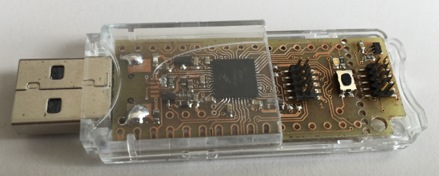
tinyK20 ‘Thumb’ Drive Version with transparaent Enclosure
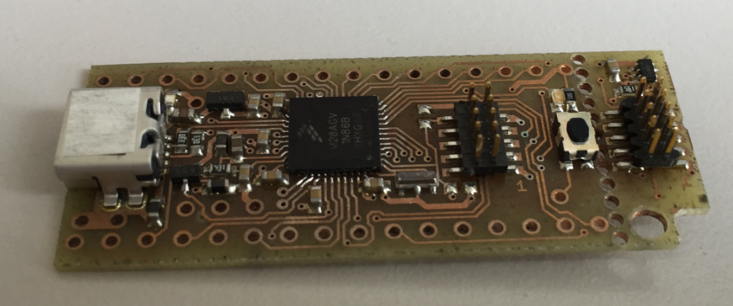
tinyK20 ‘Cable’ Version
The new version includes a micro-SD card socket on the bottom side of the board. Because the 3.3V DC-DC converter of the K20 only can drive 120 mA, there is a footprint on the back to add a 5-to-3.3V DC-DC converter.
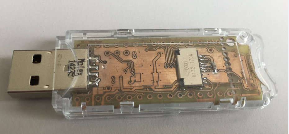
tinyK20 Thumb Drive Bottom side

tinyK20 ‘cable’ version with SD Card inserted
If the breakable debug part of the board is removed, the SD card can be easily removed. But it works well with the ‘full’ board, but of course is not that user-friendly.
One thing we will probably do for the first ‘production’ run is to move the capacitor under the SD card. Personally, I prefer the ‘USB cable’ version: I have a mini-USB cable already, that makes it easier to move the board, say to the robot to be programmed, as the SWD flat cable should be only a few centimeters long. My vision is to use a transparent shrink-tubing around the board instead of a special case. What do you think? Which version would you prefer: the ‘cable’ or the ‘thumb’ version?
Happy tinying 🙂
Links
- First concept: https://mcuoneclipse.com/2015/04/21/proof-of-concept-open-source-arm-swd-debug-and-general-purpose-board/
- First prototype boards: https://mcuoneclipse.com/2015/05/17/tinyk20-open-source-arm-debuguniversal-board-first-prototypes/
- Thumb drive enclosure: https://mcuoneclipse.com/2015/05/20/tinyk20-usb-thumb-drive-enclosure/
- Material on GitHub: https://github.com/ErichStyger/mcuoneclipse/tree/master/tinyK20

Hi Erich!
Nice one project! For me cable version is more universal. As i can see it is doublesided project. Ho did you make layers interconnection?
LikeLike
Hi Alexey,
yes, it is a dual layer board. The vias/interconnections are done outside the university. They put a materil into the holes, and then transform it in a bath to cupper connections.
LikeLike
Hi Erich
Cable version +1
Is it practical to add an option to connect a serial port to the target board in the way that the FRDM boards do? Then your new board could act as a console to the target board while developing. Even if you leave the software till later.
Can the target be powered from this board? e.g. using the optional regulator?
AFAIK the schematics in GitHub must be for an earlier version.
FYI I have been using this connector for SWD, power and UART on my targets – it is small and low profile and surprisingly robust. tinyurl.com/oyk5kbd If it was my design, I’d add one to the K20 board – I’ll provide pinouts if you like, and we can set the new standard 😉
LikeLike
Thanks for voting 🙂
About that serial port: you mean to use the board as UART(3.3v)-to-USB CDC bridge? Yes, absolutely. Same functionality as the FRDM board do.
The 3.3V are provided on the SWD connector, but this is not intended to power lots of current. Of depends on the optional regulator.
Schematics: yes, I had no time to update the files yet. About that connector: so this is what you put on your boards as debug and serial port? So you build a SWD-to-ThisConnector in order to debug the board? My current thinking is that the normal SWD connector (5×2 pins) is more of the standard, and if I want serial over it, I could use e.g. the Segger Realtime terminal functionality instead?
LikeLike
It’s a good, small connector for targets. Pin headers are too big for me. It often provides enough GPIO plus power, and when debugging I can wire it to the Segger JLink and break out the UART to an FTDI TTL-232R-3V3 cable. Photo: https://dl.dropboxusercontent.com/u/472780/debug_setup.jpg
I haven’t met Segger Realtime before. Does PE support it?
LikeLike
Hi Charles,
thanks for sharing that picture. So it is basically a SWD connector plus UART RX/TX. That’s a good idea. As for doing this with the tinyK20, you could use the tinyK20 to debug your other board (with the normal SWD cable), plus use two wires for the RX/TX line which you would connect to the pins routed on the outside of the tinyK20.
LikeLike
Hi Charles,
about Segger Realtime Terminal: I have posted an example here (without PEx, using the SDK): https://github.com/ErichStyger/mcuoneclipse/tree/master/Examples/KDS/FRDM-K64F120M/FRDM-K64F_Segger_RTT
But I have it used in another project with K22F with Processor Expert. It is just a bunch of source files. I planned to write a blog post about it, but well, not enought time these days …
Have a read as well here: https://www.segger.com/jlink-real-time-terminal.html
LikeLike
The schematics have been updated and are available on https://github.com/ErichStyger/mcuoneclipse/tree/master/tinyK20/Board
LikeLike
Hello,
Very nice project. And it’s awesome you are releasing the source files. Do you also plan to release the gerber files so one can make the boards at home or using an online fab service ?
I would be really interested to try to make a small batch, eventhough it’s still a prototype.
Cable version is easier to use on desktop (most common use), but having an USB-stick version is easier when travelling. If you could keep both footprints, that would be great.
Thanks you also for all the posts on this blog, they’re really helpful
LikeLike
We plan to produce an initial batch of 50 boards populated with the components, with solder-stop mask, etc. The project is made with Eagle, so the plan is to share the Eagle files so everyone could make his own board.
It could be interesting to produce a higher amount of boards (maybe after the 50 initial ones), if there is enough demand. But not sure if there will be enough demand?
LikeLike
I prefer cable version ! 😀 .
I will surely buy more then one if you go in production . Do you have an idea when it will be release ?
LikeLike
Hi Max,
I would like to use it in the class/course in the next semester. We have not sorted out the logistics, but the idea is for the Sept timeframe.
LikeLike
At the risk of becoming boring – if you’re doing another PCB iteration, why not hook up a K20 UART to the 10-way connector pins 6 and 8, through series resistors so you can choose whether to use this functionality or not…
LikeLike
Not boring at all! Need to check, but I believe that might be very difficult with using a dual layer board only…..
LikeLike
Hi Charles,
here is what we are looking into: adding two vias/holes on the detachable programming PCB part, connected to SWD pins 6 and 8 (or could other pins be used?). Then you can connect yourself these vias with two wires to the UART RX/TX of the K20 which are available on the two outer side rows of the board. That way you can connect/debug your own target board with the Rx/Tx lines from your target board routed to the K20. Would that work for you?
LikeLike
Sounds workable. I overlooked the difficulty you might have in routing the connections on a PCB.
I suggested pins 6 and 8 based on data here – it’s unlikely the will cause a conflict: http://infocenter.arm.com/help/topic/com.arm.doc.faqs/attached/13634/cortex_debug_connectors.pdf
Pins 7&8 might be better if you know you are not going to cut off pin 7.
I see these pins are n/c on the FRDM-KL25 and FRDM-KL05
LikeLiked by 1 person
Hi Charles,
ok, we will look into this and see what can be done.
LikeLike
Hi Charles,
about routing the TX and RX pins to the remote target SWD header: good news, this an be done with optional jumpers. I have updated the schematics on GitHub here: https://github.com/ErichStyger/mcuoneclipse/tree/master/tinyK20/Board
Can you have a look if this is what you wanted?
LikeLike
Hi Erich – this looks perfect. I hope it turns out to be useful! – Charles
LikeLike
Hi Charles,
very good, thanks for having a second eye on it. And thanks for that great suggestion, I believe this will be very useful.
Erich
LikeLike
Hi Erich,
Nice tight design! +1 cable version.
I have not looked at the IO logistics, but it would be optimal if you could use 1 2×5 SWD as dual pupose, self debugging – target debugging. Looking at the schematics, it appears that the same SWDIO, SWCLK are used in both cases.
Very nice addition of the uart to debug header.
I have been using freedom boards as an mbed loader for my custom boards using the SWD connector. Perhaps if you added some marketing to this project with mention of mbed, it could increase your order volume?
You never know what might happen with a kicstarter as well – could be a hit!
Nice work.
LikeLike
Thanks 🙂
As for a dual-use SWD connector: yes, we looked at that one, but this was really hard to get implemented, especially with a dual layer board. At the end it was simpler and cheaper simply to ask that second connector on the board.
LikeLike
Hi Erick, Nice work!
I missed this FTF2015 and the chance to see you there, but maybe next year.
I tried to avoid this package during prototyping but size is really attractive, Are you soldering the K20 by hand? I guess this is the first component to mount..
LikeLike
Yes, soldered by hand. It is actually not that hard if you have a little practice. The next board batch will be pick&place and a board with soldering mask. Not having a soldering mask mask hand soldering of course harder.
LikeLike
Low-cost plastic solder-paste stencils could be part of a solution to hand soldering, though I have not used them. Google shows this: http://www.smtstencil.co.uk/ but there will be others.
Then you could probably melt the solder paste with a hot-air gun, or perhaps place the PCB on a hot plate and wait. Of course, a professional assembly job is best.
LikeLike
You could also consider whether this is an appropriate set of technologies to get in-house:
http://www.eurocircuits.com/more-about-ec-solutions/new-smd-reflow-equipment
Of course, all the fun of playing with this might make your software engineering students jump over to the dark side and become hardware engineers!
LikeLike
Thanks for the link. Yes, we do have a reflow oven, and for some boards we have stencil masks too. But not such a nice stencil-mate. Probably not worthwile, as typically there are only a very few boards in a series.
And about the ‘dark side’: oh yes, that already happened several times :-). Not a bad thing at all, if software engineers are getting familiar with the world of hardware engineers 🙂
LikeLike
Eric
Can you tell me whether you are actually manufacturing these boards?
Regards
Mark
LikeLike
Hi Mark,
you must have been looking over my shoulder today? We discussed and finalized today the manufacturing of the boards. I think we will be able to submit the order tomorrow, and then it might take a few weeks until we have them in our hands.
LikeLike
Pingback: Added Micro SD Card Socket to FRDM-K22F | MCU on Eclipse
Pingback: tinyK20 Board in Manufacturing | MCU on Eclipse
Pingback: Production tinyK20 Boards arrived! | MCU on Eclipse
Hi Erich
I am planning to bould this nice board.
What values are needed for L1,L2 and L3?
Cheers
Michael
LikeLike
I recommend you use the same values as they are on the Freescale FRDM board.
LikeLike
What is the part number of the smaller 8Mhz crystal on this board? slowly working on KiCAD version of the board, creating a Digikey shopping cart for it. I actually think the through-hole 1.27mm programmer headers will save a bit of space still, but potentially add more vias
LikeLike
Here is the 8 MHz crystal on the board: Murata CSTCE8M00G15L99-R0, http://www.mouser.ch/ProductDetail/Murata/CSTCE8M00G15L99-R0/?qs=%2fha2pyFadugxfR7llQEwJiYQyT%252bxJdvV0aJC0Un9UtBPiWDlzNXhLAszGT%252bO%252bz%252bp
LikeLiked by 1 person