As with any software drivers: they are never perfect. The same applies to the Processor Expert components delivered in CodeWarrior for MCU10 or the DriverSuite too. That’s why I have created many more components which are available on GitHub here. All these components are using other components to reach the hardware. But what if a functionality is not exposed through the low-level component? Or what if I want direct access to the hardware? Up to now I had to choose either the Processor Expert way, or to do it in the ‘traditional’ way using an SDK like CMSIS or vendor supplied header files.
With MCU10.4, I noticed that there is another way: PDD (Physical Device Driver).

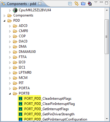
PDD in the Components View
Documentation
The Physical Device Driver manual is located under
CodeWarrior for Microcontrollers V10.x > Processor Expert Manuals > Processor Expert User Manual > Application Design

PDD Help
Ok, honestly, that documentation does not give much. It is very, very light, and maybe I have missed the extensive documentation somewhere? I did some trial-and-error, used the generated Processor Expert driver as examples, and I think I have found out how this works ![]() .
.
💡 The PDD ‘functions’ are not functions. They are C macros. Processor Expert is using them in the Kinetis drivers. I had a look how things are using in the BitIO_LDD component. Unfortunately PDD macros were not used everywhere, so this makes it hard to follow the code in the driver.
LED with PDD
In this tutorial, I’m using the red RGB LED on the FRDM-KL25Z board which is connected to pin 18 on PORTB (PTB18). In order to use it, I need to
- Clock the port module
- Configure the MUX (Multiplexer) to use it as GPIO (General Purpose I/O)
- Initialize the port value
- Configure the pin as output pin
💡 Technically, step 3 could be performed after step 4. But it is good practice to initialize the port value *before* driving the value to the pin. This avoids glitches or a sudden change on the output pin.
Header Files
First I need to include the header file for each PDD block. All PDD header files are located in
<CodeWarrior Installation Path>\MCU\ProcessorExpert\lib\Kinetis\pdd\inc\
To access the port pins, I need to include the PORT_PDD.h. Additionally I need access to the GPIO and SIM (System Integration Module):
#include "PORT_PDD.h" #include "GPIO_PDD.h" #include "SIM_PDD.h"💡 The best way to find out which header file to include is to have a look at the function name prefix. E.g. the functions in PORTB group show ‘PORT_PDD’, so this is what I need to include (PORT_PDD.h)
PORT_PDD Prefix in Function Names
Using PDD Macros
First, I need to clock the module with setting the clock gate. This is a setting of the SIM (System Integration Module):
SIM_PDD_SetClockGate Function
💡 I can drag&drop the methods to my source file, see this post.
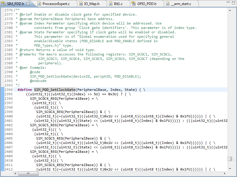
Pressing ‘F3’ (or context menu and then ‘Open Declaration’) shows me the definition of this macro:
SIM_PDD_SetClockGate Macro
As you can see, the macros are not simple :-(. But the doxygen comments for each macros give at least some hints. What I need to give is a base address, an index and a state. Here this is the SIM_BASE_PTR with the SIM_PDD_CLOCK_GATE_PORTB. And PDD_ENABLE enables the clock gate for it:
/* turn on clock to PORTB module: */ SIM_PDD_SetClockGate(SIM_BASE_PTR, SIM_PDD_CLOCK_GATE_PORTB, PDD_ENABLE);Next I need to set the pin muxing. The ALT1 function enables GPIO mode for the pin:
/* use ALT1 multiplexer mode so PTB18 is a GPIO pin: */ PORT_PDD_SetPinMuxControl(PORTB_BASE_PTR, 18, PORT_PDD_MUX_CONTROL_ALT1);Next, I initialize the value of the port pin:
/* init register output value (bit set): As LED is low active, the LED will be turned off */ GPIO_PDD_SetPortDataOutputMask(FPTB_BASE_PTR, (1<<18));Followed by setting the port as an output port:
/* Set port direction bit: configure PTB18 as output */ GPIO_PDD_SetPortDirection(FPTB_BASE_PTR, (1<<18));Now I can use the different GPIO_PDD macros to affect the output pin:
GPIO_PDD_ClearPortDataOutputMask(FPTB_BASE_PTR, (1<<18)); /* clear PTB17 bit: turn LED on */ GPIO_PDD_SetPortDataOutputMask(FPTB_BASE_PTR, (1<<18)); /* set PTB17 bit: turn LED off */ GPIO_PDD_TogglePortDataOutputMask(FPTB_BASE_PTR, (1<<18)); /* toggle PTB17 bit: LED will be on again */done 🙂
Source Code
And here is the complete code:
/* include PDD header files */ #include "PORT_PDD.h" #include "GPIO_PDD.h" #include "SIM_PDD.h" void RedLEDInit(void) { SIM_PDD_SetClockGate(SIM_BASE_PTR, SIM_PDD_CLOCK_GATE_PORTB, PDD_ENABLE); /* use ALT1 multiplexer mode so PTB18 is a GPIO pin: */ PORT_PDD_SetPinMuxControl(PORTB_BASE_PTR, 18, PORT_PDD_MUX_CONTROL_ALT1); /* init register output value (bit set): As LED is low active, the LED will be turned off */ GPIO_PDD_SetPortDataOutputMask(FPTB_BASE_PTR, (1<<18)); /* Set port direction bit: configure PTB18 as output */ GPIO_PDD_SetPortDirectionMask(FPTB_BASE_PTR, (1<<18)); } void RedLEDTest(void) { /* now play with the port value ... */ GPIO_PDD_ClearPortDataOutputMask(FPTB_BASE_PTR, (1<<18)); /* clear PTB18 bit: turn LED on */ GPIO_PDD_SetPortDataOutputMask(FPTB_BASE_PTR, (1<<18)); /* set PTB18 bit: turn LED off */ GPIO_PDD_TogglePortDataOutputMask(FPTB_BASE_PTR, (1<<18)); /* toggle PTB18 bit: LED will be on again */ }💡 The number ’18’ for PTB18 could be replaced with a macro.
Summary
PDD gives me direct access to low-level functionality on the microcontroller. And it helps me to directly access functionality of the device which is missing in the normal Processor Expert drivers, such as to use center-aligned PWM mode. While having PDD available is a good thing, it comes with limitations to consider:
- I only see it available for ARM devices, and not e.g. for my S08 or ColdFire projects. So it helps me for ARM, but not for my other projects I still have to support.
- Because of the low-level nature of the PDD, things are not likely portable between device families. So if I want to keep the software compatible for different micro controllers, I need to take special care.
The weakest part of the PDD is the documentation. I took me a long time and a lot of searching in the header files and generated driver code to find out what the proper macro usage is. But then, things worked out very well :-).
❓ If the doxygen comments in the header files of the PDD macros would actually tell me which arguments to use, that would be a big help. I had to do a lot of guessing and needed to play ‘human compiler and preprocessor’ to find out what works and what does not.
I need to explore PDD more, as the macros should help me either to remove some hard-coded initialization in my code, or making my drivers more efficient. So more work to do 😉
Happy PDDing 🙂


Thanks for a nice article!
I would just add a note that PDD macros are a good companion to Peripheral Initialization components (like Init_GPIO, Init_TPM etc..) that provide complete initialization code for a peripheral so the user can then just use PDD macros for runtime control of the peripheral.
In the Components view, the Peripheral Initialization components contain a PDD sub-folder with a list of macros only relevant for the selected peripheral.
LikeLike
Hi Petr,
yes, I have found out that PDD inside the Init component after writing that article, thanks for that hint!
LikeLike
Pingback: IoT: FreeRTOS Down to the Micro Amps | MCU on Eclipse
Pingback: Tutorial: Data Logger with the FRDM-K64F Board | MCU on Eclipse
Pingback: Tutorial: PWM with DMA on ARM/Kinetis | MCU on Eclipse
Pingback: Updated Freedom Board Logic Analyzer with DMA | MCU on Eclipse
Pingback: NeoShield: WS2812 RGB LED Shield with DMA and nRF24L01+ | MCU on Eclipse
Hi,
Did you use PDD also in Kinetis Design Studio? I cannot find it anywhere.
LikeLike
Yes, but they are not available for Kinetis SDK projects. Create a project with only Processor Expert (no Kinetis SDK).
LikeLike
Pingback: Overview: Processor Expert | MCU on Eclipse
Pingback: Porting Processor Expert Projects to MCUXpresso IDE | MCU on Eclipse
I think you should use GPIO_PDD_SetPortDirectionMask, since that macro doesn’t change ALL of the pin directions on the port at once.
GPIO_PDD_SetPortDirection Sets direction of every pin in the port.
LikeLike
Yes, that indeed is much better (I have updated the article).
Thanks!
LikeLike