
Question: How to build a low-cost logic open source logic analyzer for less than $15?
Answer: combine the Freedom KL25Z board with OLS!
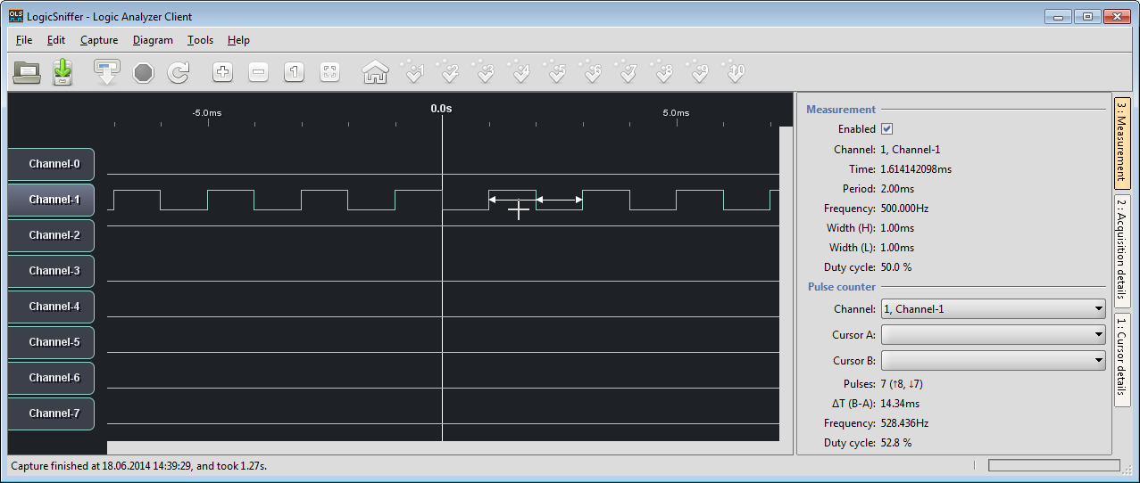
500 Hz signal with 50% duty cycle in LogicSniffer
I’m dealing recently a lot with DMA (see “Tutorial: PWM with DMA on ARM/Kinetis“), so I took the time to refactor the code to use DMA in a better way. In “Freedom Logic Analyzer with DMA” I needed to bridge PTD2 and PTD0, because this was routing the clock for the DMA trigger. Actually, this is not necessary and can be done directly from the timer/DMA :-).
The overall concept is this:
- AtimeronTPM0/Channel 1 (pinPTD1)isgeneratingaPWM signal (50% duty) which triggers a DMA transfer.Because PTD1 is as well the blue RGB LED, I can easily check the DMA transfer rate with another logic analyzer:
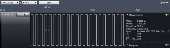
1 MHz DMA sampling frequency
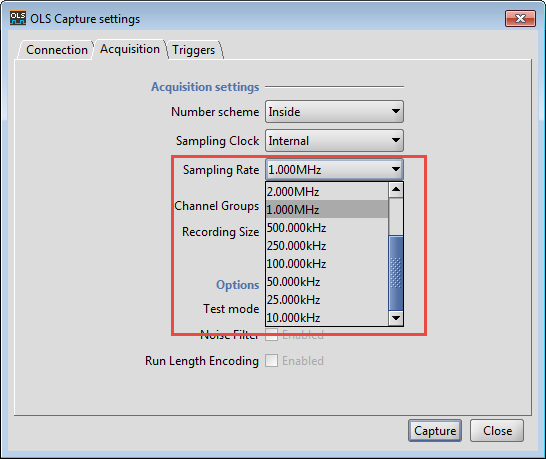
- The frequencyofTPM0/Channel1determinestheDMA sampling rateinOLS:
Sampling Rate in OLS
- In the application, I configure the DMA and adjust the sampling frequency as needed.
- The OLS/SUMP client does the rest: triggers and configuring the frequency, then transmitting the results to the client.

Components
To simplify the software, I’m using Processor Expert components. The Init_TPM component initializes my PWM which then will trigger the DMA:

TPM0 Configuration
With this, I have a base frequency of 48 MHz generating a PWM with a maximum frequency of 24 MHz, with DMA request enabled.
Inside the application, I’m using PDD macros to change the frequency:
static void TMR_SetTimerValue(uint32_t val) {
  TPM_PDD_WriteModuloReg(TPM0_BASE_PTR, val); /* set period of TPM0 */
  TPM_PDD_WriteChannelValueReg(TPM0_BASE_PTR, 1, val/2); /* channel 1: PWM low 50% */
}
And it gets initialized with 1 MHz period and DMA transfer enabled for DMA channel 1
static void TMR_Init(void) {
  TMR_SetTimerValue(LOG_TMR_FREQ/1000000); /* default of 1 MHz */
  TPM_PDD_EnableChannelDma(TPM0_BASE_PTR, 1); /* enable DMA for channel */
}
The DMA itself gets configured with source and destination addresses like this:
static void InitDMA(void) {
  /* enable DMA MUX0: */
  DMAMUX_PDD_EnableChannel(DMAMUX0_BASE_PTR, 0, PDD_ENABLE); /* enable DMA MUX0 */
  /* PIT triggering for DMA0: */
  DMAMUX_PDD_EnableTrigger(DMAMUX0_BASE_PTR, 0, PDD_DISABLE); /* disable PIT Trigger */
  /* use TPM0 overflow for DMA0 request: */
  DMAMUX_PDD_SetChannelSource(DMAMUX0_BASE_PTR, 0, 25); /* KL25Z reference manual, 3.4.8.1, p64: source number 25 TPM0 CH1 DMA source */

  /* DMA channel 0 source configuration: */
  DMA_PDD_SetSourceAddress(DMA_BASE_PTR, DMA_PDD_CHANNEL_0, (uint32_t)&GPIOC_PDIR); /* set source address */
  DMA_PDD_SetSourceAddressModulo(DMA_BASE_PTR, DMA_PDD_CHANNEL_0, DMA_PDD_CIRCULAR_BUFFER_DISABLED); /* no circular buffer */
  DMA_PDD_EnableSourceAddressIncrement(DMA_BASE_PTR, DMA_PDD_CHANNEL_0, PDD_DISABLE); /* source address will be incremented by transfer size */
  DMA_PDD_SetSourceDataTransferSize(DMA_BASE_PTR, DMA_PDD_CHANNEL_0, DMA_PDD_8_BIT); /* Transfer size from source  */

  /* DMA channel 0 destination configuration: */
  DMA_PDD_SetDestinationAddress(DMA_BASE_PTR, DMA_PDD_CHANNEL_0, (uint32_t)&sampleBuffer[0]); /* set destination address */
  DMA_PDD_SetDestinationAddressModulo(DMA_BASE_PTR, DMA_PDD_CHANNEL_0, DMA_PDD_CIRCULAR_BUFFER_DISABLED); /* no circular buffer */
  DMA_PDD_EnableDestinationAddressIncrement(DMA_BASE_PTR, DMA_PDD_CHANNEL_0, PDD_ENABLE); /* auto-increment for destination address */
  DMA_PDD_SetDestinationDataTransferSize(DMA_BASE_PTR, DMA_PDD_CHANNEL_0, DMA_PDD_8_BIT); /* Transfer to destination size */

  /* DMA channel 0 transfer configuration: */
  DMA_PDD_EnableTransferCompleteInterrupt(DMA_BASE_PTR, DMA_PDD_CHANNEL_0, PDD_ENABLE); /* request interrupt at the end of the DMA transfer */
  (void)DMA_PDD_GetRequestAutoDisableEnabled(DMA_BASE_PTR, DMA_PDD_CHANNEL_0); /* disable DMA request at the end of the sequence */
}
At the end of the DMA transfer (with the sample buffer full), it will raise an interrupt, where I set a flag:
void LOGIC_OnComplete(void) {
  finishedSampling = TRUE;
}
The last piece is to start the sampling of the signals, which is pretty simple: set the destination address and byte count to transfer, and then go:
static void TransferDMA(void) {
  DMA_PDD_SetDestinationAddress(DMA_BASE_PTR, DMA_PDD_CHANNEL_0, (uint32_t)&sampleBuffer[0]); /* set destination address */
  DMA_PDD_SetByteCount(DMA_BASE_PTR, DMA_PDD_CHANNEL_0, bufferSize); /* set number of bytes to transfer */
  DMA_PDD_EnablePeripheralRequest(DMA_BASE_PTR, DMA_PDD_CHANNEL_0, PDD_ENABLE); /* enable request from peripheral */
}
Everything else is kept as is, with some minor refactoring. The added benefit is that the number of source files is reduced, and everything is much cleaner now :-).
Summary
I have now an even better and simpler DMA solution for my low-cost logic analyzer, which works well up to 2 MHz sampling frequency. With 4 and up to 24 MHz the accuracy is not that good, still not clear what is causing this. Anyway, this is a low-cost analyzer, and 2 MHz is pretty decent for less than $15 :-). The only thing is that the KL25Z only has 16 KByte of RAM. I’m considering porting it to the FRDM-K64F which has 256 KByte RAM and a faster CPU.
The project has been updated on GitHub. The project has as well a S19 file so if you have a board, you simply can program the board with the OpenSDA bootloader.
Happy Sniffing 🙂

1. I’m very interested in seeing this ported to the K64F, so please add my vote. Bigger buffer is good.
2. From your work with OLS: Do you think it would be feasible to extend it to include mixed signal (analog and LA)?
LikeLike
Hi Dave,
1. vote noted :-). So far it is you and me 😉
2. Yes, this is possible with ols-v0.9.7 (I just got it running right now). I faced an issue with teh .cfg (configuration file). Somehow ols-v0.9.7 does not like CR-LF line endings. I have committed that new (working) .cfg file in the project on GitHub. To show an analog signal, I can sample it with 8bits, and transmit it like a digital/LA signal. But ols-v0.9.7 has mode where I can show the signal as an analog (8bit) signal :-). Pretty cool. For the K64F version I would have enough memory for 8 digital channels and say one 8bit analog channel. What do you think?
LikeLike
Hi Erich,
A cheap stand-alone mixed-mode hardware LA (based on FRDM-K64F or similar) would be very cool. For debugging embedded systems, a frequency range up to 10 KHz (0.1 msec) would be adequate for debugging many I/O signals. Perphas this would be slow enough to provide several (4?) analog channels.
But what I’d really need is a mixed-mode open-source dynamic debugger that interfaces to the target’s debug port (JTAG, et al) for monitoring variables as time-varying graphs. Think of something like FreeMaster, but with perhaps 32 channels of variables. Do you think OLS could form the foundation for a UI for something like this?
I wish that I could commision a software engineering group project at some university to create a debugger such as this. Ideally it would be a plugin to GDB/Eclipse.
If the dynamic debugger could also accept and correlate input from the FRDM-based mixed-mode LA, then this would be an absolutely fantastic tool for embedded software debug.
LikeLike
I will define next week the proposals for student semester work. I think I could make one work package for an open source mixed signal logic analyzer. As for accessing the debug port: yes, it would be possible to access e.g. memory through the SWD connection. I made some experiments in the past, but I have not completed the work (no time).
LikeLike
Hi Erich,
Please let me know if a live student project comes out of this. I’m very interested in an open source alternative to FreeMaster. Can you access my email address?
It would be good if symbols can be read from ELF/DWARF file. Perhaps there are some parts that could be drawn from the Open Source Debugger project.
Combining a dynamic graphical debugger with a mixed signal LA would be fantastic.
LikeLike
Would like to see a mixed mode LA based on the K64F too… Is there any way to send “live” data to OLS, this way not getting limited to the internal ram when needing longer capture time?
LikeLike
Right now I do not see a way to send ‘live’ data, but hey, it is all open source so can be changed 🙂
LikeLike
Hey Erich, really cool project.
Has anyone tried this on a OSX device successfully?
I am able to capture data, but sample count is always 2. I think this indicates something is wrong.
Any ideas?
Antonio
LikeLike
Fixed it – my bad – my waveform generator had a zero offset, when it should have been 1.65 V (3.3/2)
LikeLike
Hi Antonio,
cool, good that this has been resolved 🙂
Erich
LikeLike
So, with KL25 i have only one digital channel?
LikeLike
No, you can easily have 8. But up to you how you want to have it.
LikeLike
Pingback: Tutorial: Adafruit WS2812B NeoPixels with the Freescale FRDM-K64F Board – Part 5: DMA | MCU on Eclipse
I stumbled on this project by accident, but i have a few of the mbed capable boards including both the K64F and the KL25Z and i thought i’d see how the KL25Z worked as a logic analyser… im not sure if im doing something wrong, but to code the S19 file on the KL25Z, i hold down the reset button, plug it in, copy the .s19 file from the github repo to the “BOOTLOADER” drive that appears then just remove the cable right? dont need to safe eject or anything (although i have tried).
The board did have the latest opensda firmware on it, but no luck so far with the logicanalyser s19 file, just keeps booting straight into bootloader mode evertime (with or without the reset button pressed)… any hints what i might be doing wrong?
LikeLike
If you are in BOOTLOADER mode, then you are clearly in the wrong mode. In order to load the S19, you need to have the P&E OpenSDA firmware loaded. If you used mbed, then you have probably the wrong firmware on it (the CMSIS-DAP one). As for the P&E firmware, have for example a look here: https://mcuoneclipse.com/2013/12/14/new-pe-opensda-firmware-v114/
LikeLike
Ok i miss-interpretted i guess, i’ve was deliberately pushing it into bootloader mode originally because most of what i found said srec/s19 files had to be loaded that way… going back to the opensda firmware it did indeed load correctly
Thanks for that!
LikeLike
Pingback: How to Add Bluetooth Low Energy (BLE) Connection to ARM Cortex-M | MCU on Eclipse
You did a nice job on the logic analyzer. Is the source code still available? It doesn’t seem to be on Github, and I’d like to use it in my embedded systems classes since we use the FRDM-KL25Z.
Congrats on a very nice blog, BTW! Thanks for taking so much time to share your insights.
LikeLike
Hi Alex,
thanks 🙂
All the sources and project files are on GitHub here: https://github.com/ErichStyger/mcuoneclipse/tree/master/Examples/CodeWarrior/FRDM-KL25Z/Freedom_LogicAnalyzer
It is a CodeWarrior project, and I have only used the binary for a while. If you need a KDS project, let me know and I can look into porting it.
Erich
LikeLike
Thanks for the quick response! I’ll let you know if I end up doing anything interesting with it.
LikeLike
Please provide github link to the s19 file for this project, I have a frdm kl25z board I would like to use for an analyser
LikeLike
See the file on https://github.com/ErichStyger/mcuoneclipse/tree/master/Examples/CodeWarrior/FRDM-KL25Z/Freedom_LogicAnalyzer
LikeLike