For a project I need to change the PWM duty cycle after a PWM period is over. One way to do this is to have an interrupt at the end of the PWM period, and then set the new PWM duty (compare) register value in the interrupt. That works fine for ‘slow’ PWM frequencies, but if the PWM frequency is high, the CPU load is massively increasing. A better way is to use DMA (Direct Memory Access).
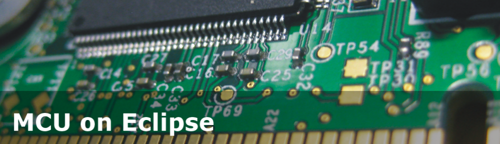
FRDM-KL25Z with DMA PWM and Logic Analyzer
DMA (Direct Memory Access) is present on many ARM microcontroller today, including the Kinetis family from Freescale. Each implementation has its own features. In general DMA allows a peripheral to use the memory directly without the need to use the microprocessor core register. This is great e.g. if a device needs to load/store chunks of memory. E.g. an AD (Analog Digital) converter can sample many channels, and then use DMA to store the results somewhere else in memory.
💡 See the links of application notes at the end of this article.
The DMA is like any other peripheral (SCI, USB, A/D, D/A, …), so it needs to be configured properly. As said above, DMA offers memory read/write/transfer operations. The following properties typically need to be configured (e.g. with registers):
- Request: who or what is triggering the operation
- Source: memory address where to read
- Destination: memory address where to write
- Transaction details: how many bytes to read, if source/destination address shall be changed after each transaction, if interrupts shall be generated, etc.
Outline
I’m using Processor Expert to have it easier to set up DMA, but of course you can use it directly or use it as guidance for your own (non-Processor Expert) project. I’m using the Freescale FRDM-KL25Z board, and using a PWM to toggle the blue RGB LED (PTD1) on that board. The goal is that the PWM duty cycle gets updated through DMA.
PWM Component
I add the Init_TPM component to my project to generate a PWM signal on pin PTD1 (my blue RGB LED):

Init_TPM component
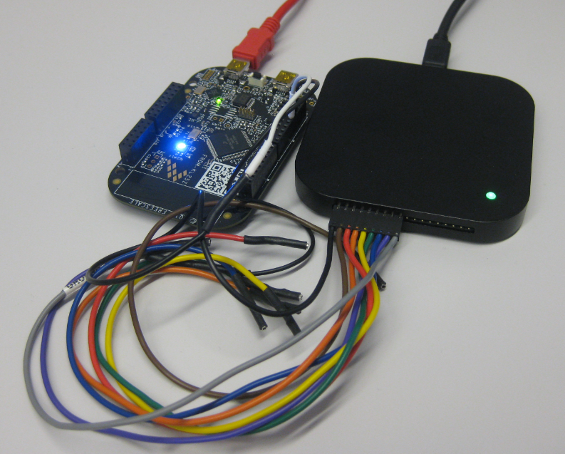
Then I configure it as follow:
- Using TPM0 because my pin PTD1 is muxed on that timer.
- My timer will overflow after 5000 ticks (modulo counter), which gives me a PWM period of 104 us (based on my bus clock).
- DMA request is enabled for the channel: when the PWM period ends, it will create a DMA request.
TPM0 PWM Configuration
Running this, I verify the result with the logic analyzer: a signal as expected :-):

50 Percent Duty Cycle
DMA Component
Next, I’m adding the DMAController_LDD to the project where I can configure the DMA channels. A depending DMAController component gets added automatically:

DMA Components
I do not need to configure anything inDMAController: everythingis handled in the DMA_Controller_LDD settings:

DMA Channel Configuration
- DMA request from TPM0_CH1_DMA_Request (this is Channel 1 from TPM0, my PWM configured above)
- Channel Using DMA_Channel0
- External object declaration: I can do source/destination address assignment at runtime (more about this below), but if I do it in the component, I need to provide a protoype so the compiler does not complain. I have here a declaration of my input buffer for the PWM/DMA request:
extern uint16_t dmaSrc[]; - As Source address I use the address of the first word of my source array, casted to 32bit address.
- Transaction size is 16bit (one entry of the array)
- Address Adjustment is zero, as I do not need any additional address adjustment after a transer.
- Address modulo I have configured to 32-bytes: that means that after 32-bytes (16 entries of my 2-byte array) it will wrap over. With this I have a ring buffer specified for my source data.
- In a similar way I configure the destination part. Only that I write to the TPM0_C1V (Timer Counter Value register).
- Enabled in initialization code makes sure that the driver is initialized, with Auto initialization enabled, so my application does not need to do this.
- I have enabled the ‘OnComplete‘ event: I will get an interrupt when all the transactions are done.
In the Transfer settings I keep the defaults: one request per transfer, with 2 bytes per request.
Using PDD
I have configured graphically many of the DMA settings above. It is possible to write the DMA register and settings by the application at runtime with PDD macros.
💡 See “Low-Level Coding with PDD (Physical Device Driver)” for details.
To set the destination address I can use
DMA_PDD_SetDestinationAddress(DMA_BASE_PTR, 0, (uint32_t)&TPM0_C1V); /* set destination address */The second parameter (zero) is the DMA channel number. To set the byte count to transfer I use
DMA_PDD_SetByteCount(DMA_BASE_PTR, 0, sizeof(dmaSrc)); /* set number of bytes to transfer */That byte count is very important: the DMA will transfer the data and decrement the byte count in the DMA register. Once the byte count is zero, the DMA stops. I have not found a way to have a ‘endless’ DMA means that it would automatically re-load the byte count at the end which would be a great feature (but again: not present on the KL25Z at least).
And this is used to ‘arm’ the DMA:
DMA_PDD_EnablePeripheralRequest(DMA_BASE_PTR, 0, PDD_ENABLE); /* enable request from peripheral */Application Software
I need to define my data to be used as duty cycle for the PWM:
#define BASE 200 /* used to scale the ticks */ uint16_t dmaSrc[]={ /* array used as source for DMA to set PWM duty */ 1*BASE, 2*BASE, 3*BASE, 4*BASE, 5*BASE, 6*BASE, 7*BASE, 8*BASE, 9*BASE, 10*BASE,11*BASE,12*BASE,13*BASE,14*BASE,15*BASE,16*BASE};Depending on your device used, you might need to align the buffer (see comments section). It can be done with using the __attribute__((aligned (<number>))):
uint16_t dmaSrc[]={ ... } __attribute__ ((aligned (16)));In the OnComplete() interrupt I need to set the byte count for the next transfer:
void DMACH1_OnComplete(LDD_TUserData *UserDataPtr) { DMA_PDD_SetByteCount(DMA_BASE_PTR, 0, sizeof(dmaSrc)); }All what I need to do in the application is to enable the request from the device (PWM) (e.g. in main()):
DMA_PDD_EnablePeripheralRequest(DMA_BASE_PTR, 0, PDD_ENABLE); /* enable request from peripheral */This gives 16 DMA PWM transfers:
16 DMA PWM cycles
I get 16 PWM cycles, then it calls DMACH1_OnComplete() where I set the byte count again, and so on. So compared with a ‘traditional’ approach to change the PWM cycle in the PWM interrupt, I have greatly reduced the interrupt load :-).
Below is a more extended code example, which configures the DMA in the application:
/* main.c */ #include "DMA1.h" #include "DMACH1.h" #include "TPM0.h" #define BASE 200 /* used to scale the ticks */ uint16_t dmaSrc[]={ /* array used as source for DMA to set PWM duty */ 1*BASE, 2*BASE, 3*BASE, 4*BASE, 5*BASE, 6*BASE, 7*BASE, 8*BASE, 9*BASE, 10*BASE,11*BASE,12*BASE,13*BASE,14*BASE,15*BASE,16*BASE}; void StartApp(void) { DMA_PDD_SetSourceAddress(DMA_BASE_PTR, DMA_PDD_CHANNEL_0, (uint32_t)&dmaSrc[0]); /* set destination address */ DMA_PDD_SetSourceAddressModulo(DMA_BASE_PTR, DMA_PDD_CHANNEL_0, DMA_PDD_CIRCULAR_BUFFER_32_BYTES); /* circular buffer with 32 bytes */ DMA_PDD_EnableSourceAddressIncrement(DMA_BASE_PTR, DMA_PDD_CHANNEL_0, PDD_ENABLE); /* source address will be incremented by transfer size */ DMA_PDD_SetSourceDataTransferSize(DMA_BASE_PTR, DMA_PDD_CHANNEL_0, DMA_PDD_16_BIT); /* Transfer from source size is 16bit */ DMA_PDD_SetDestinationAddress(DMA_BASE_PTR, DMA_PDD_CHANNEL_0, (uint32_t)&TPM0_C1V); /* set destination address */ DMA_PDD_SetDestinationAddressModulo(DMA_BASE_PTR, DMA_PDD_CHANNEL_0, DMA_PDD_CIRCULAR_BUFFER_DISABLED); /* no circular buffer */ DMA_PDD_EnableDestinationAddressIncrement(DMA_BASE_PTR, DMA_PDD_CHANNEL_0, PDD_DISABLE); /* no auto-increment for destination address */ DMA_PDD_SetDestinationDataTransferSize(DMA_BASE_PTR, DMA_PDD_CHANNEL_0, DMA_PDD_16_BIT); /* Transfer to destination size is 16bit */ DMA_PDD_SetByteCount(DMA_BASE_PTR, DMA_PDD_CHANNEL_0, sizeof(dmaSrc)); /* set number of bytes to transfer */ DMA_PDD_EnableTransferCompleteInterrupt(DMA_BASE_PTR, DMA_PDD_CHANNEL_0, PDD_ENABLE); /* request interrupt at the end of the DMA transfer to set new byte count */ DMA_PDD_EnablePeripheralRequest(DMA_BASE_PTR, DMA_PDD_CHANNEL_0, PDD_ENABLE); /* enable request from peripheral */ Cpu_EnableInt(); /* enable interrupts */ for(;;) { /* just wait here, DMA will do the work.... */ } } /* Events.c */ /* ** =================================================================== ** Event : DMACH1_OnComplete (module Events) ** ** Component : DMACH1 [DMAChannel_LDD] */ /*! ** @brief ** Called at the end of a DMA transfer. If the Half complete ** property in initialization section is enabled, this event is ** also called when current major iteration count reaches the ** halfway point. See SetEventMask() and GetEventMask() methods. ** @param ** UserDataPtr - Pointer to the user or ** RTOS specific data. This pointer is passed ** as the parameter of Init method. */ /* ===================================================================*/ void DMACH1_OnComplete(LDD_TUserData *UserDataPtr) { (void)UserDataPtr; DMA_PDD_SetByteCount(DMA_BASE_PTR, 0, sizeof(dmaSrc)); }Summary
With DMA I can do read/write operations in the background which leaves CPU cycles for my application. I recommend to approach DMA slowly, step by step, and I hope this tutorial helps.
Application Notes:

- AN4631: Using the Asynchronous DMA features of the Kinetis L Series
- AN4419: Using DMA and GPIO to emulate timer functionality on Kinetis Family Devices
Happy DMAing 🙂

Indeed it helps. I tried DMA for reading ADC with baremetal project of an old zilog controller, it gave me a headache, this approach looks easier with processor expert components, Thanks for the tutorial.
LikeLike
Erich,
To re-load the byte count at the end you can use DMA chaining. A second DMA channel can be chained to the first and be triggered when the first channel is completely done. After triggering, it can load the byte count again. I experimented with this on a KL05 and it worked fine.
–J.
LikeLike
Indeed, that would be another way instead of using the DMA interrupt, thanks for the tip!
LikeLike
Hello Erich and jwr
i’m trying to make a endless dma. I can reload the byte count of my first dma channel from a second DMA channel. But now i’m facing the problem that the byte count of my second DMA channel needs to be reloaded. How can i solve this probem?
Best regards
Dorian
LikeLike
Hi Dorian,
you could configure it for an ‘on DMA end’ interrupt, and then in that ‘end’ interrupt you would reload that value?
LikeLike
Hello Erich
thanks for your answer.
sorry, i didnt explain myself good enough.
If i’m using interrupts, there is no problem. I want to do the dma byte count reload without interrupts (so that the processor can sleep).
Basically i want to get 100 analog values (same channel, triggerd by pit) and then transferred by dma, without waking up the processor.
LikeLike
One solution i’m thinking of is to have the “DMA memory map” (x4000_8100 to x4000_813C) stored in a array, then the second dma channel would copy this array to the processor. When then the pit Interrupt comes, both DMA Channel would be ready, channel 1 to get the ADC data and channel 2 to reload the BCR Registers. Maybe that would do the job.
LikeLike
You could as well spend one DMA channel and have it as the last in a DMA chain: the job of the last DMA transfer would be to write the counter to the DMA register and trigger/start a new transfer.
It might depend as well on the DMA peripheral/version you are using, so there might be a bit/setting to have an ‘endless’ DMA?
LikeLike
Hello Erich
sometimes the solution is much easyer than it seens to be :). The approach to copy the “DMA memory map” didnt work, because the channel 2 overwrites its BCR Register at the end of the transfer.
The solution is much simpler. By simply setting the BCR (of channel 1) to a very big value, i’m able to perform several DMA transfers in a row, without the need to reload the BCR. And when the cpu wakes up, it can reload the BCR.
Thank you for your help and time.
Best regards
Dorian
LikeLike
If the ISR DMACH1_OnComplete is in the Events.c and the array dmaSrc is declared in the main.c, sizeof(dmaSrc) may cause an error “invalid application of ‘sizeof’ to incomplete type ‘uint16[]'”. I googled and find that sizeof() happens before extern. So the sizeof(dmaSrc) in Events.c can not be calculated before linking.
I declared an int in the main.c and extern the int in Events.c. Everything works find then.
LikeLike
Sorry for the misspelling in the last sentence. Everything works fine.
LikeLike
Yes, this is normal behaviour in C. In my code I call a function from the Events.c which has the prototype of the dmaSrc array. Another way would be to have the declaration in the header file. There are many ways.
LikeLike
Pingback: Updated Freedom Board Logic Analyzer with DMA | MCU on Eclipse
Pingback: First Adafruit NeoPixel Blinks with the FRDM Board | MCU on Eclipse
Pingback: LED Clock with Kitchen Hot Pan Protector | MCU on Eclipse
Hi Erich,
Can you tell me where can I download DMA_Controller component ?
LikeLike
It is part of the Processor Expert installation, at least for me?
LikeLike
I’m using version 10.5 and I have only these dma components:
DMA_LDD
DMACHANNEL_LDD
DMATransfer_LDD
LikeLike
I’m using 10.6. You can install 10.6 in parallel of 10.5 (so no need to uinstall 10.6). And the license file is the same for 10.5 and 10.6.
LikeLike
The processor expert components for DMA are DMA_LDD, DMAChannel_LDD, and DMATransfer_LDD as of kinetis design studio 1.1.1. Are these old components that will be changed when they upgrade kds?
LikeLike
Hi Erich,
I found DMA_CONTROLLER in Referenced Components added automatically by adding DMA_Channel.
Now, I set dma for uart0, but I have a problem that it stores bytes only in first element of destination array so DestinationAddress isn’t increasing (I think).
My settings are:
External object declaration: extern uint8_t dmaSrc[];
Source Transaction settings:
– start address: (uint21_t)&UART0_D
– transaction size: 8-bits
– Address adjustment: 0
– Address modulo: Buffer disabled
Source Transaction settings:
– start address: (uint32_t)&dmaSrc[0]
– transaction size: 8-bits
– Address adjustment: 0
– Address modulo: 16bytes
others I leaved as default.
I added UART0_DMA_init(void) function:
void StartDMA(void) {
UART0_DMA_init();
DMA_PDD_EnableDestinationAddressIncrement(DMA_BASE_PTR, DMA_PDD_CHANNEL_0, PDD_ENABLE); /* no auto-increment for destination address */
DMA_PDD_EnablePeripheralRequest(DMA_BASE_PTR, DMA_PDD_CHANNEL_0, PDD_ENABLE); /* enable request from peripheral */
for(;;) {
/* just wait here, DMA will do the work…. */
}
}
void UART0_DMA_init(void)
{
UART0_C2 &= ~(UART0_C2_TE_MASK | UART0_C2_RE_MASK);
UART0_C5 |= UART0_C5_RDMAE_MASK; // Turn on DMA request for UART0
UART0_C2 |= UART0_C2_RIE_MASK;
UART0_C2 |= (UART0_C2_TE_MASK | UART0_C2_RE_MASK);
}
Thanks .
LikeLike
I have tried DMA with uart by sending some characters. I get the characters on terminal. The below is my code. Now I need to receive the characters from uart when I type letters on terminal. Did u try that. If u tried and got the output please help me.
void StartApp(void) {
DMA_PDD_SetSourceAddress(DMA_BASE_PTR, DMA_PDD_CHANNEL_0, (uint32_t)&dmaSrc[0]); /* set destination address */
DMA_PDD_SetSourceAddressModulo(DMA_BASE_PTR, DMA_PDD_CHANNEL_0, DMA_PDD_CIRCULAR_BUFFER_16_BYTES); /* circular buffer with 32 bytes */
DMA_PDD_EnableSourceAddressIncrement(DMA_BASE_PTR, DMA_PDD_CHANNEL_0, PDD_ENABLE); /* source address will be incremented by transfer size */
DMA_PDD_SetSourceDataTransferSize(DMA_BASE_PTR, DMA_PDD_CHANNEL_0, DMA_PDD_8_BIT); /* Transfer from source size is 16bit */
DMA_PDD_SetDestinationAddress(DMA_BASE_PTR, DMA_PDD_CHANNEL_0, (uint32_t)&UART0_D); /* set destination address */
DMA_PDD_SetDestinationAddressModulo(DMA_BASE_PTR, DMA_PDD_CHANNEL_0, DMA_PDD_CIRCULAR_BUFFER_DISABLED); /* no circular buffer */
DMA_PDD_EnableDestinationAddressIncrement(DMA_BASE_PTR, DMA_PDD_CHANNEL_0, PDD_DISABLE); /* no auto-increment for destination address */
DMA_PDD_SetDestinationDataTransferSize(DMA_BASE_PTR, DMA_PDD_CHANNEL_0, DMA_PDD_8_BIT); /* Transfer to destination size is 16bit */
DMA_PDD_SetByteCount(DMA_BASE_PTR, DMA_PDD_CHANNEL_0, sizeof(dmaSrc)); /* set number of bytes to transfer */
DMA_PDD_EnableTransferCompleteInterrupt(DMA_BASE_PTR, DMA_PDD_CHANNEL_0, PDD_ENABLE); /* request interrupt at the end of the DMA transfer to set new byte count */
DMA_PDD_EnablePeripheralRequest(DMA_BASE_PTR, DMA_PDD_CHANNEL_0, PDD_ENABLE); /* enable request from peripheral */
Cpu_EnableInt(); /* enable interrupts */
for(;;) {
/* just wait here, DMA will do the work…. */
}
}
LikeLike
I have not used DMA with UART.
LikeLike
Hi Erich,
I solved destination address increment problem by setting
Destination Transaction settings:
– Address adjustment: 1
– Address modulo: Buffer disabled
But now I have a problem that I’m able to get bytes only once, could you know what’s going on ?
LikeLike
I appologize, I was not able to look at your earlier question, glad that this one got resolved. About that you get the byte only once: On Kinetis-L at least there is no ‘auto-repeat’, so there is no real continued re-transmission. I solved that in https://mcuoneclipse.com/2014/07/13/first-adafruit-neopixel-blinks-with-the-frdm-board/ and in https://mcuoneclipse.com/2014/07/18/adafruit-neopixel-clock-with-60-leds/ with using an ‘end of transmission’ interrupt so I know when the transfer is over, and then trigger again a new transfer.
LikeLike
Thank you very much, it worked.
Now, I have one more question:
Can I get bytes without setting byteCount ?
p.s. my transfer starts with \r\n and ends with \r\n
Thanks for your work.
LikeLike
No, it seems that I have to always write again that byte count, as it gets counted down by the DMA. I think I have not seen this in the documentation, but this is what I have found out in order to have it working.
LikeLike
if the question is that the DMA could check for the \r\n: then I think the answer is ‘no’: you need to provide a byte count.
LikeLike
I’m trying to get your example to work on TPM1CH0 on the KL26 freedom board. I can get the pwm to work using the Init_TPM bean, but can’t get the dma part to work using the dma beans or the PDD functions. The dma counter never counts down and never loads TPM1_C0V. I don’t see anywhere that tells the dma channel to listen for the timer channel, shouldn’t there be somewhere that says “ok dma channel 0, listen for a dma request from timer 1 channel 0”? I probably missed something in the datasheet.
LikeLike
Ah yes, should have read the DMAMUX chapter. Thought all the info I needed was in DMA chapter. I knew it was a datasheet comprehension problem!
LikeLike
Ah, yes, I had a similar problem dealing with it for weeks, and the problem was in the DMAMUX too. So you are not alone 😉
LikeLike
Is it possible to do this type of transfer using a bigger chip that has eDMA instead of DMA? I don’t see any reference to a cycle steal bit and am unable to cause eDMA to load anything into FTMx_CxV. I copied the bean output into readable code here freescale community thread/335531
LikeLike
I have not used eDMA yet (I only used DMA on the KL25Z). But yes, I think the same approach should be applicable for eDMA too. But it took me a lot of debugging and trial-and-error to get it done.
LikeLike
It took me an entire day to figure out eDMA to FTM! First, the FTM will not generate a channel event if CxV is zero as it will with the TPM. Second, the FTM will not trigger DMA unless the DMA bit AND the channel interrupt bits are both set, it will not generate an interrupt if the DMA bit is also set and it will not trigger DMA if only the DMA bit is set, go figure… So the main differences are between the FTM and the TPM, eDMA mostly worked as expected! The one eDMA gotcha I found is you have to clear DLASTSGA on init or the whole thing won’t work.
LikeLike
Yes, sounds like the usual problems I had as well for normal DMA. Without having a working (and good) example, it is very hard to find out what is going wrong….
LikeLike
Hi Erich,
First, congratulations on your website, it is great to have these tutorials to study.
I have a board with KL25Z equal to this tutorial. But I can not make this example work. I’ve tried several times, looked for other tutorials, information on datasheet but never worked.
The transfer occurs only when I use the startTransfer() function of the DMA component. However, I need that the ADC to make the transfer automatically.
Could you post the source-code, or RAR this project codewarrior? I wanted to test whether the problem is my freeboard.
If you can will help me a lot.
Again, congratulations on your work.
I’m sorry for English errors.
I’m Brazilian and I’m using google translator. kkkkk
LikeLike
Hello again Erich,
The tutorial worked !!! =)
I did not understand very well how the Request source work and that it was necessary to enable the request of the peripheral.
One question: the DMA_PDD_EnablePeripheralRequest function (DMA_BASE_PTR, 0, PDD_ENABLE) is equals StartTranfer() ???
Thanks!
LikeLike
Hi José,
glad to hear that things are working now :-). The DMA_PDD_EnablePeripheralRequest() sets that ‘enable’ bit in the DMA device, and will start a transfer.
Erich
LikeLike
hi i wanted to ask how i can use correctly the components DMA for read a signal from the ADC and then has write in the dac, is that is for read a signal in a range of 100hz a 100khz and display equal to the original signal, because i know that the dma help to the cpu , have you some example in procesor expert, where it use the dma for write in the dac the that it read of adc?
very thanks for the help.
LikeLike
Hi Cristian,
yes, this should be possible, but I don’t have exactly that example for you. And you can get help on Processor Expert component usage that way: https://mcuoneclipse.com/2012/11/12/getting-help-on-processor-expert-components/
LikeLike
Hi Erich
I forgot to thank for the tutorial, but try to test the example and not can make it to work because I get an error with the variable (uint32_t) &dmaSrc; [0]; It says ‘dmaSrc’ me (first use in this function) on the part of DMACH1.c and not is because the error generated
Could you post the source-code, or RAR this project codewarrior? .
thanks for the tutorial
LikeLike
Hi Christian,
all the needed sources are on GitHub. Have you created code with Processor Expert? Because all that code is generated and there is no need to have it as RAR or package on git.
LikeLike
hi erich
Thanks for helping me, is that I am back in “code warrior” because until one months ago was programming the mbed website.
LikeLike
Hello Erich,
Can You create in future one example with transfer data over SPI with DMA (on KL16 or KL26)? It would be very helpful for OLED display or external SPI Flash memory.
LikeLike
Yes, I had thought about using DMA on SPI, especially for SD cards.
LikeLike
Hello Erich,
First thanks for the help you provide on this blog. I learn pretty much everything about Processor Expert for Kinetis Board on this blog, I don’t know how else I would work.
Let me expose the system: I’m trying to use the internal ADC with DMA on Processor Expert to fill a table to calculate the average value of samples on four channels.
For the moment (without DMA), I successfully measure my variables and save them thanks to the help of your article https://mcuoneclipse.com/2013/02/10/tutorial-adc-with-the-freedom-board/.
However, the samplings are synchronized with a cycle interruption and only one sampling are done per cycle which lengths approximately 150µs. Due to this unique sampling per cycle, all the measured values are biased because they are always saved at the same “moment” of the cycle and really randomized.
Hence, I tried to use the DMA feature in the AdcLdd1 component to continuously measure my variables but it creates errors. It tells me that the “Result type” defined as “unsigned 16 bits, right justified” is “not supported with DMA enabled”. I’ve found that the interface required the GetMeasuredValues method but that one isn’t generated because disabled by component setting or by template.
So in the same component, it says that result type is not supported and useless and also at the same time required ? I’m sure there is only simple thing to do to solve the problem but I don’t find it….
Thanks in advance for your response.
Jérémy G.
LikeLike
Hi Jérémy,
thanks for you kind words 🙂
About ADC and DMA: I have not done that (yet?), but here is maybe something which can help you: DOC-96507
?
LikeLike
Hi Erich,
I finally found the solution few days ago after looking at many blogs and forum. The easiest way to implement ADC with DMA is by using the component ADC_LDD (orange icon) instead of the ADC – Legacy high level component (blue icon) you suggested in your tutorial about ADC. It allows the user to change the result type option to “signed/unsigned 16 bits, right justified” which is impossible with the legacy high level component because forces it to a different type.The other options are trivial, don’t forget the Auto Initialization.
The methods are a bit different to use, but it works fine with:
SelectSampleGroup(AD1_DeviceData, channelADC[0])
SetBuffer(AD1_DeviceData,adcValue,SIZE_BUFFER_DMA)
StartloopMeasurement(AD1_DeviceData)
The small problem on the KL25Z is that the hardware can only support static group with sample list of one element. If you want to change the ADC channel, you need to use SelectSampleGroup and SetBuffer again and change the pointer to adcValue + x*SIZE_BUFFER_DMA with x the number of the channel. All of this operation increases the cycle time.
I hope it can help some people.
Jérémy G.
LikeLike
Hi Jérémy,
thanks a lot for sharing how to get this done. I have not used DMA with ADC yet, so this is highly appreciated.
Erich
LikeLike
Hi Erich,
I’ve been using your blog to solve a lot of my issues while learning how to program a FRDM board. Thank you.
As I understand the reason to use DMA while trying to change the PWM Duty Cycle is to diminish the CPU load. I have a FRDM-KE06Z board and to my understanding it doesn’t have DMA. Do you have any other tricks to change the duty cycle (that is not with the traditional interrupts) in devices that don’t have DMA?
Thank you,
Leonardo
LikeLike
Hi Leonardo,
Glad to hear that my work here is useful for you :-), thank you!
About your question: the benefit of using DMA is that the peripheral (in this case the timer/PWM) can bypass the CPU and directly access/change things without a traditional ‘load-store’ through the CPU.
If you are not using interrupts, then you could directly write to the duty/match register of the timer, outside of an interrupt. However, this then will not be ‘synced’ with the current PWM cycle. Means depending on your hardware, when you write the modulo/match register of the timer, the PWM signal might change immediately. I have not checked the timers of the KE06, but it *could* be that the changed cycle will be in effect only when the current cycle is over (some timer implementation do this: they latch the new value and it only gets active in the next round of PWM cycle).
So it all depends on your requirements, and as well how fast your pwm frequency is: if it is slow (a few Hz), then you probably don’t need the interrupts. If it is faster (hundreds of Hz), then you should use interrupts. If higher, then DMA is needed. So if you really need this, then you should switch to a microcontroller which has the necessary capabilities.
I hope this helps,
Erich
LikeLiked by 1 person
Hi Erich, thank you so much for your help. I will delve into this issue as it seems that I’ll need to use pretty a fast PWM frequency. That means changing boards. This has helped me a lot. Thanks! Leonardo
LikeLike
Hi Erich,
I have a problem when I compile this program. The error is copied below. Please help on this how to remove this error. I want to learn how to use dma because I need to do write/read to an spi flash memory after this.
**** Build of configuration FLASH for project PWM_WITH_DMA ****
“C:\\Freescale\\CW MCU v10.7\\gnu\\bin\\mingw32-make” -j8 all
‘Building file: ../Sources/Events.c’
‘Executing target #1 ../Sources/Events.c’
‘Invoking: ARM Ltd Windows GCC C Compiler’
“C:/Freescale/CW MCU v10.7/Cross_Tools/arm-none-eabi-gcc-4_7_3/bin/arm-none-eabi-gcc” “../Sources/Events.c” @”Sources/Events.args” -MMD -MP -MF”Sources/Events.d” -o”Sources/Events.o”
‘Finished building: ../Sources/Events.c’
‘ ‘
‘Building target: PWM_WITH_DMA.elf’
‘Executing target #12 PWM_WITH_DMA.elf’
‘Invoking: ARM Ltd Windows GCC C Linker’
“C:/Freescale/CW MCU v10.7/Cross_Tools/arm-none-eabi-gcc-4_7_3/bin/arm-none-eabi-gcc” @”PWM_WITH_DMA.args” -o”PWM_WITH_DMA.elf”
./Generated_Code/DMACH1.o:(.data.dmaSrc+0x0): multiple definition of `dmaSrc’
./Generated_Code/Vectors.o:(.data.dmaSrc+0x0): first defined here
./Generated_Code/Cpu.o:(.data.dmaSrc+0x0): multiple definition of `dmaSrc’
./Generated_Code/Vectors.o:(.data.dmaSrc+0x0): first defined here
./Sources/main.o:(.data.dmaSrc+0x0): multiple definition of `dmaSrc’
./Generated_Code/Vectors.o:(.data.dmaSrc+0x0): first defined here
./Sources/Events.o:(.data.dmaSrc+0x0): multiple definition of `dmaSrc’
./Generated_Code/Vectors.o:(.data.dmaSrc+0x0): first defined here
collect2.exe: error: ld returned 1 exit status
mingw32-make: *** [PWM_WITH_DMA.elf] Error 1
LikeLike
Can you check that you have the ‘Generate ISRs’ option of the project set to ‘no’?

LikeLike
Hello,
I am using micro-controller MK10DN512VLQ10 .
Can I assign two DMA channels to single DMA source (slot) by using processor expert?
I want to assign DMA channel 8 and DMA channel 12 to ADC1 , DMA channel 10 and DMA channel 14 to ADC0.
Purpose is that DMA channel 8 would transfer ADC1 results directly to RAM buffer(ADC count would be used for DFT calculation).
DMA channel 12 would generate interrupt triggered by COCO (conversion complete) signal form ADC1 and at that interrupt ADC result would be copied to another separate buffer(ADC count would be used for transient detetcion).
Please let me know how a single DMA source (slot) can be associated with two DMA channels.
LikeLike
I don’t think this is supported in Processor Expert direclty. What you could use is the PDD (https://mcuoneclipse.com/2013/05/11/low-level-coding-with-pdd-physical-device-driver/)?
LikeLike
I’m debugging my implementation and realized that the circular buffer has to be aligned. My buffer is 4x 32b words, or 16 Bytes. But the linker didn’t align it, so when the DMA wraps the SAR back to the beginning of the buffer, it steps on some other RAM variables that happen to be located just before my buffer.
In MKL05 ref manual 23.3.4 DMA Control Register (DMA_DCRn), SMOD: “The base address should be aligned to a 0-modulo-(circular buffer size) boundary. Misaligned buffers are not possible. The boundary is forced to the value determined by the upper address bits in the field selection.”
So if my SMOD is set to 001 = Circular buffer size is 16 bytes, then the SAR beginning value should be aligned to 16bytes (i.e. the lower 4 bits of the address must be 0000)
How would do you align the circular buffer in RAM? Do I have to use a linker section, or some attribute?
Thanks!
LikeLike
Answering my own question: I found the answer in another of your wonder posts.
I defined my buffer like this and all is well:
static volatile uint32_t pwm_pit_times[4] __attribute__ ((aligned (16)));
I suggest adding this to your solution above just in case 🙂
LikeLiked by 1 person
Hi Paul,
I like that term ‘wonder posts’ :-). Thanks for providing that extra piece of information, I have added it now to the article for future readers.
Erich
LikeLike
Hello, I’m replicating your DMA operation. However, in the first step, I’m using a timer at 48MHz on the KL25Z, and I’m getting a period of 119us, 8.4kHz, which is significantly different from what I set, with a difference of 15us. I don’t have a good idea of how to solve this problem.
LikeLike
I rechecked and found a huge mistake of mine, that I shouldn’t rush to configure the timer directly, but should switch from the internal crystal to an external precision crystal to get an accurate enough core clock.
LikeLike
Not sure what could cause this. What timer source are you using? To get precise timing, you need a precise clock source. If using the internal clock source, it easily can be several % off because of temperature or not trimmed correctly.
LikeLike