
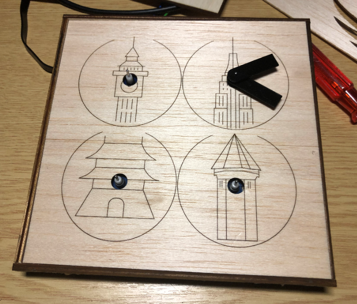
I really love clocks. I think this is I am living here in Switzerland. Beside of that: clock projects are just fun :-). After I have completed a single clock using stepper motors (see “DIY Stepper Motor Clock with NXP LPC845-BRK“), I wanted to build a special one which is able to show up to four different time zones: Below an example with London (UK), New York (USA), Beijing (China) and Lucerne (Switzerland):

Stepper Clock
The clock is not only able to show time for up to four different locations on the world: Using dual-shaft 360° stepper motors can show patterns beyond the time:
💡 In that video the minute hand is incrementing is changed every two seconds to advance the time faster.
In that project, a microcontroller (NXP LPC845, ARM Cortex-M0) is driving 8 stepper motors, one clock uses two motors, each individually controlled. Because the motors are special 360° motors, the zero position is determined with a magnet and a hall sensor for each hand. Using a serial connection, the clock can be configured. Because the clock can be away from a host PC, the clock uses RS-485.
Motors
This time the clock different concept than the one in “DIY Stepper Motor Clock with NXP LPC845-BRK“: instead of normal stepper motors it motors which are used behind the dashboard in cars. I evaluated different motors, and the VID28.12 dual shaft one was selected for this project. The motors have been tested first with a LPC845-BRK breakout board:
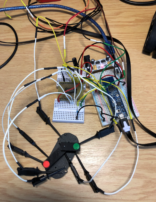
Testing the VID28.05 using NXP LPC845
Below a short video showing the motor in action:
Each VID28.12 unit includes two stepper motors with a dual shaft. The motor can be easily disassembled and modified as needed (e.g. for 360° operation):
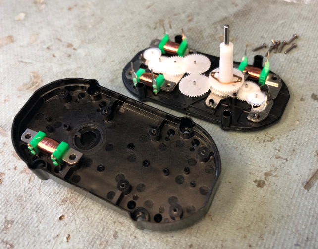
Disassembled VID28.05 Motor
For 360° operation, the end stop has to be removed (e.g. with a sharp knife). Otherwise the motor is available from the factory without the end stop (this is what I have ordered after the first test unit).

VID28.05 End-Stop
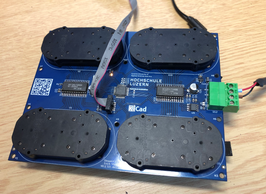
PCB
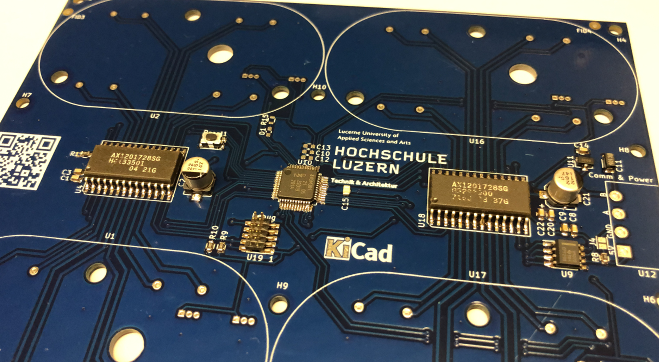
The PCB has been designed in KiCad:
- NXP LPC845 microcontroller
- 2 Switec X12.017 quad-stepper motor driver
- SWD debug port
- RS-485 interface
- 8 Hall sensors (AH3572)
- LED
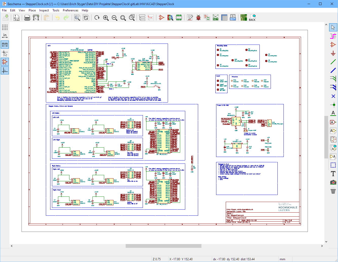
KiCad Project
The board has been produced by PCBWay. Below the first board which worked with a few patches.
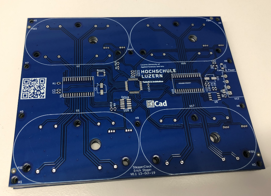
PCB V0.1 arrived
Reflow
The board only has a few parts on the bottom (clock front) side. Most components are 0603, with the microcontroller using 0.5 mm pitch the biggest challenge. Below the first board placed in the reflow oven:
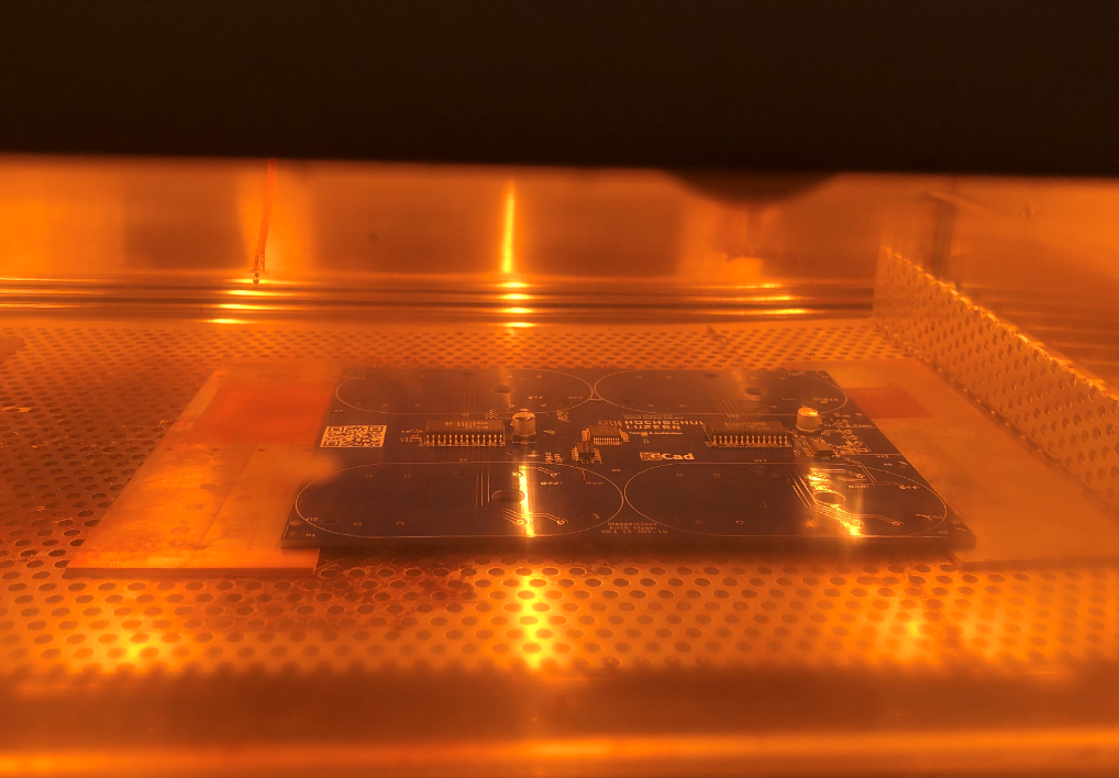
Board in Reflow Oven
It came out pretty good, with some excess solder (expected) on the microcontroller pins:
Out of the Reflow Oven
Issues
There are many ways to mess up things. As a list of reminders for myself (and maybe everyone else, nobody is perfect 😉 ):
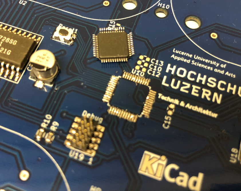
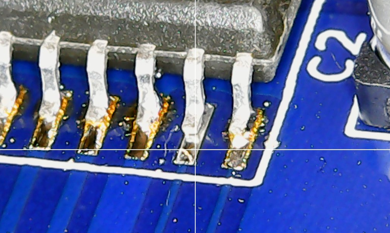
1) Carefully check the microcontroller pin alignment before getting it baked. It ended up soldered shifted by one pin.
💡 The image below shows excessive solder on the pinis which is on purpose and will be to be removed later.
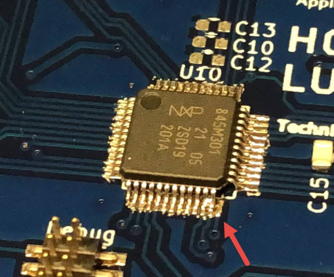
LPC shifted by one pin
Luckily I had an infrared heater available in the lab to get it off and on the board again:
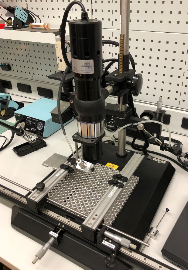
Infrared Heat System
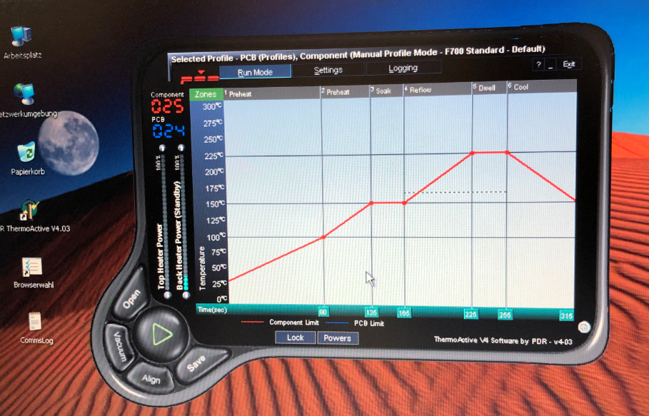
Selected Heat Profile
While the area (in red) is heated up, it gets monitored by a temperature sensor:

Heating it up
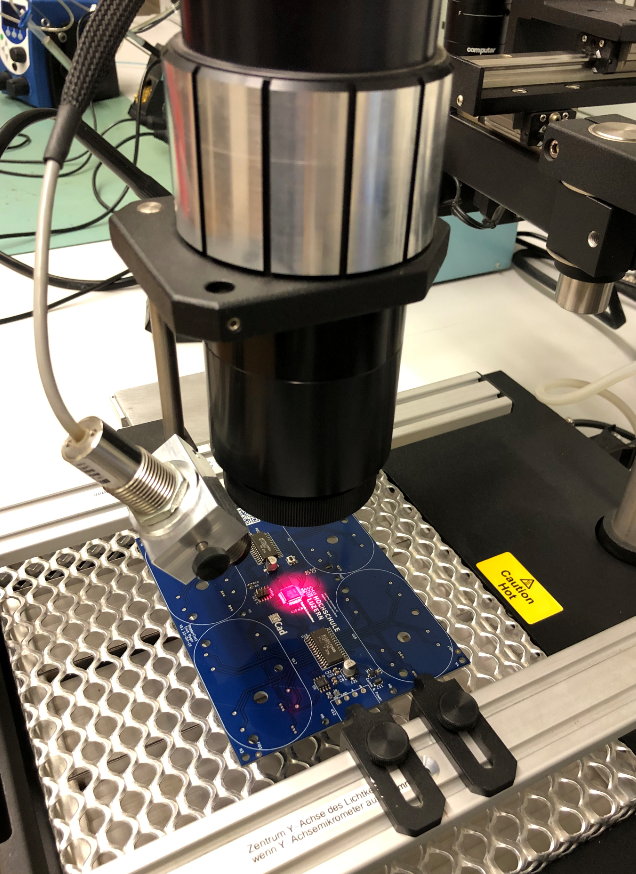
Heat on the focal point
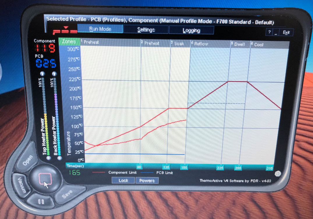
Running the Heat Profile
That way I was able to get it off the board easily:
Removed LPC Microcontroller
With the help of flux, solder wick, solder past and the heat gun the LPC was placed correctly the second time :-).
2) Don’t miss adding solder paste to a pad. Or don’t wonder why a motor is not able to change the direction:
Missing Solder Paste
3) There is no ‘standard’ footprint and pin numbering for SOT-23 packages. Carefully double-check the footprint and pin numbering used in the CAD tool. Or be prepared for painful board ‘fixes’. Luckily I had through-hole footprints added to the design as a backup.

Wrong Footprint
3) Carefully check marking and orientation of polarized capacitors. It is not a good idea to populate a tantalum capacitors reversed. It might ‘work’ for a week or so. But it will end with magic smoke:
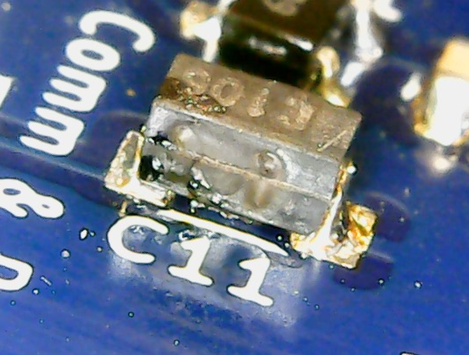
Tantalum capacitor blew up
First Test Runs
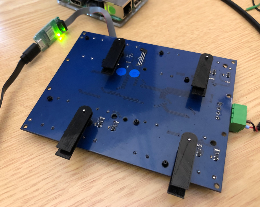
After populating the parts, it was time to develop the firmware. I added a SWD debug header on the board and used that to debug it with a SEGGER J-Link EDU Mini. The design includes RS-485 connector with 5V/GND so it can be powered from USB. I’m using a SparkFun USB-to-RS-485 converter board to connect it with the host PC to configure the board settings:
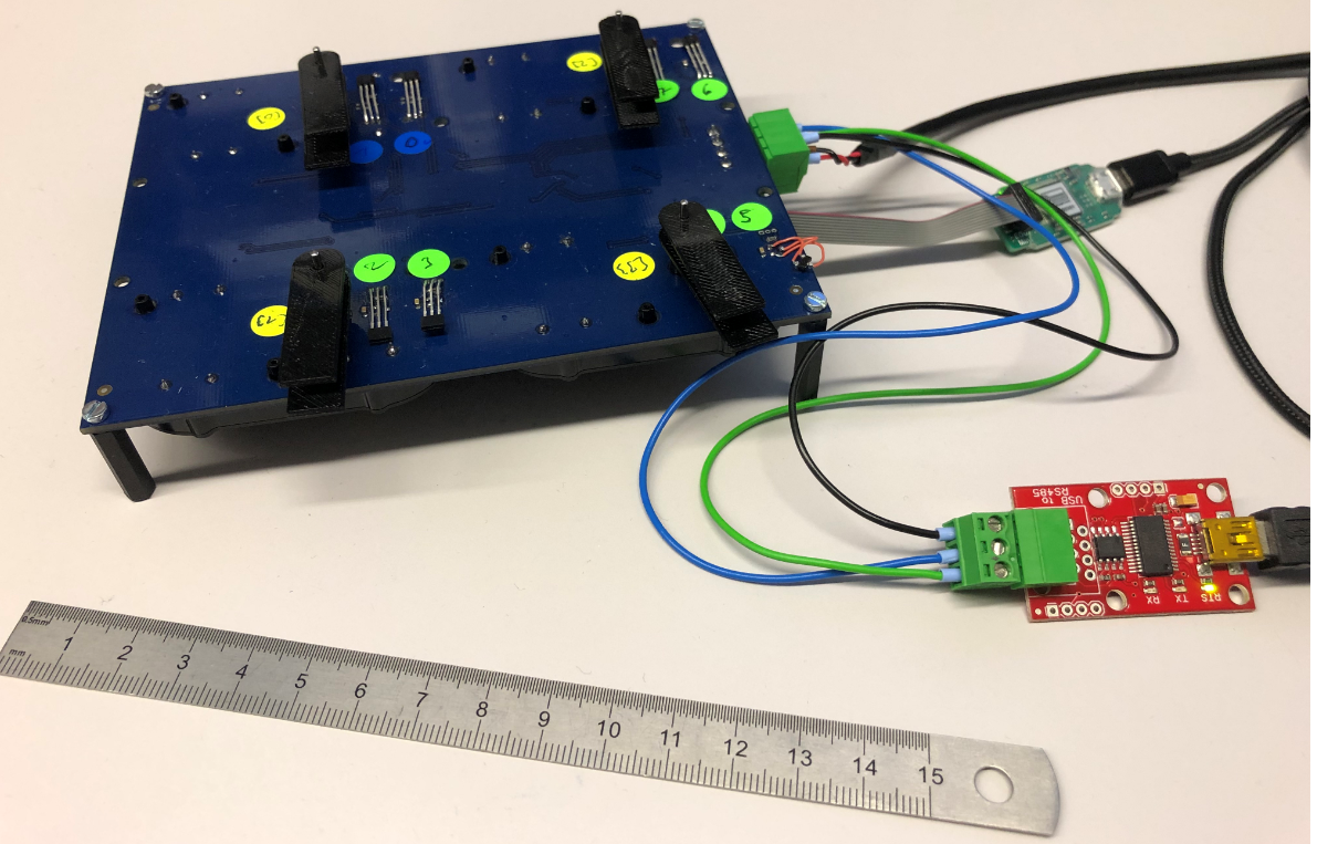
Board with RS-485
The first board assembled with motors and debug connector:
Board with motors
Below the front of the board with an initial set of clock hands:
Front of PCB with clock hands
The video below shows one of the early test with the motors:
Enclosure
The enclosure has been designed in Inkscape and then produced with a laser cutter. Below an first version. The sides and back are made of lasercut 4mm plywood. The front is using 1 mm balsa wood. That way everything is inside 17x17x2 cm.
StepperClock
The hands for the clocks are 3D printed with PLA and include special sockets for the magnets on the bottom side of each hand:
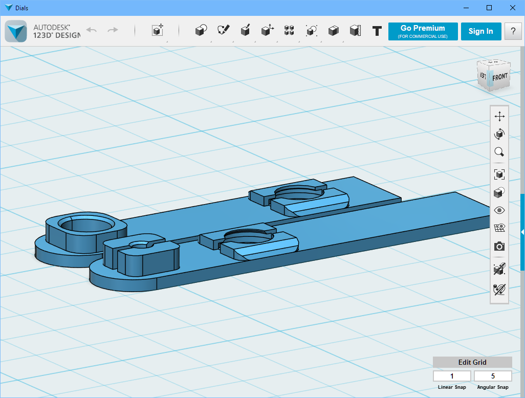
3D Hands
Firmware
The firmware has been developed with the NXP MCUXpresso IDE V11.0.1 using the NXP MCUXpresso SDK and the McuLib.
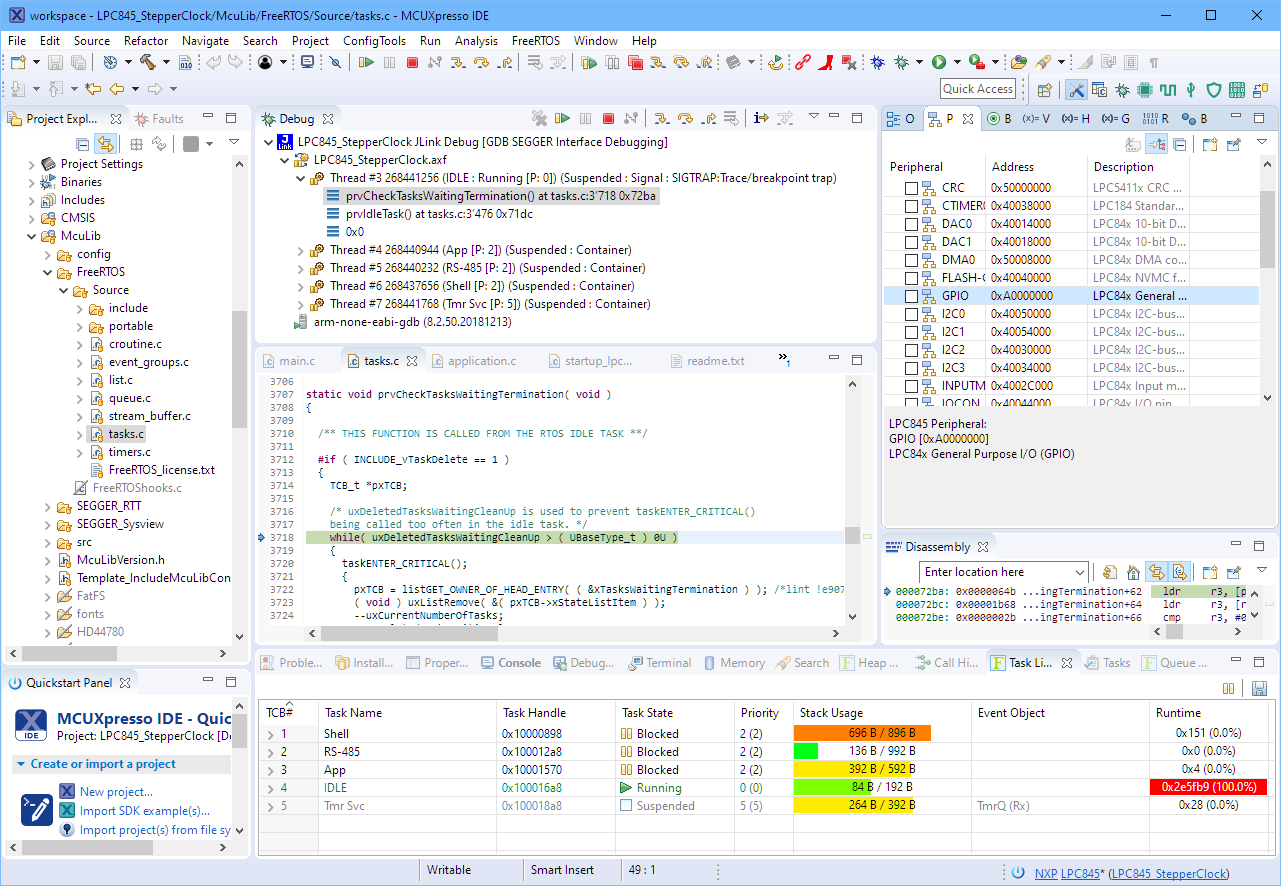
MCUXpresso IDE
The firmware includes a command line interface through the Segger RTT:
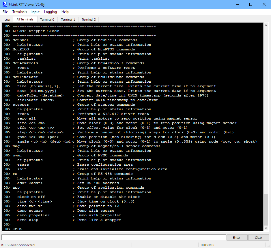
SEGGER RTT Command Line Interface
The same command line interface can be used over the RS-485 connection too. Configuration data like the clock hand offsets or RS-485 device address are stored in the microcontroller flash at runtime if reconfigured.
Summary
The result of the project is a versatile World Clock with four clocks make of automotive dashboard dual-shaft stepper motors. The clock is 17x17x2 cm in size and requires a 4-wire connection (5V, GND, A, B). It intentionally does not include a battery backed-up RTC (yet), as the idea is to connect multiple clocks to a bigger clock system. The clock can be used as a single clock, in that case it gets configured throught the RS-485 connection.
The design allows to use custom front covers, for example to show logos or landmarks for each time zone. For my first design I used London, New York, Beijing and Lucerne. The cover can be removed and replaced with a different one:
Stepper Clock
I plan to work on a new revision of the board. Until then, you can find the current firmware and design files on GitHub (see links below).
Happy TimeZoning 🙂
Links
- NXP MCUXpresso IDE V11.0.1
- McuOnEclipse Library: https://github.com/ErichStyger/McuOnEclipseLibrary
- LPC845-BRK: Unboxing the NXP LPC845-BRK Board
- Stepper Clock project on GitHub: https://github.com/ErichStyger/mcuoneclipse/tree/master/Examples/MCUXpresso/LPC845-BRK/LPC845-BRK_StepperClock
- SparkFun RS-485-to-USB converter: https://www.sparkfun.com/products/9822
- World-Clock project on GitHub: https://github.com/ErichStyger/mcuoneclipse/tree/master/Examples/MCUXpresso/LPC845-BRK/LPC845-WorldClock

Pingback: DIY ‘Meta Clock’ with 24 Analog Clocks | MCU on Eclipse
Pingback: Behind the Canvas: Making of “60 Billion Lights” | MCU on Eclipse
Hi Erich, a friend and I where very excited when we saw your multiple clock projects, especially the MetaClockClock projects. We were thinking of some magnificent clock to build and now we know what we want to build.
We searched a few weeks now for these stepper motors but could not find any offers online which seem to be okay to accept. Can you tell us where you get them? Directly from the Chinese supplier?
We would be honored to here from you with an answer.
Best regards,
Andre
LikeLike
Hi Andre,
good to hear that you like my projects :-).
Yes, I have the motors directly from the manufacturer in China (Peng Chung Electronics). You can find the motors from them if you search the following on AliExpress: BKA30D-R5 360 degrees
Let me know if this helps? And I would be honored to get updates on your project.
LikeLike
Hi Erich, wow thanks for the fast reply! 🙂
This helps us a lot, thank you! Currently we are in contact with a company which provides such clock works but with integrated reference detection. When we are lucky we can use their versions. But when not we can still fulfill our project with the ones from AliExpress. 😉
Can you tell us how noisy they are? My friend is concerned about the possible noise of 24+ motors changing there position every minute.
LikeLike
Can you share anything about that reference detection? I’m using external hall sensors which work but an internal sensor would be interesting too. About the noise: it is possible to hear the motors, but only in a silent room. you might check some of my videos which give you an impression. I know that there were many complaints about this motor type in other articles, but I feel they simply were using the motors in a wrong way (wrong wiring, wrong motor driver9 or not with micro-stepping. Unfortunately I don’t have the equipment to measure the sound, but the fan of my laptop generates more noise.
LikeLike
Hi Erich!
Really nice work and great results. I´m trying to build it as well and i just wonder weather you have the footprint of the BKA30d-R5 for KiCad. Would save me a lot of time (and wrong PCB´s maybe).
Thanks for sharing your project.
Greets from Germany
Sebastian
LikeLiked by 1 person
You can find the KiCAD files here: https://github.com/ErichStyger/mcuoneclipse/tree/master/KiCAD/Library
Greetings from Switzerland!
Erich
LikeLike
Great post thannk you
LikeLike
Thank you! Let me know if you build one of these clocks.
LikeLike