I really love tiny and bread board friendly boards, especially if they are very affordable and can be use with Eclipse based tools. So I was excited to see the NXP LPC845-BRK board to be available at Mouser, so I ended up ordering multiple boards right away. Why multiple? Because they only cost CHF 5.95 (around $6)!
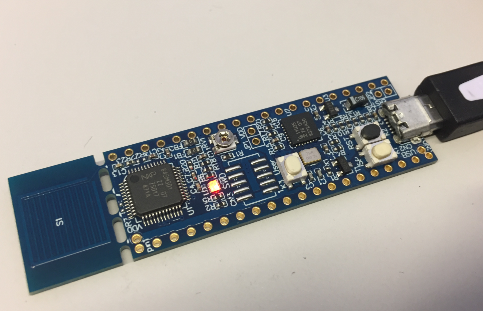
NXP LPC845-BRK Board
The boards arrived yesterday, so it is a perfect timing to have them (and more of it) integrated into the next semester university course material. So you will probably see a few more tutorials for this board.
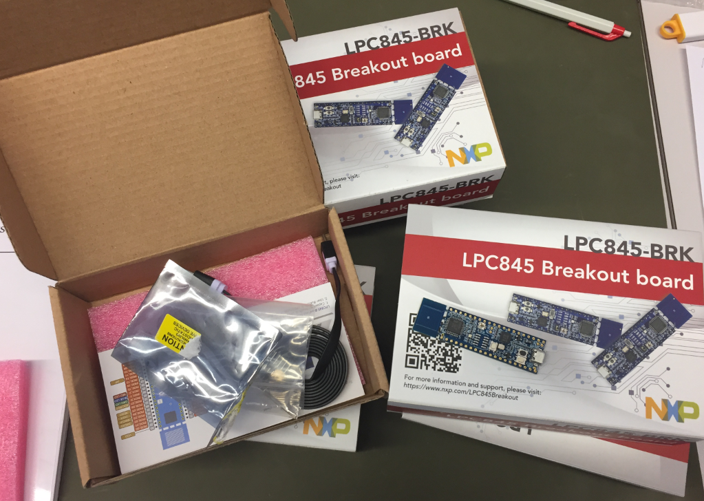
lpc845-brk boards
Unboxing
The kit comes in a solid card box with:
- the LPC845-BRK board
- two 10pin headers
- Micro USB cable
- a smalls screwdriver
- two 2pin jumpers and headers
- getting started reference card
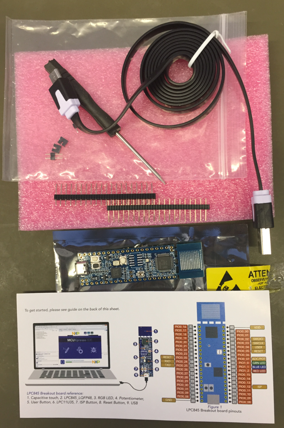
lpc845-brk kit content
The board works out of the box and does not need any soldering, and the headers are provided in case I want to customize the board. I like the fact that the headers are supplied, plus I’m free what I want to solder to the board. Plus I can use different headers if I want to. I was puzzled by the screwdriver (what for?) until I realized that there is small potentiometer on the board :-).
LPC845-BRK Board
The main MCU on the board is the LPC845 in QFN48 package ( LPC845M301JBD4), an ARM Cortex-M0+, 30 MHz, 64 KB FLASH and 16 KB SRAM):
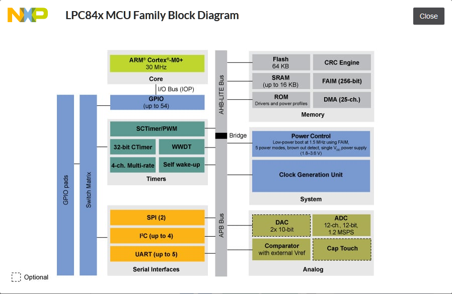
LPC84x Block Diagram (Source: NXP web site)
The board has a ‘break-apart’ touch area: if I don’t need it, I can make the board smaller. it includes a potentiometer, an RGB LED, three push buttons (Reset, user and ISP). Plus most important: the LPC11U35 acting as a debug probe:

LPC845-BRK Board Components
I can use the LPC845 with an external debug probe: for this I have to solder a jumper plus the 2×5 header. All the three buttons can be used as user buttons, so technically there are three of them. There is as well a jumper for an ammeter to measure the current used.
Software and Tools
There is no dedicated MCUXpresso SDK for that board (yet?), so I have downloaded the one for the device from http://mcuxpresso.nxp.com/:
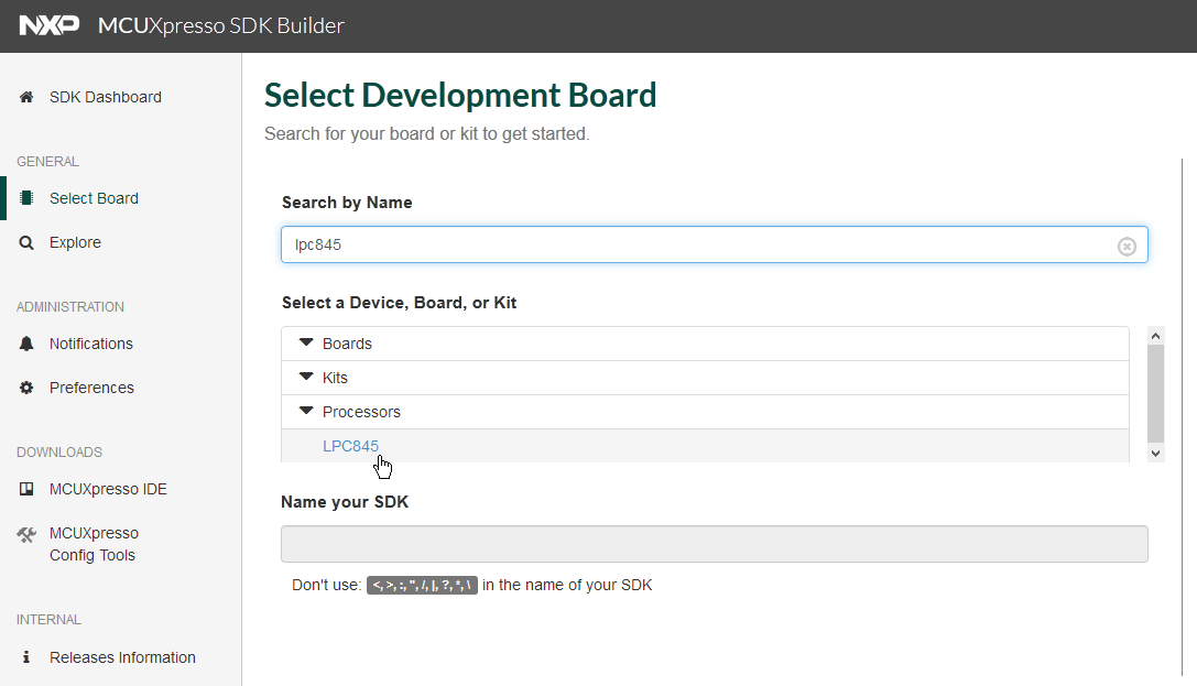
SDK for LPC845
With drag&drop I added it to the NXP MCUXpresso IDE 10.3.0:
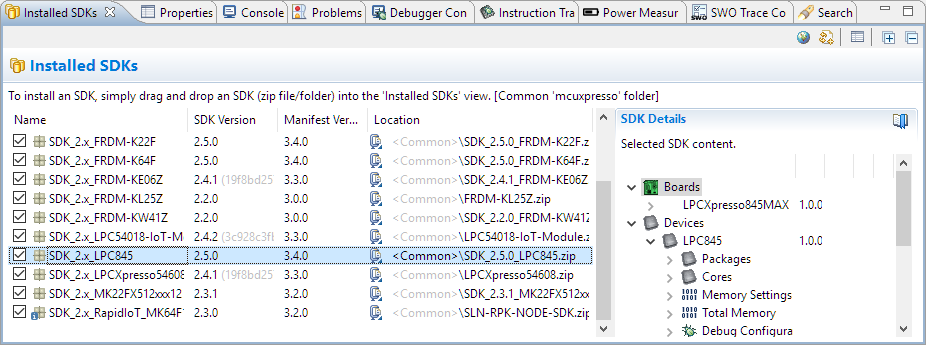
Installed SDK for LPC845
On the LPC845-BRK web site there is a zip file with examples which I have imported into the MCUXpresso IDE:
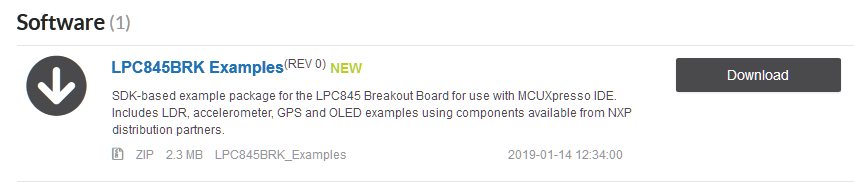
examples
When plugged in, the board enumerates with a virtual COM port which is a gateway to the LPC845 UART:
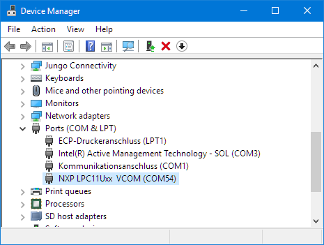
Virtual COM Port
I was able to debug the board out of the box, the board is recognized as CMSIS-DAP debug probe:
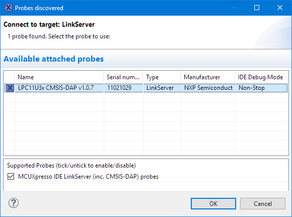
linkserver
And voilà: I’m debugging it 🙂
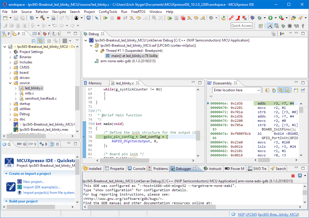
Debugging with MCUXpresso IDE
Summary
I really like that board. It is of good quality with a lot of value. It has a on-board debugger and even the possibility to use it directly with a J-Link or P&E Multilink if I wish so. The board is small, can be hooked on a bread board and can be made even smaller with removing the touch pad. The Cortex-M0+ is not the fastest and biggest MCU on the planet, but provides enough processing power for many smaller applications. I plan to follow-up with more tutorials in the next days and weeks. Until then, see the tutorials listed in the Links section below.
List of articles about the LPC845-BRK board:
- Unboxing the NXP LPC845-BRK Board
- Tutorial: Using external Debug Probes with NXP LPC845-BRK Board
- Tutorial: Transforming the NXP LPC845-BRK into a CMSIS-DAP Debug Probe
- Tutorial: Blinky with the NXP LPC845-BRK Board
Happy BRKing 🙂
Links
- LPC845-BRK Board web page: https://www.nxp.com/LPC845Breakout
- User Guide for LPC845-BRK Board: https://www.nxp.com/docs/en/user-guide/UM11181.pdf
- NXP LPC845 web page: https://www.nxp.com/products/processors-and-microcontrollers/arm-based-processors-and-mcus/lpc-cortex-m-mcus/lpc800-series-cortex-m0-plus-mcus/low-cost-microcontrollers-mcus-based-on-arm-cortex-m0-plus-cores:LPC84X?
- List of community projects: https://community.nxp.com/community/lpc/blog/2019/02/02/lpc845-brk-board-projects
- Light intensity measurement using the new LPC845 Breakout Board: https://community.nxp.com/community/lpc/blog/2019/01/14/light-intensity-measurement-using-the-new-lpc845
- Accelerometer controlled LED for LPC845 Breakout using SDK drivers: https://community.nxp.com/community/lpc/blog/2019/01/14/accelerometer-controlled-led-using-sdk-drivers
- Controlling LPC845 Breakout Board LED brightness using SDK Drivers: https://community.nxp.com/community/lpc/blog/2019/01/14/control-on-board-led-brightness-using-sdk-drivers
- LPC845 I2C Co-processor: https://www.hackster.io/ktown/lpc845-i2c-co-processor-698c43
- Wooden Tower Motion/Audio Sensor: https://www.hackster.io/ktown/wooden-tower-motion-audio-sensor-8b81b7
- MCUXpresso SDK: http://mcuxpresso.nxp.com/
- MCUXpresso IDE: New NXP MCUXpresso IDE V10.3.0 Release

‘not the fastest and biggest MCU on the plant’… wow! plants have MCUs today! 😉
LikeLiked by 1 person
Yes, they do! That is the way how I grow MCUs. It takes some time and watering, but the results are promising 🙂
LikeLike
Bio MCUs! 😉
LikeLike
And it solves the recycling problem too 😉
LikeLike
Thanks for the review Erich 🙂
There are a few nice projects for the board up on Hackster.io as well:
I2C co-processor for RPi: https://www.hackster.io/ktown/lpc845-i2c-co-processor-698c43
Jenga block motion detector: https://www.hackster.io/ktown/wooden-tower-motion-audio-sensor-8b81b7
LikeLiked by 1 person
Hi Brendon,
thanks, I have added these to the link list too now.
LikeLike
Erich, are you aware of this serious bug in GCC for M0/M0+, started from ver. 6 till the latest :
https://bugs.launchpad.net/gcc-arm-embedded/+bug/1803508
&
https://gcc.gnu.org/bugzilla/show_bug.cgi?id=88167 ?
Still not rectified…
LikeLike
Hi Jecek,
yes, I have seen that one, but luckily I’m not affected by this, as my code and FreeRTOS does not use the __builtin_return_address() compiler directive.
LikeLike
Pingback: Tutorial: Using external Debug Probes with NXP LPC845-BRK Board | MCU on Eclipse
Pingback: Tutorial: Transforming the NXP LPC845-BRK into a CMSIS-DAP Debug Probe | MCU on Eclipse
Pingback: Tutorial: Blinky with the NXP LPC845-BRK Board | MCU on Eclipse
Just one thing that I don’t like about these little boards is that there is a common resistor for the tri-colour LED, which means (at least for the part fitted to by boards) that only one can be lit at a time. I think they probably went just a little too far in keeping the cost down.
LikeLike
I saw that, but for me it was not an issue for me. And I think two extra resistors should not increase the costs much.
LikeLike
A single resistor was used for space reasons rather than cost… the resistor value have been lower to enable simultaneous use of all colors though… if the resistor value is reduced then all the LEDs do work. Need to get that value checked and posted…
LikeLike
Hi Branden,
thanks for that insight, appreciated.
Erich
LikeLike
Yes, that’s not really nice. But my biggest problem are the pin headers shipped with the board. I stupidly didn’t check them before carefully: They are too thin for my nearly allways used female Dupont jumper wires!
LikeLike
Actually I really love these thin headers: they plug in very easily into breadboards and do not damage them as other ‘bigger’ pins.
I wish I could find the supplier of these ‘thinner’ headers, maybe you know?
LikeLike
Pingback: Tutorial: RAK813 LoRaWAN+BLE+GPS Sensor Node with Eclipse IDE | MCU on Eclipse
Pingback: Tutorial: How to Optimize Code and RAM Size | MCU on Eclipse
Pingback: DIY Stepper Motor Clock with NXP LPC845-BRK | MCU on Eclipse
Pingback: World Stepper Clock with NXP LPC845 | MCU on Eclipse
Pingback: DIY ‘Meta Clock’ with 24 Analog Clocks | MCU on Eclipse
Pingback: Tutorial: Adding FreeRTOS to where there is no FreeRTOS | MCU on Eclipse
Pingback: Behind the Canvas: Making of “60 Billion Lights” | MCU on Eclipse
Pingback: New MCU-Link Debug Probe from NXP | MCU on Eclipse
Pingback: OpenOCD with MCU-Link | MCU on Eclipse
Pingback: Hey Google: Find ‘Error from StubMonSemihost: “monitor” command not supported by this target.’ | MCU on Eclipse
Pingback: “java.net.SocketException: Connection reset”: Check your Windows Updates! | MCU on Eclipse
Pingback: Doubling the performance of NXP LPC845 with improved Flash Access Time | MCU on Eclipse
Pingback: DIY Split-Flap Display | MCU on Eclipse