
The NXP LPC845-BRK board is a sub-$6 breadboard friendly development board with an ARM Cortex-M0+ on it. This tutorial is about developing a ‘blinky’ on it using MCUXpresso.

Binky on NXP LPC845-BRK Board
Outline
This tutorial goes through the tool installation and basics of implementing a blinky with MCUXpresso. It should give you a starting point to for your own application on that board.
💡 Note that this article uses a MCU (not board) SDK, because at the time writing this article only the MCU specific one was available. By now there is the LPC845BREAKOUT SDK available which supports the board and includes things like initialization of the LED pins.
Installation
For this tutorial we need:
- NXP LPC845-BRK board (see Unboxing the NXP LPC845-BRK Board)
- NXP MCUXpresso IDE (now V10.3.0, see New NXP MCUXpresso IDE V10.3.0 Release)
- NXP MCUXpresso SDK for the LPC845
Download the NXP MCUXpresso IDE from http://www.nxp.com/mcuxpresso/ide and install it with the default options.
Got to http://mcuxpresso.nxp.com/ and select the LPC845 SDK (there is no SDK for the board available yet). I recommend that you configure the SDK with all available software components.
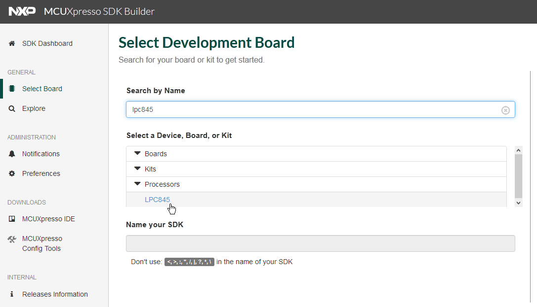
SDK for LPC845
Start the IDE (you can use the default workspace) and import the SDK (zip file) with drag&drop into the ‘Installed SDKs’ view:
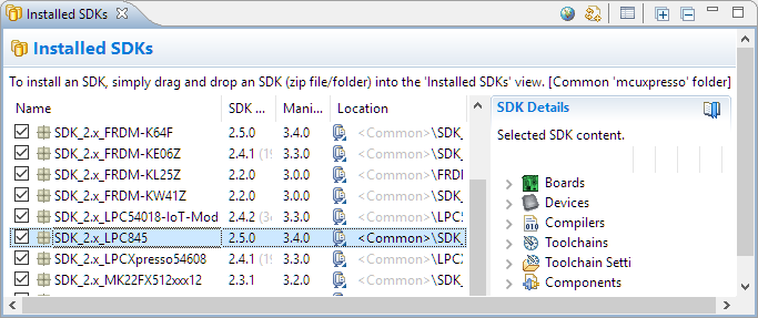
SDK for LPC845
New Project
Create a new project:
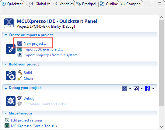
Create New Project
Select the LPC845 and press Next:
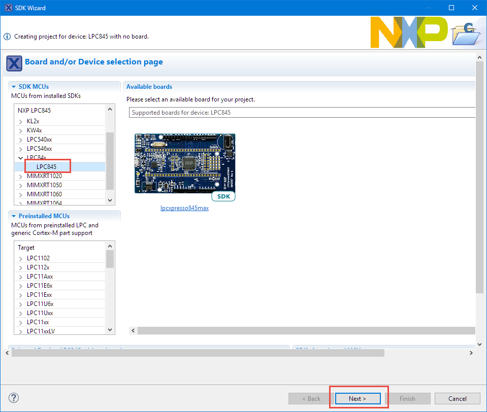
LPC845
Select the LPC845M301JBD48 for the Device package. Because we are going to use GPIO for the LEDs on the board, make sure that this driver is included. Then press Finish:
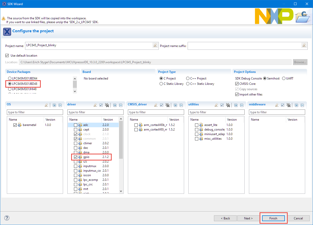
SDK Wizard
With this, we have a blinky project:
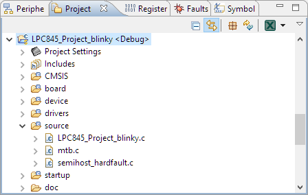
Blinky Project Created
LED Pins
Next we configure the pins for the LED on the board. From the schematics we get this information:
- Green on PIO1_0
- Blue on PIO1_1
- Red on PIO1_2
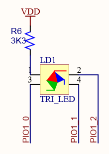
GPIO RGB LED Pins on LPC845-BRK
The pins need to be muxed as GPIO output pins. Select the project and open the Pins tool:
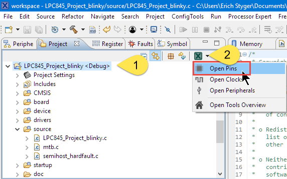
Open Pins Tool
Configure PIO1_0, PIO1_1 and PIO1_2 as GPIO pins. The easiest way is to double-click on the GPIO cell entries:
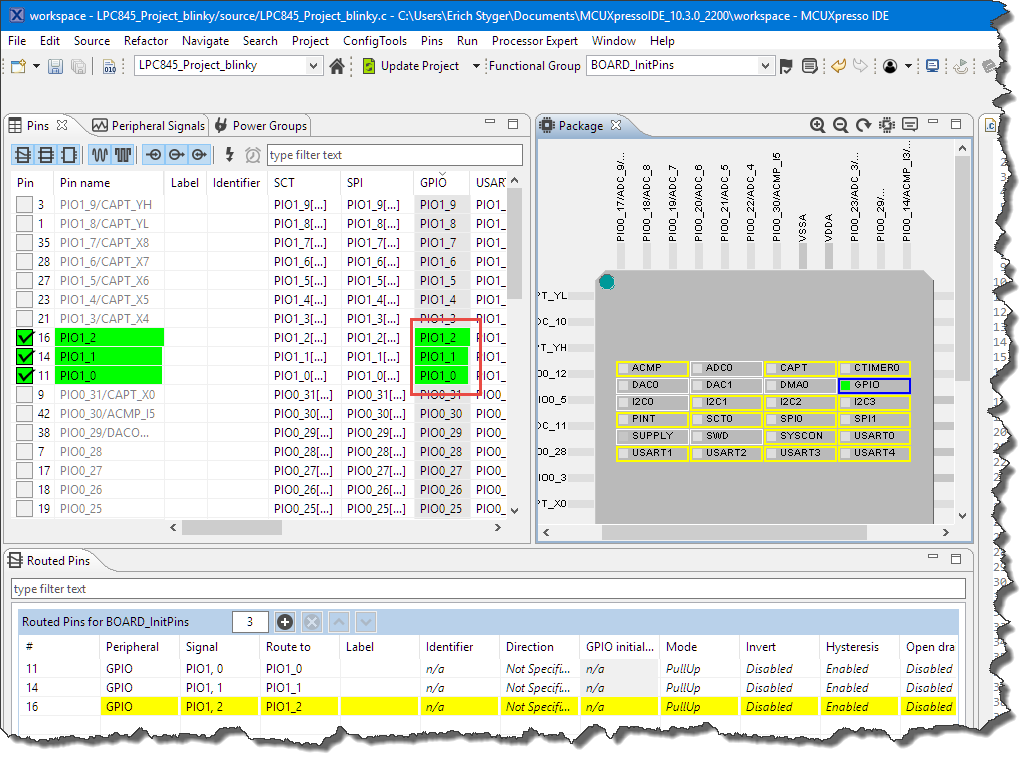
Configured LED GPIO Pins
Add Identifiers to the pins, for example LEDG, LEDB and LEDR. We will use #defines created for the pins later in our code:
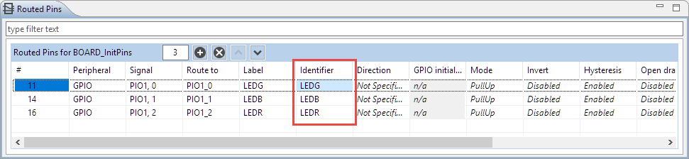
Identifiers for the Pins
That’s it. Update the project sources with our changes:
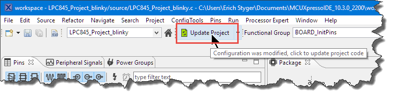
Update Project
It asks to confirm the changes. Press OK.

Updating Project
Switch back to the Develop Perspective (if not done automatically).
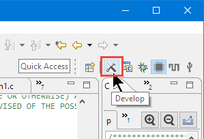
Develop Perspective
All the settings are stored in a .mex file. I can double-click on that file later to open the settings again:
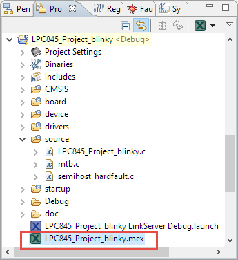
MEX File
Ungating Clocks
For the LEDs we are using the GPIO port 1 for which we have to ungate the clocks first, otherwise the GPIO pins won’t work.
Add the following to the includes:
#include "fsl_gpio.h"
Add the following line to ungate the clocks:
GPIO_PortInit(GPIO, 1); /* ungate the clocks for GPIO_1 */
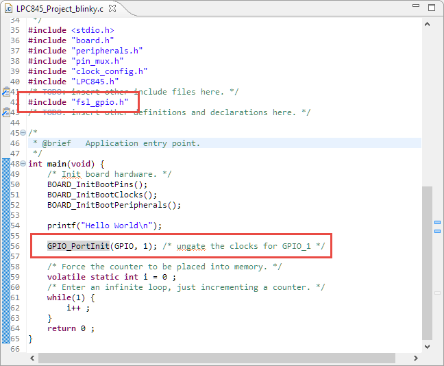
Ungating GPIO 1
Configuring GPIO Pins
Next we have to configure the GPIO pins as output pins with an initial HIGH (1) value. Add the following configuration to your code:
/* configuration for LOW active GPIO output pin */
static const gpio_pin_config_t configOutput = {
 kGPIO_DigitalOutput,  /* use as output pin */
 1,  /* initial value */
};
And initialize all the pins with that configuration:
/* initialize pins as output pins */
GPIO_PinInit(BOARD_INITPINS_LEDR_GPIO, BOARD_INITPINS_LEDR_PORT, BOARD_INITPINS_LEDR_PIN, &configOutput);
GPIO_PinInit(BOARD_INITPINS_LEDG_GPIO, BOARD_INITPINS_LEDG_PORT, BOARD_INITPINS_LEDG_PIN, &configOutput);
GPIO_PinInit(BOARD_INITPINS_LEDB_GPIO, BOARD_INITPINS_LEDB_PORT, BOARD_INITPINS_LEDB_PIN, &configOutput);
Notice that I’m using the Identifier (LEDG, LEDB and LEDR) in the macros I defined previously in the Pins tool.
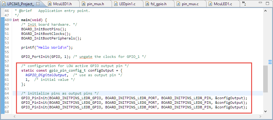
GPIO Init Pins
Delay
To slow down the LED blinky, add a delay function to the code:
static void delay(void) {
  for(int i=0;i<100000;i++) {
    __asm("nop");
  }
}
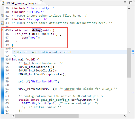
Delay
Blinky Code
Finally, add some blinky code to the application. The code below will turn on and off each led with a delay in between:
for(;;) { /* blinky, blinky, blinky! */
  /* red */
  GPIO_PortClear(BOARD_INITPINS_LEDR_GPIO, BOARD_INITPINS_LEDR_PORT, 1<<BOARD_INITPINS_LEDR_PIN); /* turn on */
  delay();
  GPIO_PortSet(BOARD_INITPINS_LEDR_GPIO, BOARD_INITPINS_LEDR_PORT, 1<<BOARD_INITPINS_LEDR_PIN);  /* turn off */

  /* green */
  GPIO_PortClear(BOARD_INITPINS_LEDG_GPIO, BOARD_INITPINS_LEDG_PORT, 1<<BOARD_INITPINS_LEDG_PIN); /* turn on */
  delay();
  GPIO_PortSet(BOARD_INITPINS_LEDG_GPIO, BOARD_INITPINS_LEDG_PORT, 1<<BOARD_INITPINS_LEDG_PIN);  /* turn off */

  /* blue */
  GPIO_PortClear(BOARD_INITPINS_LEDB_GPIO, BOARD_INITPINS_LEDB_PORT, 1<<BOARD_INITPINS_LEDB_PIN); /* turn on */
  delay();
  GPIO_PortSet(BOARD_INITPINS_LEDB_GPIO, BOARD_INITPINS_LEDB_PORT, 1<<BOARD_INITPINS_LEDB_PIN);  /* turn off */
}
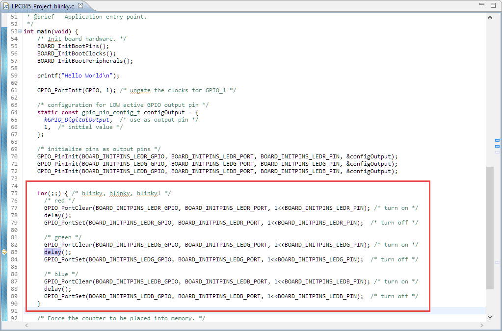
Blinky Code
Build and Debug
Time to build and then debug it with the board connected:
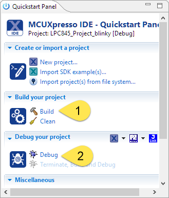
Build and Debug
With the board connected to the host, the IDE automatically recognized the board:
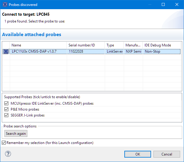
Probes discovered
Press OK and the debugger is loading the code:
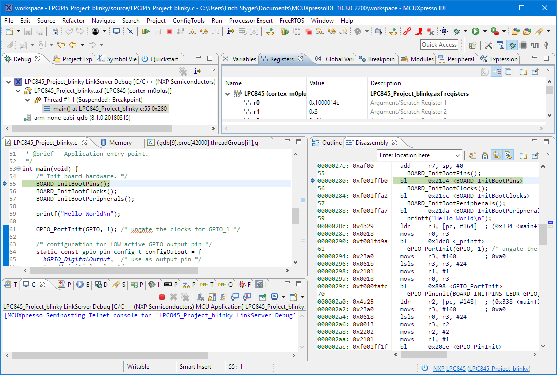
Debugging the Board
Run it, and enjoy the blinky-blinky-blinky 🙂
Binky on NXP LPC845-BRK Board
Summary
Although there is no dedicated SDK for the LPC845-BRK board yet, it is very simple and easy to create a blinky application for it. Using the NXP MCUXpresso SDK, IDE and Configuration tools it only needs a few lines in the application code to use the LEDs or any GPIO pins on the board.
List of articles about the LPC845-BRK board:
- Unboxing the NXP LPC845-BRK Board
- Tutorial: Using external Debug Probes with NXP LPC845-BRK Board
- Tutorial: Transforming the NXP LPC845-BRK into a CMSIS-DAP Debug Probe
- Tutorial: Blinky with the NXP LPC845-BRK Board
Happy Transforming 🙂
Links
- LPC845-BRK Board web page: https://www.nxp.com/LPC845Breakout
- User Guide for LPC845-BRK Board: https://www.nxp.com/docs/en/user-guide/UM11181.pdf
- NXP LPC845 web page: https://www.nxp.com/products/processors-and-microcontrollers/arm-based-processors-and-mcus/lpc-cortex-m-mcus/lpc800-series-cortex-m0-plus-mcus/low-cost-microcontrollers-mcus-based-on-arm-cortex-m0-plus-cores:LPC84X?
- MCUXpresso SDK: http://mcuxpresso.nxp.com/
- MCUXpresso IDE: http://www.nxp.com/mcuxpresso/ide
- MCUXpresso IDE 10.3.0: New NXP MCUXpresso IDE V10.3.0 Release
- List of community projects: https://community.nxp.com/community/lpc/blog/2019/02/02/lpc845-brk-board-projects

Pingback: Tutorial: Transforming the NXP LPC845-BRK into a CMSIS-DAP Debug Probe | MCU on Eclipse
Pingback: Tutorial: Using external Debug Probes with NXP LPC845-BRK Board | MCU on Eclipse
Pingback: Unboxing the NXP LPC845-BRK Board | MCU on Eclipse
Nice post, but I’m a little surprised that the generated code didn’t automatically ungate the clock on the GPIO port.
The Kinetis MCUs I have used have code in BOARD_InitPins() that does this without requiring the manual addition to the main() function. (the GPIO_PortInit() function just seems to call CLOCK_EnableClock() anyway).
e.g. on a Kinetis MCU….
void BOARD_InitPins(void)
{
/* Port A Clock Gate Control: Clock enabled */
CLOCK_EnableClock(kCLOCK_PortA);
….
LikeLike
Hi Phil,
yes, I was wondering too. I missed to add that ungating code initially and it took me a while to find out what was wrong. I’m not sure if I missed a setting or if things somewhow need to be different for LPC?
LikeLike
Pingback: Tutorial: How to Optimize Code and RAM Size | MCU on Eclipse
Pingback: DIY Stepper Motor Clock with NXP LPC845-BRK | MCU on Eclipse
Pingback: Doubling the performance of NXP LPC845 with improved Flash Access Time | MCU on Eclipse