
This project is about building a stepper motor clock around the NXP LPC845-BRK board. The design is using a combination of 3D printed and laser cut parts and costs below $15.

Stepper Clock Acrylic Face White Hands
Below a video of the clock in action:
Material and Tools
The GitHub repository (see links at the end of the article) includes an Excel file with the Bill-Of-Material (BOM). You need
- NXP MUCXpresso IDE (I have used the V11.0.0)
- NXP LPC845-BRK board
- 2 28BYJ-48 5V Stepper Motors with ULN2003 driver
- 2 Neodymium magnets (e.g. 5x2mm)
- Realtime clock with battery (DS3231)
- 2 Bearings 10x15x4mm
- 2 hall sensors (AH3572)
- Strand wires
- 12 M3 nuts and bolts
- 8 small (2×10 mm) wood
- Shrink-wrap tubing
- Soldering station and a few extra wires for power connection
- Plywood or PMMA/Acrylic material and access to a laser cutter
- Access to a 3D printer (I used an Ultimaker 2 with white PLA material)
- Optional: OpenSCAD to change the gears
- Optional: 3D modelling software to change the 3D models (I used 123Design from AutoDesc)
- Optional: wireless charging receiver module and charging station (see links at the end of the article for options)
Concept
The clock is designed around the very inexpensive 28BYJ-48 stepper motors (you can get 5 of them including the stepper motor driver board for less than $10).
The idea is to use the two stepper motors to driver each clock hand using a simple gear. the motors are placed in reverse to minimize space. The gears with shaft are 3D printed.

Stepper Motor Clock Concept
It is using the 28BYJ-48 5V stepper motors which come with a driver board with a ULN2003 on it:
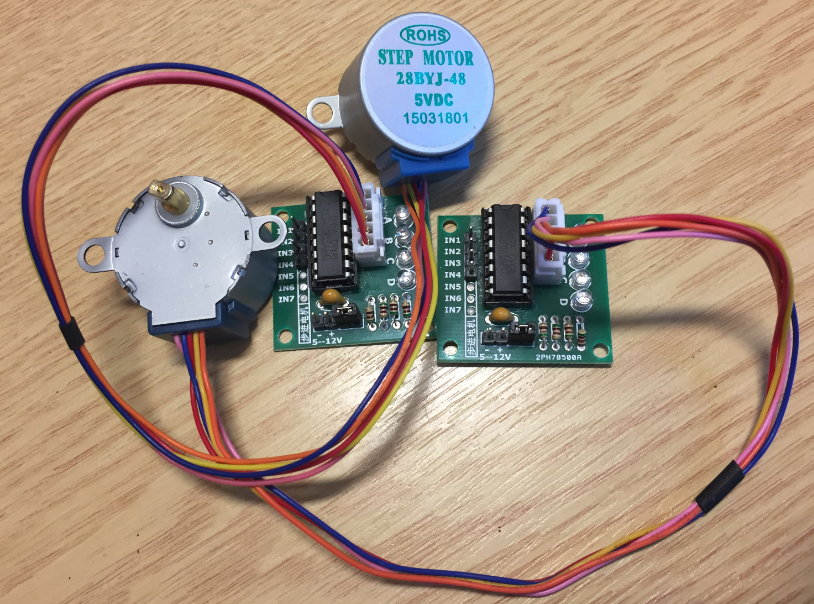
28BYJ-48 5V with ULN2003
Below shows an early prototype using the LPC845-BRK on a breadboard:

Stepper Clock Breadboard prototype
Gears
The gears are designed with OpenSCAD:
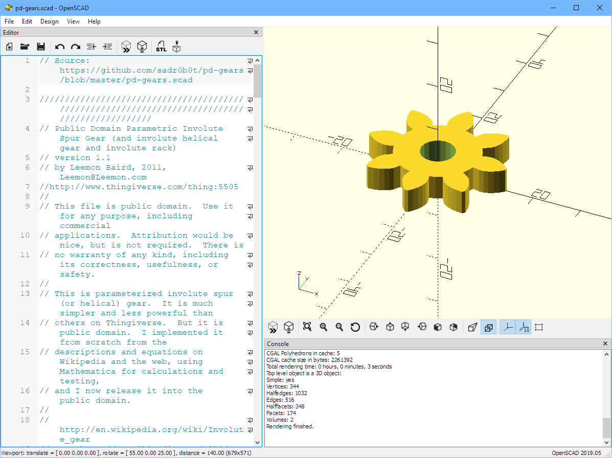
OpenSCAD
Using OpenSCAD the design can be parametrized and changed for a different gear factor.
3D printed parts
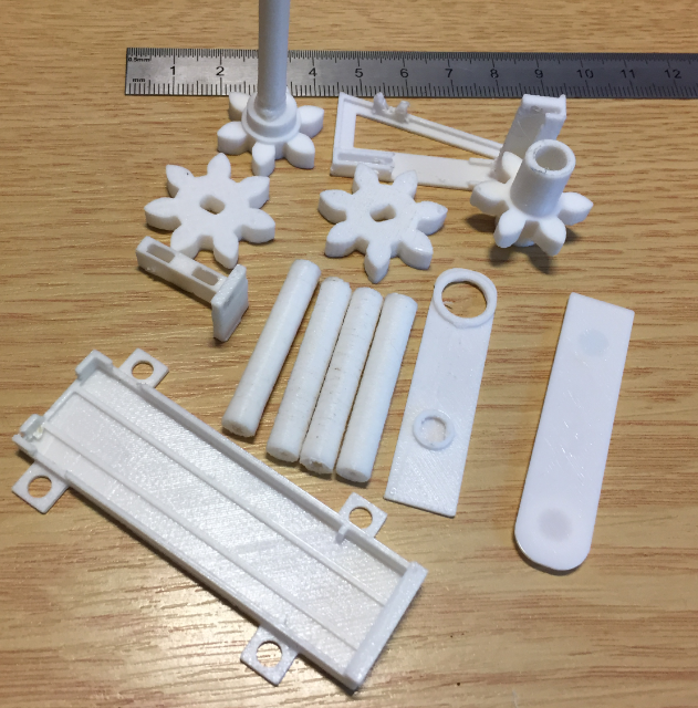
3D printed parts
The 3D files are available on GitHub as STL and 123D files:
- Minute inner shaft and gear
- Hour outer shaft and gear
- Minute and Second clock hand
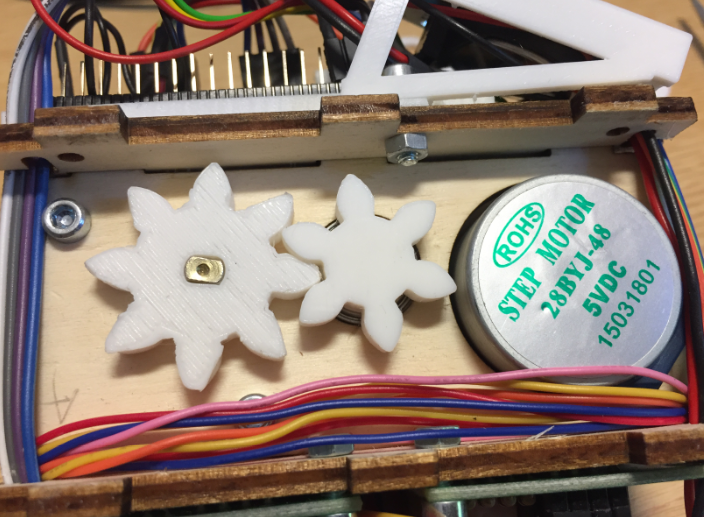
- 2 stepper motor gears
- RTC holder
- Hall sensor holder
- 4 spacer
- Microcontroller board holder
- Small spacer for inner hand gear
The spacer and gear parts should be printed with 100% infill.
To get a zero position, the design uses hall sensors to detect the hand zero position. For this magnets get pressed into both clock hands:
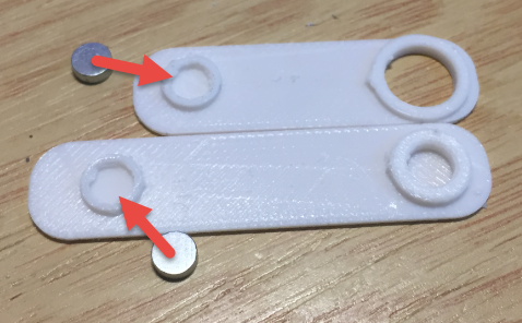
magnets in hands
Laser Cut Parts
The laser cut parts are designed with Inkscape (.svg):
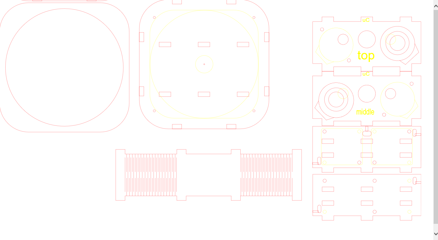
Laser Cut Parts
Optionally the parts could be 3D printed too, but this will take much longer. Different materials (plywood, PMMA/Acrylic) could be used, but usually plywood is the least expensive.
5V Motor Power Supply
Because the NXP LPC845-BRK does not expose the 5V on the pin rows, you can get to get it from pin 3 of U3 or from the positive side of C8
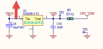
VBUS 5V (Source: LPC845-BRK Schematics)
Both locations are easily accessible, and I have used it from pin 3 Vin of the XC6206:
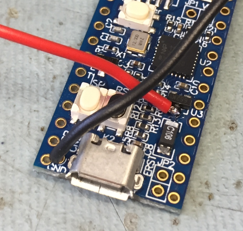
GND and 5V for Stepper Motors
Create two pin headers for each motor power supply:
5V Motor Power Supply
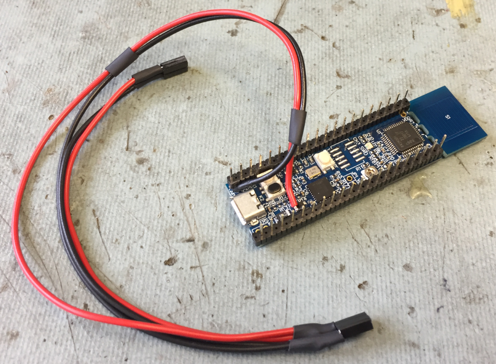
LPC845-BRK Pin Headers
The board comes with nice and breadboard friendly headers. Because the pins are thinner than normal ones, I recommend using ‘normal’ 2.54mm pin rows instead. Because the K1 switch is placed too close on to the pin row, cut them out so the row can fit on the top side:
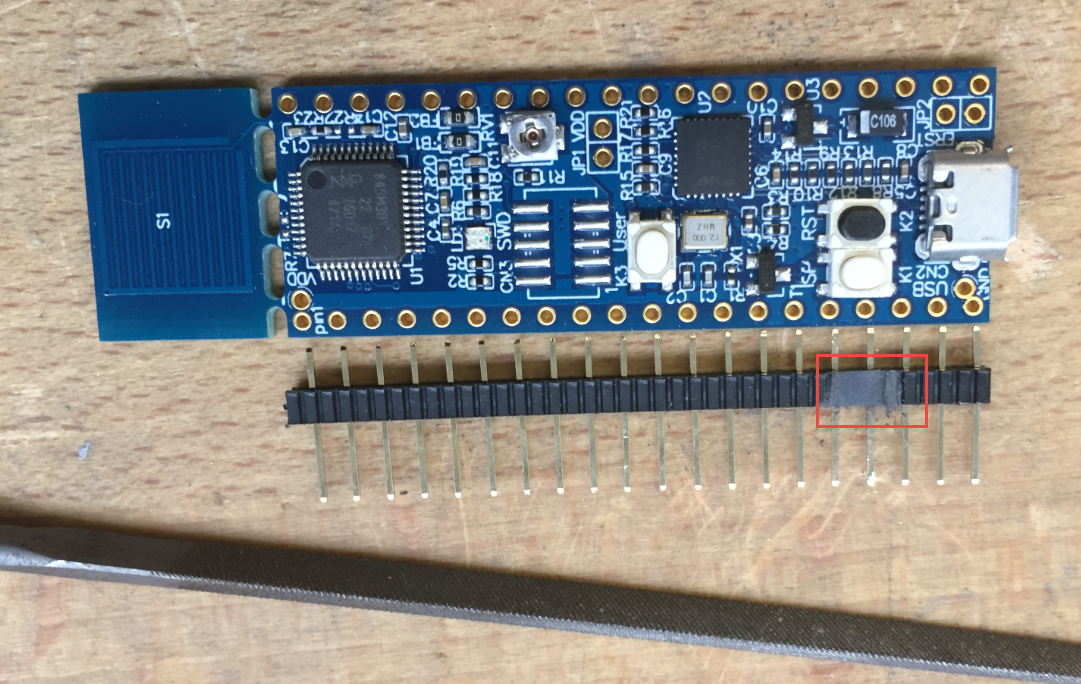
Pin Rows
Wiring
The wiring is pretty simple. If needed, different pins on the microcontroller board could be used (see next section).
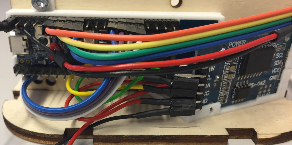
GND, magnet sensors and both motor connections are from the left side. Vdd/3.3v and the I2C for the RTC are from the right side:
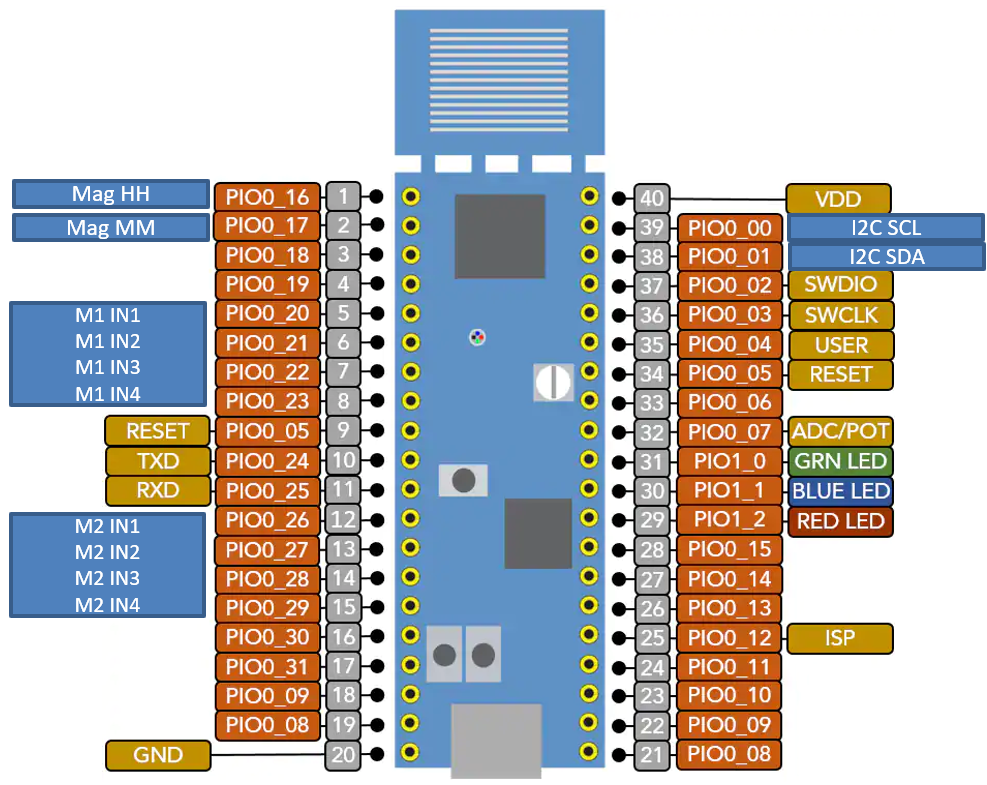
LPC845-BRK Stepper Clock Pins (adapted from NXP LPC845-BRK image)
Use shorter wires to connect to the DS3131 (RTC) module:
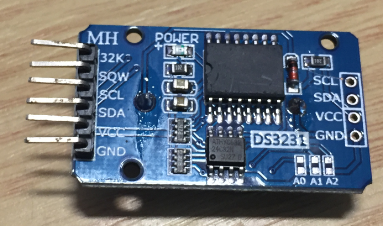
DS3131 Module
- black: GND
- red: 3.3V
- green: SCL
- yellow: SDA
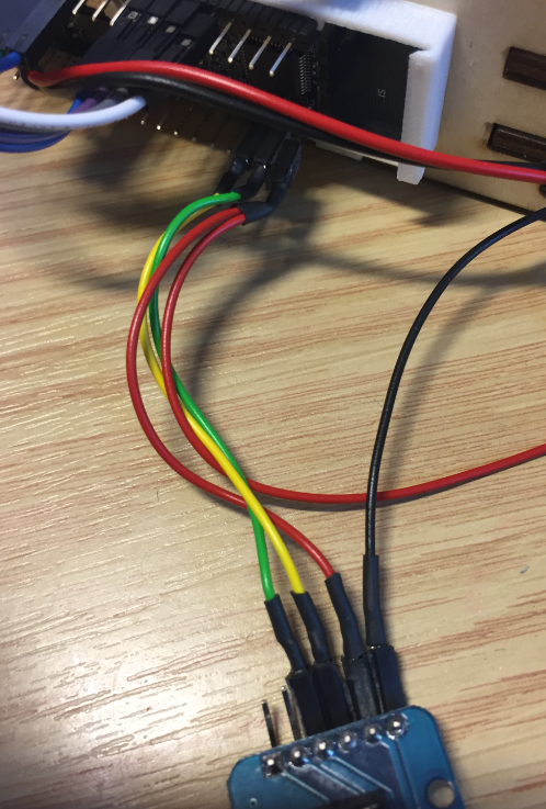
RTC wiring
Have the GND and 3.3V wires extended to the hall sensors, or use the extra pin connections on the RTC module. The module gets placed in its holder and attached with a screw below the microcontroller:
RTC Module in Holder
Solder the two hall sensor (GND, 3.3V and signal) to a cable, isolate with shrink tubing and put them into the holder as shown below:
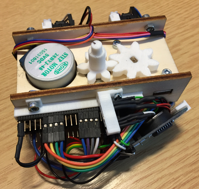
Assembled Clock Core
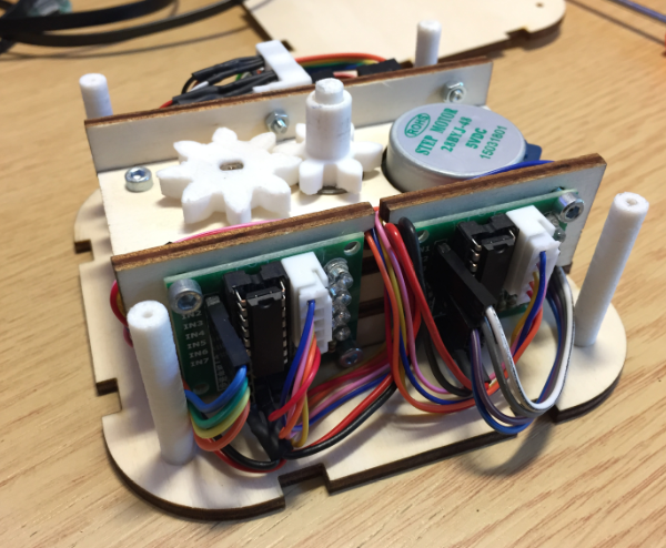
The two stepper motor driver boards get attached on the other side:
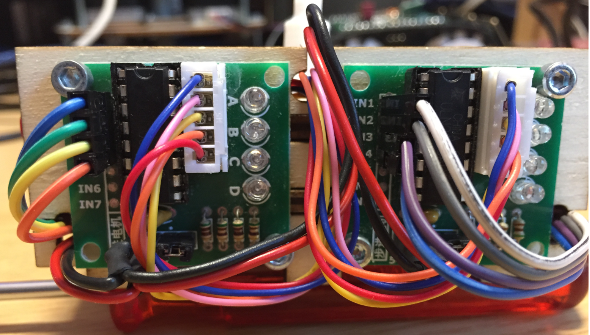
Motor Driver Side
Glue/place the small distance holder on the lowerw enclosure:
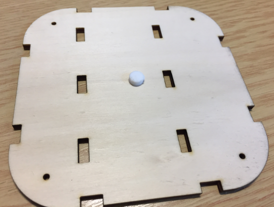
Inner Shaft distance holder
The bearings get placed in to the lower and top holder plates. The small plywood rings are glued to inside to prevent the bearings to fall inside.
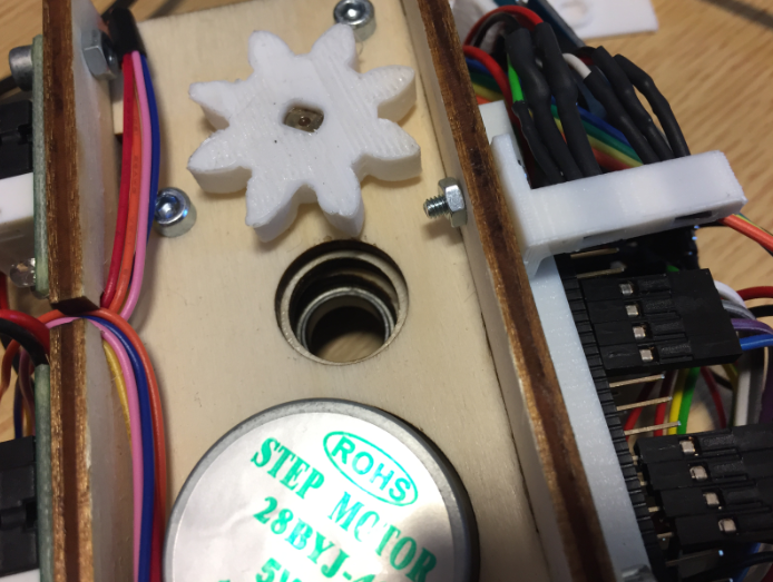
Space for Bearing
With the bearing inserted:
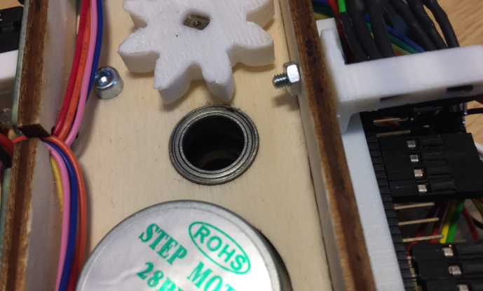
Inserted Bearing
Below shows the lower side with the shaft inserted into the bearing:
Lower Side with Inner Shaft and Bearing
The four distance holders are used to press the top and bottom enclosure parts together. The same time they keep the side walls in place, so there is no glue needed.
Distance Holders
Below a picture with the top face attached:
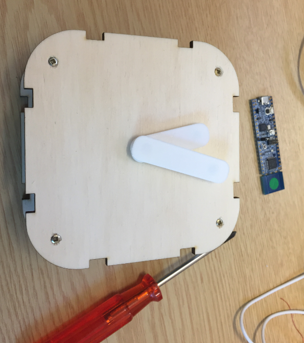
Top Face Mounted
Wireless Charging
Instead power the clock with the USB cable, optionally a wireless charging receiver can be placed inside the enclosure. Connect the receiver output to the 5V, e.g. at the stepper motor drive boards.
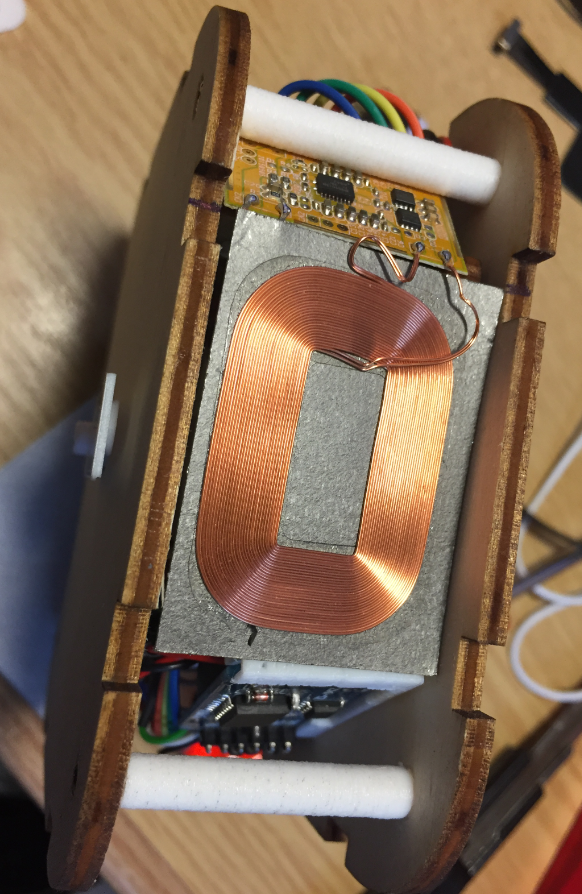
Wireless Receiver Module
Software
The software is written with NXP MCUXpresso IDE and SDK.
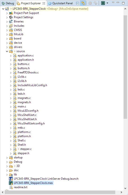
Eclipse Project in MCUXpresso IDE
The project is using the McuLib library which includes FreeRTOS and the hardware high level drivers. The system features a commandline interface using the LPC845-BRK serial port.
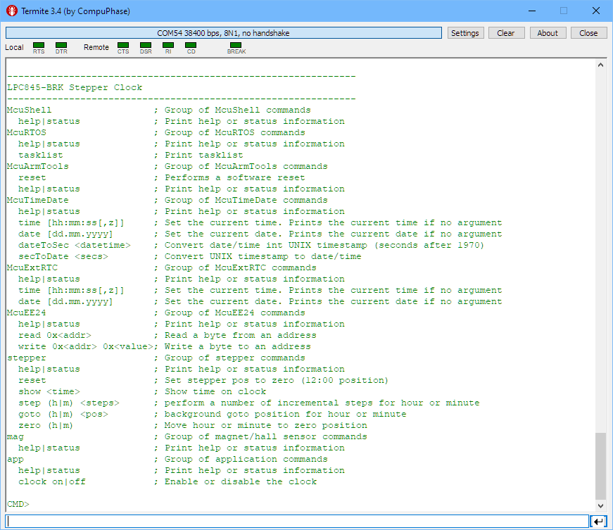
Stepper Clock Commandline Interface
The system is running with FreeRTOS:
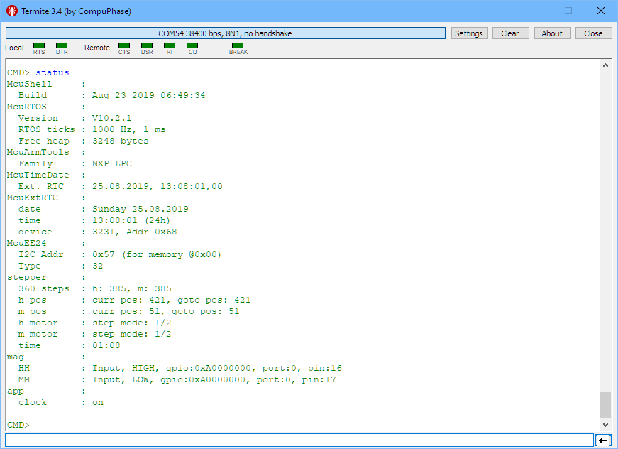
Stepper Clock Status
At power-up, the clock moves the hands to the zero position using the hall sensors. Then the hand positions get updated every minute.
Customization
The advantage of laser cutting and 3D printing is that the clock can be customized. Below are a few material and color combinations I tried.
Stepper Clock Acrylic Face White Hands

Stepper Clock Wood White Hands
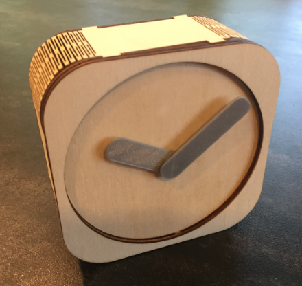
Stepper Clock Wood Silver Hands
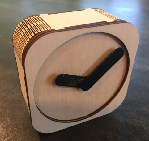
Stepper Clock Wood Black Hands
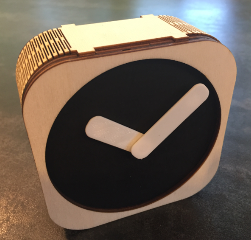
StepperClockBlackFaceWhiteHands
I probably build another one with white hands, black face, white face front and everything else in black.
Summary
It took me a while to get the design implmented, with multiple iterations. The clock is workign fine. The gear play could be better, but for a 3D printed one I’m happy with it. The clock nicely shows the time, the stepper motors are silent and working fine. And I think I need to try a few more color combinations.
Happy Clocking 🙂
PS: if you are wondering: this stepper motor clock is just one step (sic!) to a larger stepper motor project 🙂
Links
- Files on GiHub: https://github.com/ErichStyger/mcuoneclipse/tree/master/Examples/MCUXpresso/LPC845-BRK/LPC845-BRK_StepperClock
- Unboxing the NXP LPC845-BRK Board
- Tutorial: Blinky with the NXP LPC845-BRK Board
- DIY IKEA Wireless Qi Charging for the Hexiwear
- Qi Wireless Charging Transmitter with 3D Printed Enclosure

Pingback: World Stepper Clock with NXP LPC845 | MCU on Eclipse
Pingback: DIY ‘Meta Clock’ with 24 Analog Clocks | MCU on Eclipse
Pingback: Behind the Canvas: Making of “60 Billion Lights” | MCU on Eclipse
Impressive project! I am trying to use a stepper motor to do a clock with 24 hours in one circle/cycle. Just one stepper for a whole day. Python script on PI works, but how to calibrate the zero spot (pointing to 00:00 hrs or zero degrees)? – When i start it just counts degrees from that actual point….Any ideas?
LikeLike
Thanks! You might check out https://mcuoneclipse.com/2020/05/24/60-billion-lights-2400-rgb-leds-and-120-stepper-motors-hiding-behind-canvas-art/ and https://mcuoneclipse.com/2020/06/07/behind-the-canvas-making-of-60-billion-lights/, because this is basically the extended project of that initial clock project :-).
About calibration: I’m using small magnets in the hands and hall sensors on the other side/board to detect a zero position. From that you will always need some kind of offset to the 12-o-clock position which I store in the flash of the microcontroller. You can check out the above projects for this too.
LikeLike
Could u send me a link where i can download the stl files for project image “Stepper Motor Clock Concept”? in particular i need the plywood dimension? thanks
LikeLike
Did you check out the STL files in the GitHub repository linked from this article already?
LikeLike
yes, but i need playmood, and in the GitHub repository there aren’t.
LikeLike
the plywood parts are in the .svg file.
LikeLike
oh thanks, i didn’t see! Great project!
LikeLike
Great! and thanks!
LikeLike