
The NXP MCUXpressso IDE Release V11.2.1 gave a hint about a coming new debug probe, the MCU-Link which is available now:

MCU-Link in 3D printed enclosure debugging the LPC845-BRK Board
The new MCU-Link is listed on Mouser.com (search for ‘MCU-Link’) for price around $10/€10/CHF11. I two from Mouser but because Mouser is still adding it to the inventory, NXP has sent me two probes directly (thanks!).
The MCU-Link is a compact and inexpensive debug probe for NXP ARM Cortex devices (Kinetis, LPC, i.MX RT). It currently supports SWD debugging with SWO trace and includes a VCOM (Virtual COM, UART-2-USB). I’m typically using a broad range of different debug probes: from NXP LPC-Link2 to commercial P&E and SEGGER debug probes. I appreciate to have a choice, especially because that way I can use the debug probe for my projects which fits the best. So a new probe is always a welcome addition to my growing inventory of debug probes :-).
💡 Want to use the MCU-Link with OpenOCD? See https://mcuoneclipse.com/2020/12/15/openocd-with-mcu-link/
Unboxing
The MCU-Link arrived in a small box:
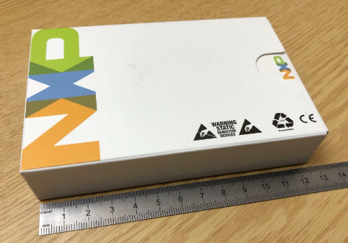
MCU-Link Box
Inside the anti-static box there is a reference guide, the PCB, three jumpers, 3pin (UART) jumper cable and the 10pin SWD/JTAG debug cable:

MCU-Link Box Content
The MCU on the MCU-Link board is the LPC55S69, (dual ARM Cortex-M33/150 MHz):

MCU-Link Board Top Side
On the bottom there are footprints for an extra push (Reset) button and a SWD debug header for the LPC55S69 (see schematics at https://www.nxp.com/downloads/en/schematics/MCU-LINK-SCH.pdf). On the bottom of board there is a header for 4 GPIO pins of the LPC55S69: So I could use that board as a minimal universal and inexpensive LPC55S69 board too 🙂 :
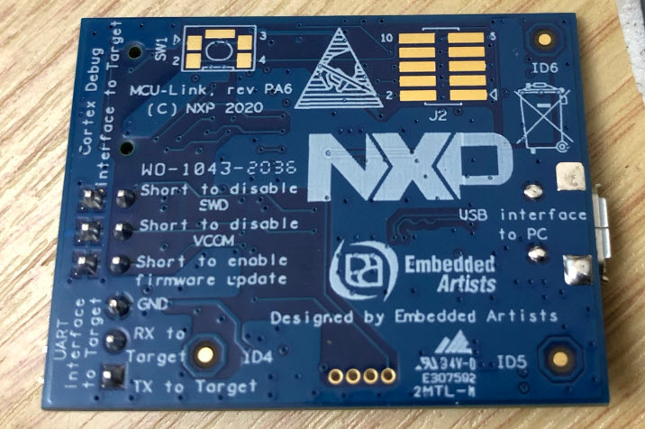
MCU-Link Board Bottom Side
The box comes with a Quick Reference Guide:
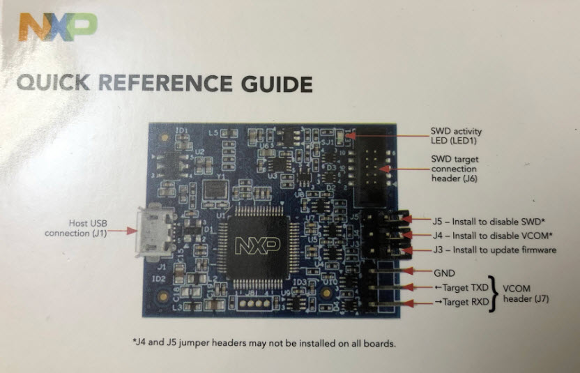
MCU-Link Quick Reference
The new MCU-Link costs only around $10, so half the price of the previous NXP LPC-Link2. The new debug probe is much more compact too:

LPC-Link2 and MCU-Link
Debugger Support
The debug probe is automatically detected in the MCUXpresso IDE and shows up as CMSIS-DAP debug probe:
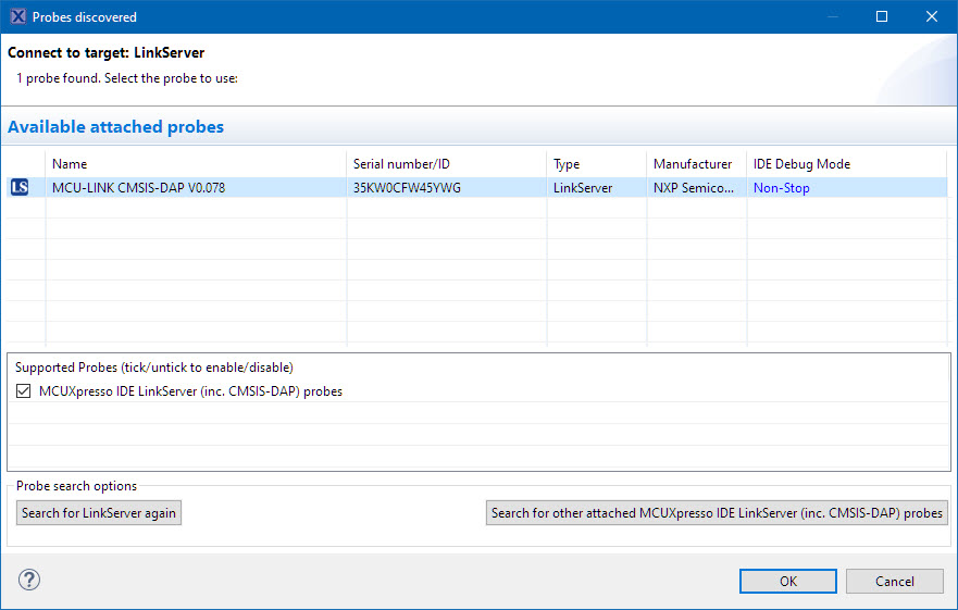
MCU-Link detected by MCUXpresso IDE
The probe is supported on Windows, MacOS and Linux (I’m using Windows 10 here).
Below I’m debugging a Kinetis K02 board with the MCU-Link debug probe:
debugging K02 with MCU-Link
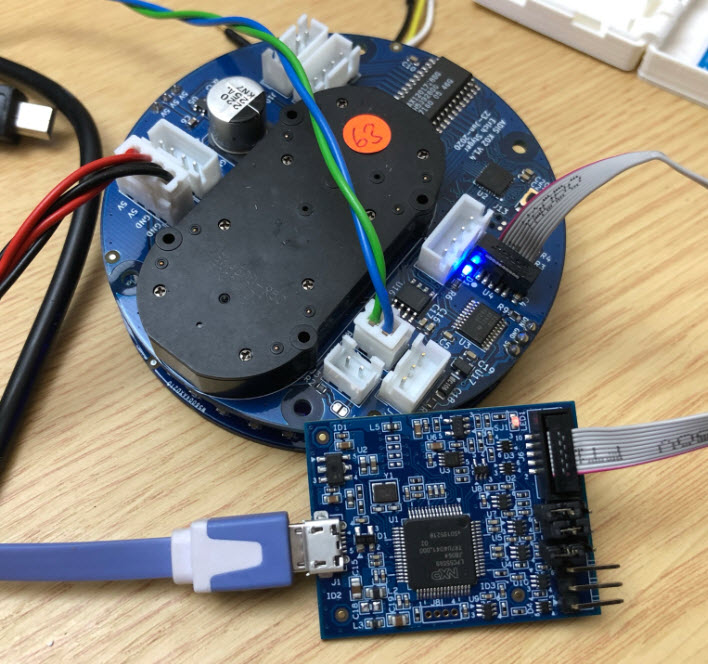
It works fine with the LPC845-BRK or with the NXP i.MX RT1064 board too:
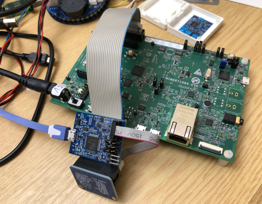
Debugging NXP i.MX RT1064 with MCU-Link debug probe
Basically it should support all the devices which are supported by the NXP LPC-Link2.
I did not compare the performance yet, but I feel it is faster than the LPC-Link2 too.
Another great thing is that the probe supports SWO trace and profiling too:
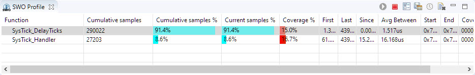
SWO Profile
Updating Firmware
The MCU-Link uses the LPC55S69 ISP bootloader and update mode. The MCU-Link board I have received had the firmware V0.078 loaded.
The firmware update utility is found on the MCU-Link web page:
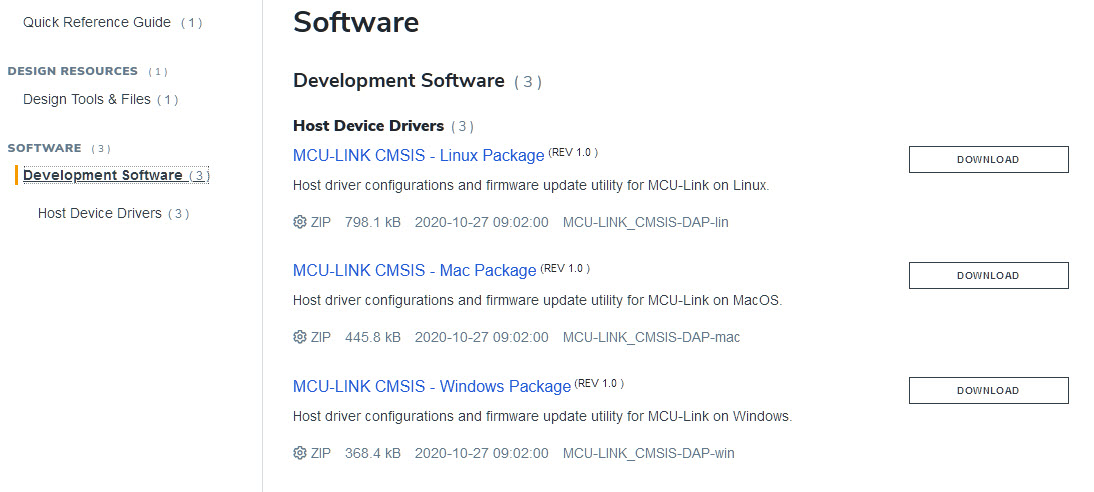
MCU-Link Firmware
At the time of this article, the most recent firmware is V1.098. Download the .zip file and extract it to a folder on the host.
Put the MCU-Link into ISP programming mode: Power the board with the Update jumper J3 installed:
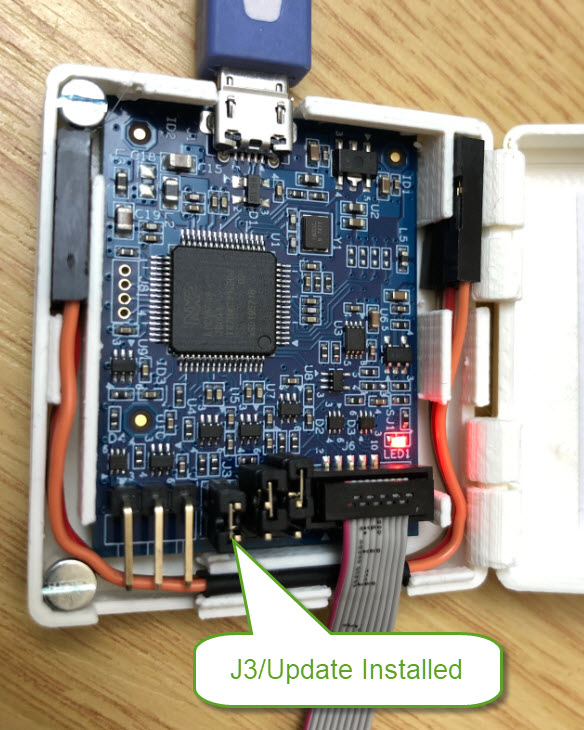
Update Jumper J3 installed on MCU-Link
Then run the program.cmd:
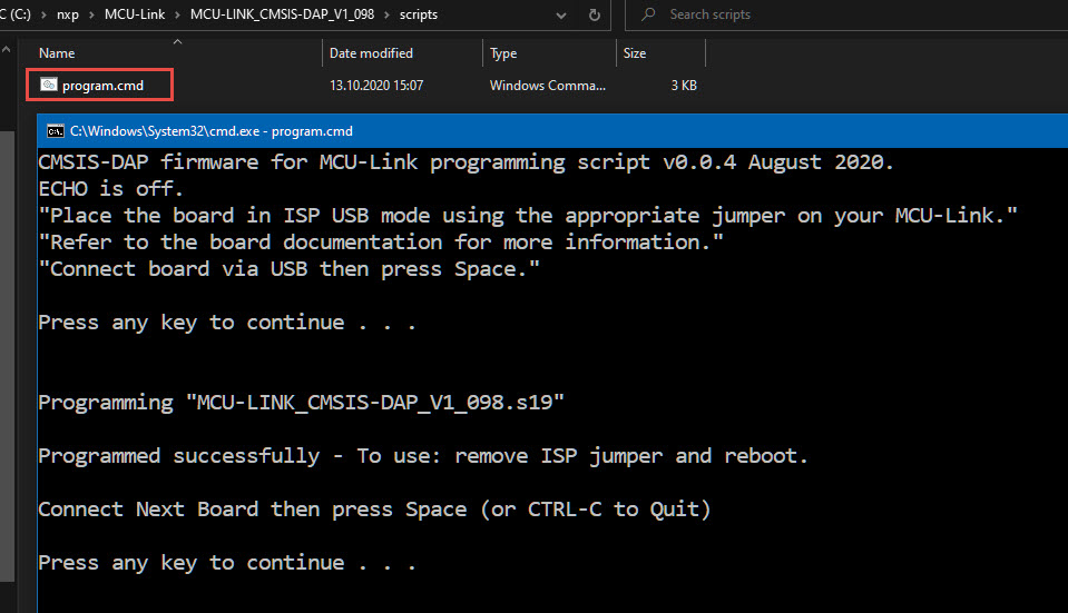
MCU-Link program.cmd
Remove the J3 jumper and re-power the MCU-Link. Now it is recognized with the new firmware in the debugger:
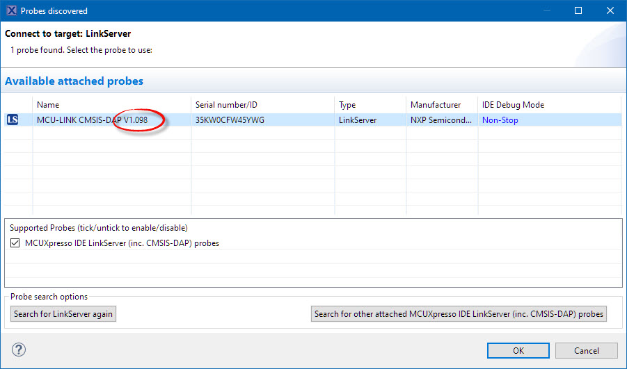
New Firmware
UART Bridge
The MCU-Link features a VCOM (UART to USB) bridge which is useful with an UART on the target. The connection includes GND, Rx and Tx.
Note that the lower pine is the Rx from the target to the MCU-Link and the middle pin is the Tx to the target from the MCU-Link:
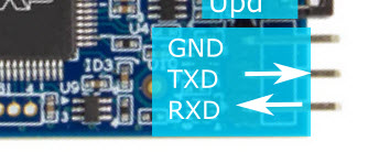
MCU-Link Tx Rx
For example I can use the MCU-Link with the ESP32:
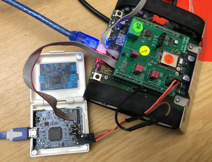
ESP32 connection with MCU-Link
I have been able to use the VCOM up to a baud of 115200: above that the connection was not working in a reliable way (I tried up to 460800):
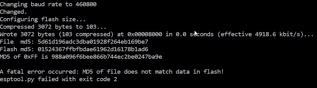
example of failure with 460800 baud
Not sure if it is a problem on my side (it works well up to 460800 for other UART adapters I’m using).
Custom 3D Printed Enclosure
The MCU-Link comes as bare board. Not to mess with other parts my crowded desk, I prefer to have an enclosure or at least some shrink-tubing around it. I have quickly designed a 3D printable design.
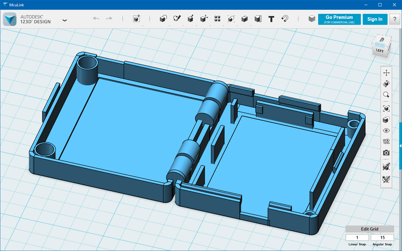
MCU-Link Enclosure Rendering
The enclosure features ‘in place printed hinges’. So everything is printed in one piece. There is an empty space inside hinge to make it movable after removed from the print bed.
You can find the design files on GitHub. I printed it with white PLA on Ultimaker-2 without any support and 0.1 mm settings:

Ultimaker 2 Settings
Inside the box there is a place for a ‘cheat sheet’ showing the jumper and UART connection pins:
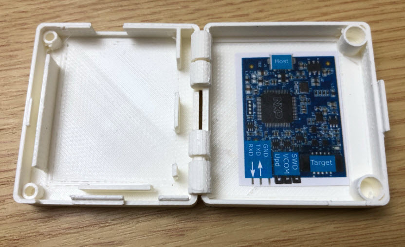
Cheat Sheet
With two 2.5mm screws and two magnets the enclosure nicely keeps closed:
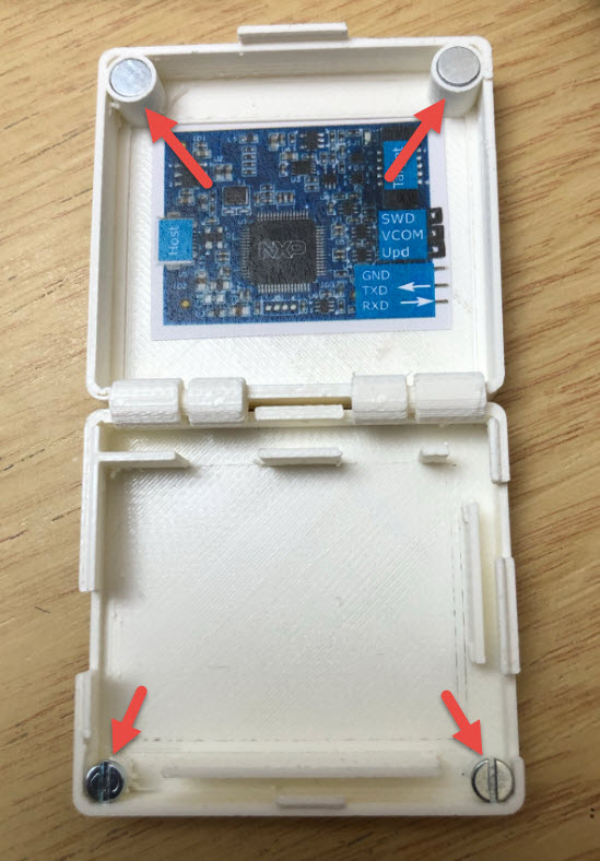
Magnet Support
Below the MCU-Link board installed which snaps into the enclosure:
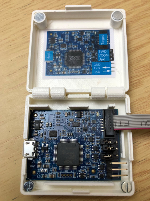
MCU-Link PCB inside enclosure
The enclosure features a space to keep the UART cable inside the box:
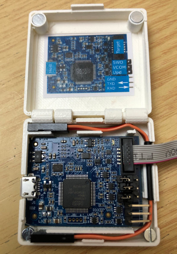
UART cables inside enclosure
And to keep things compact, the debug cable fits into the enclosure too:
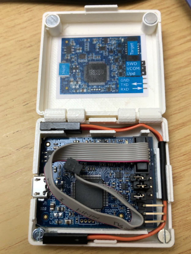
All cables inside the box
Below how the box looks closed.
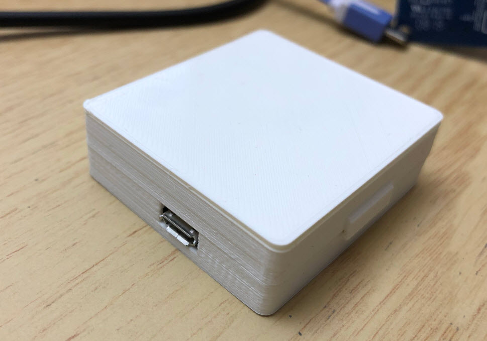
MCU-Link in a box USB connector side

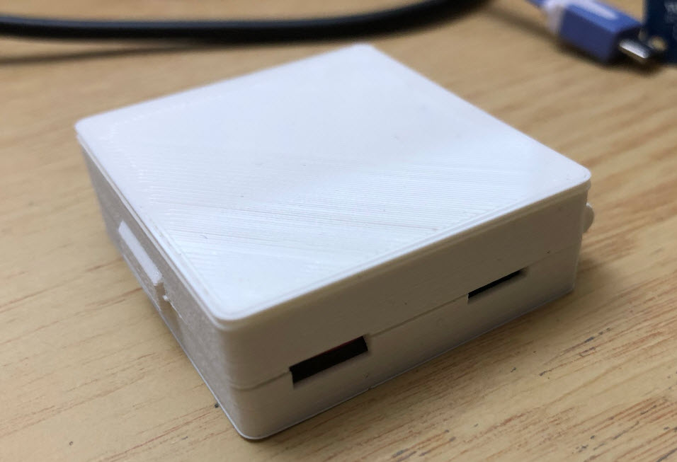
MCU-Link in a box hinge side
MCU-Link in a box debug side
Maybe I do another design to put a micro-USB cable inside the box too.
Overall the enclosure is very useful for me: it provides protection, keeps all cables in place plus includes a cheat sheet :-).
MCU-Link debugging the LPC845-BRK Board
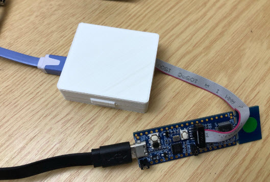
Debugging LPC845
Summary
If you are looking for an inexpensive, small and still powerful debug probe for NXP Kinetis, LPC and i.MX RT MCUs, then have a look at the NXP MCU-Link. Compared to the LPC-Link it is not only smaller, it costs only half the price and comes with a handy USB-2-Serial adapter cable. And I hope the 3D printed enclosure (design available on GitHub, see links below) is something you find useful too. I’m definitely going to add more of these probes to my inventory, and I’m sure students will like it too.
Happy Linking 🙂
Links
- NXP MCUXpresso IDE v11.2.1
- NXP MCU-Link web page: https://www.nxp.com/design/development-boards/lpcxpresso-boards/jtag-swd-debug-probe:MCU-LINK
- Community article: https://community.nxp.com/t5/MCUXpresso-Community-Articles/MCU-Link-is-now-available/ba-p/1178373
- GitHub repository: https://github.com/ErichStyger/mcuoneclipse/tree/master/MCU-Link

Nice, Does MCU-Link support power/energy profiling? Thanks
LikeLike
The schematics does not show the circuit for it.
LikeLike
do you know of a utility that a person can use to flash the target with a hex file and without using the MCUexpresso IDE and having to have a project loaded? Like segger j-flash
LikeLiked by 2 people
Hi Randy,
the obvious choice is using the SEGGER J-Flash. But it can be done with the P&E Multilink too: https://mcuoneclipse.com/2015/03/25/command-line-programming-and-debugging-with-gdb/
As for LinkServer (this is what this debug probe uses): I wanted to look into this too, so hopefully I can come up with the article I started on it in a few days if time permits.
LikeLike
Randy, also check out the open-source USBDM http://usbdm.sourceforge.net/USBDM_V4.12/ I have been using it at work for a few years now for both development and production. For production, I just push my firmware .hex along with my programming script to a git repo and my contract manufacturer pulls it and they are ready to go! I’m happy to post my script if anyone is interested.
LikeLiked by 1 person
thanx!
LikeLike
Hi Paul,
I have not looked into USBDM for a long time, so this is a good time to reconsider it. I tried your link but this seems to be broken? And yes, it would be great if you could share your script.
LikeLike
I posted my script here: https://github.com/phatpaul/batchprog-usbdm Hope it comes in handy for someone.
The link to USBDM is http://usbdm.sourceforge.net (BTW, I’m not involved with the USBDM project.)
LikeLike
Hi Paul,
many thanks for sharing!
Erich
LikeLike
You can use pyocd to do exactly that: https://github.com/pyocd/pyOCD
Assuming you have Python installed, just run ‘pip install pyocd’.
Then you can flash hex or binary files with ‘pyocd flash -t ‘.
See the target support docs (https://github.com/pyocd/pyOCD/blob/master/docs/target_support.md) for how to determine the . pyocd has a bunch of built-in MCU support, and supports every Cortex-M device with a CMSIS-Pack available (assuming the pack is not broken). Usually the target type is just the part number, such as ‘lpc824’, ‘mk02fn64vlh10’, or ‘mimxrt1064’ (to use the parts referenced in this post).
pyocd supports CMSIS-DAPv1 (MCU-Link is v1) and v2, STLinkV2/3, Segger J-Link, and PEMicro probes (via the pyocd-pemicro package installable via pip, written by Petr Gargulak from NXP 😊, which will soon be installed by default with pyocd).
LikeLiked by 1 person
Sorry, that’s supposed to be:
‘pyocd flash -t target-type hex-file’.
and
“how to determine the target type”
(I used angle-brackets which were stripped since it looks like an HTML tag.)
LikeLiked by 1 person
Hi Randy,
You can simply using your current environment and use a script/batch file for flashing your file. Check out https://mcuoneclipse.com/2020/12/05/standalone-and-command-line-programmer-with-mcuxpresso/. As for the MCU-Link, it supports ELF/Dwarf and .bin format. Bu you can easily generate a bin or convert your .hex into a .bin with the SRecord tool too, if you want to stick to .bin.
I hope this helps,
Erich
LikeLike
Thanks for creating the excellent box design for tis Erich!
LikeLiked by 1 person
Pingback: Standalone and Command Line Programmer with MCUXpresso | MCU on Eclipse
Hi.
Do you know how it can be programmed with the MCU Link so that the microcontroller is protected against reading?
I am interested in this programmer, I have already ordered it from Farnell, I hope to receive it soon.My only doubt is how to use it to program a commercial finished product in production, which must be protected to prevent someone from extracting the program.
Being able to program with external commands without using MCUXpresso is fine, but unless it can be read-protected, it won’t be very useful to me.
In general, I would like to know if there is any parameter in MCUXpresso that allows to protect the code against reading. I have read something from a flash configuration file in Startup, I don’t know if this is it and what to do exactly:
// ************************************************ *****************************
// Flash Configuration block: 16-byte flash configuration field that stores
// default protection settings (loaded on reset) and security information that
// allows the MCU to restrict access to the Flash Memory module.
// Placed at address 0x400 by the linker script.
// ************************************************ *****************************
__attribute__ ((used, section (“. FlashConfig”))) const struct {
unsigned int word1;
unsigned int word2;
unsigned int word3;
unsigned int word4;
} Flash_Config = {0xFFFFFFFF, 0xFFFFFFFF, 0xFFFFFFFF, 0xFFFFFFFE};
LikeLike
Enabling debug security depends entirely on the MCU design, and has no relation to the debug probe. The reference manual for the MCU you are using will describe how to enable debug security for that device or family. Usually it is done by putting some configuration in a defined reserved in flash. So any debug probe that can program flash can enable security.
For the NXP Kinetis devices, the FCF that you show contains an FSEC field that is used to enable security. LPC devices have a feature called CRP (Code Read Protection) with a setting that also resides in flash. Security for nRF devices is controlled through the UICR flash region. STM32 devices again have something similar. See the RM for your device for details. There are also often app notes that describe how to enable debug security.
LikeLike
Hi luis,
the protection level and bits depend on the microcontroller used, so have a read in the its reference manual. I wrote an article on that subject here: https://mcuoneclipse.com/2012/11/04/how-not-to-secure-my-microcontroller/
LikeLike
Pingback: OpenOCD with MCU-Link | MCU on Eclipse
Pingback: New MetaClockClock V3 finished with 60 Clocks | MCU on Eclipse
Pingback: MCUXpresso IDE V11.3.0 for 2021 | MCU on Eclipse
Pingback: Debug Firmware Switching for the LPC4322 | MCU on Eclipse
Pingback: New MCUXpresso IDE v11.3.1 | MCU on Eclipse
Pingback: SWO with ARM Cortex-M33 | MCU on Eclipse
Pingback: New “MCU-Link Pro”: Debug Probe with Energy Measurement | MCU on Eclipse
Hello
What is the aim of the file mculinkcover.stl?
Thanky
LikeLike
I used it to print plates/covers in different colors, to distinguish different probes more easily.
LikeLike
Ok, So If I understand, I must print both file, the cover comes “clip” on the main box? or the “Cover” is an optional additional piece?
LikeLike
Yes, the ‘cover’ is an optional piece only.
LikeLike
Does MCU-LINK can be used instead of MULTILINK in CodeWarrior 11 for ARM processors?
LikeLike
Yes, you can use it with OpenOCD (see as well https://mcuoneclipse.com/2020/12/15/openocd-with-mcu-link/) as CMSIS-DAP debug probe.
However, it really depends on the device you are using, as OpenOCD support is very limited for NXP and Freescale devices. You have to lookup the OpenOCD support for your device and try it out.
LikeLike
Pingback: Making a debug probe for robots and Pixhawk with KiCad « Adafruit Industries – Makers, hackers, artists, designers and engineers!