
One major concern of embedded system development is performance. Microcontroller have more MHz than in the past, but embedded applications are all about timing and real-time aspects.

The challenge is: how to get data off the target in realtime? SWO can help with this….
In this article I’m using the NXP LPC55S16-EVK (ARM Cortex-M33), but because DWT/SWO is shared across ARM Cortex-M3, M4, M33, M7 and everything is pretty generic. Just keep in mind that M0(+) and M23 does not have the SWO feature.

Why SWO (or not)
SWO is a feature ARM has added to certain ARM Cortex devices (see Tutorial: Using Single Wire Output SWO with ARM Cortex-M and Eclipse for details) which is very useful: with a single pin the application can communicate with the outside world at high speed. One usage is to use it as a ‘ITM Console’ to send text or data.

Another useful feature is ‘PC sampling’: the core sends samples of the PC (Program Counter) to the host and with this I can build an application profile:
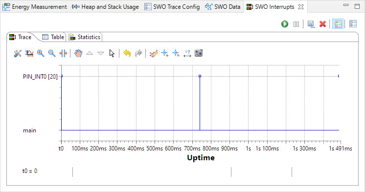
Another useful feature is interrupt recording: it sends a data packet for each interrupt:
Or collecting general performance information:

There are a lot good reasons to take advantage of SWO. Still there some road blocks:
- Not every ARM Cortex-M has it implemented: there is no support on M0, M0+ or M23.
- It requires a dedicated pin reserved for SWO. A microcontroller probably never has enough pins, that SWO pin is used for other things like UART or GPIO.
- The SWO pin needs to be clocked and muxed for which you might not have a working example.
- The SWO hardware (Debug Block) clocking needs to be properly configured and clocked: The information for it is buried deep in reference manuals.
- The used hardware blocks DWT (Data Watchpoint and Trace), ITM (Instrumentation Trace Macrocell) and TPI (Trace Port Interface) are part of the ARM core description and very cryptic. Plus because they are part of the ARM core architecture description, you won’t find them it your microcontroller documentation.
- SWO is basically an unidirectional UART, and both the host PC and the target need to agree on the communication rate.
- Debuggers and standalone SWO tools try to set up things on the target for you: detecting clock speed, setting prescalers and configuring things. The issue is that this is not transparent and messes up with any setup you have for it in the application. Even worse it can make your application not working any more if it depends for example on shared functionality like cycle counters.
SWO Debug Probe
To use SWO I need a SWO-capable debug probe (e.g. P&E Multilink, NXP MCU-Link or Segger J-Link). In this article I’m have programmed the on-board debug probe of the LPC55S16-EVK with a J-Link firmware which does support SWO. See Debug Firmware Switching for the LPC4322 how to do this.

SWO Capture
I recommend to capture the SWO pin with a logic analyzer or oscilloscope. On the LPC55S16-EVK the signal is available on one of the Arduino headers:

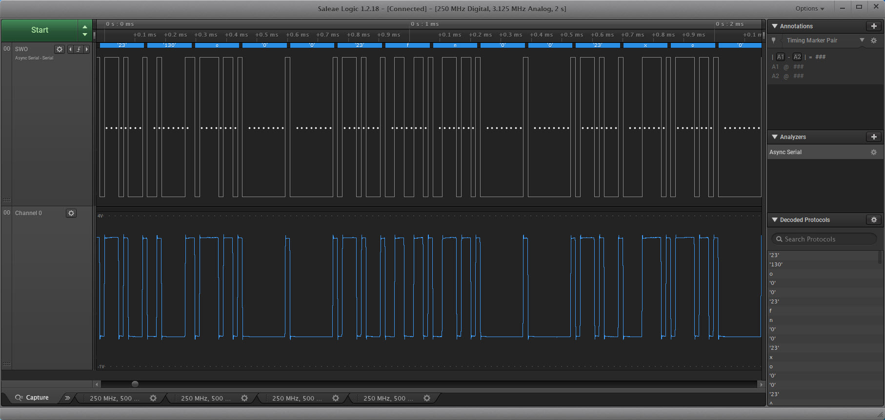
That way I can capture and verify the signal with a normal Async/UART encoding:
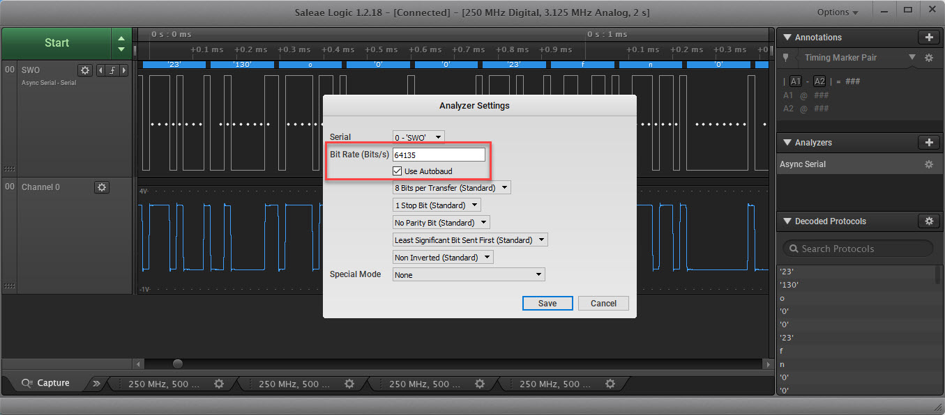
Verify that the bit/baud rate is matching our expectations:
Muxing
The SWO pin needs to be configured and muxed by the application. Check the schematics which of the pins is connected to the SWO pin on the debugger header and mux it for SWO functionality:

Clocking
Make sure the SWO functionality is supplied with a clock, preferable with a prescaler set matching up to the CPU core/system clock:

McuSWO
Configuring and working with SWO can be daunting and complex. To make things easier I have create the McuSWO module which simplifies a lot of things. The module is available on GitHub and used in that project. It contains routines to setup SWO e.g. for sending characters:
/*!
 * \brief Initialize the SWO trace port for debug message printing
 * \param portBits Port bit mask to be configured
 * \param cpuCoreFreqHz CPU core clock frequency in Hz
 */
static void Init(uint32_t portBits, uint32_t traceClockHz, uint32_t SWOSpeed) {
  /* Enables the clock for the I/O controller: Enable Clock. */
  MuxSWOPin();

  /*!< Set up dividers */
  CLOCK_SetClkDiv(kCLOCK_DivAhbClk, 1U, false);         /*!< Set AHBCLKDIV divider to value 1 */
  CLOCK_SetClkDiv(kCLOCK_DivArmTrClkDiv, 0U, true);     /*!< Reset TRACECLKDIV divider counter and halt it */
  CLOCK_SetClkDiv(kCLOCK_DivArmTrClkDiv, 1U, false);    /*!< Set TRACECLKDIV divider to value 1 */

  /*!< Switch TRACE to TRACE_DIV */
  CLOCK_AttachClk(kTRACE_DIV_to_TRACE);

  CoreDebug->DEMCR = CoreDebug_DEMCR_TRCENA_Msk; /* enable trace in core debug */
  *((volatile unsigned *)(ITM_BASE + 0x400F0)) = 0x00000002; /* "Selected PIN Protocol Register": Select which protocol to use for trace output (2: SWO NRZ, 1: SWO Manchester encoding) */
  SetSWOSpeed(traceClockHz, SWOSpeed); /* set baud rate */
  ITM->LAR = 0xC5ACCE55; /* ITM Lock Access Register, C5ACCE55 enables more write access to Control Register 0xE00 :: 0xFFC */
  ITM->TCR = ITM_TCR_TRACEBUSID_Msk | ITM_TCR_SWOENA_Msk | ITM_TCR_SYNCENA_Msk | ITM_TCR_ITMENA_Msk; /* ITM Trace Control Register */
  ITM->TPR = ITM_TPR_PRIVMASK_Msk; /* ITM Trace Privilege Register */
  ITM->TER = portBits; /* ITM Trace Enable Register. Enabled tracing on stimulus ports. One bit per stimulus port. */
  DWT->CTRL = /* see https://interrupt.memfault.com/blog/profiling-firmware-on-cortex-m#enabling-pc-sampling-with-itm-and-openocd */
          (  4<<DWT_CTRL_NUMCOMP_Pos)    /* 4 bits */
#if McuSWO_CONFIG_PC_SAMPLING
        | (  1<<DWT_CTRL_PCSAMPLENA_Pos) /* 1 bit: enable PC sampling */
#endif
        | (  0<<DWT_CTRL_SYNCTAP_Pos)    /* 2 bits */
        | (  1<<DWT_CTRL_CYCTAP_Pos)     /* 1 bits: This selects which bit in the cycle counter is used to trigger PC sampling events. A 1 selects bit 10 to tap, a 0 selects bit 6 to tap. */
        | (0xF<<DWT_CTRL_POSTINIT_Pos)   /* 4 bits */
        | (0xF<<DWT_CTRL_POSTPRESET_Pos) /* 4 bits: These bits control how many times the time bit must toggle before a PC sample event is generated. */
#if McuWait_CONFIG_USE_CYCLE_COUNTER || McuSWO_CONFIG_PC_SAMPLING
        | (  1<<DWT_CTRL_CYCCNTENA_Pos)  /* 1 bit: enable CYCCNT which is required for PC sampling */
#endif
    ;
  TPI->FFCR = (1<<TPI_FFCR_TrigIn_Pos); /* Formatter and Flush Control Register */
}
The implementation includes a command line interface to inspect and change the SWO settings:

SEGGER SWO Viewer
Segger delivers a command line tool show the SWO output. This is great as I can use an application without a debugger. Start the tool with
JLinkSWOViewerCL.exe -device LPC55S16 -swofreq 64000 -cpufreq 0 -itmport 0x1
Note that I want to have it using a SWO frequency of 64 kHz. I’m using the version V7.20a. That version tries to find the best settings, but somehow configures a different baud (this should be fixed in a next release, additionally there might be a version with an ‘attach’ mode which won’t change the registers on the target).
Update: SEGGER released that ‘attach’ mode with V7.22:
– [SWOViewer]: Added command line option “-swoattach <OnOff>” that disables all J-Link side initialization of SWO and relies on the target application to perform SWO init.
The used baud rate can be inspected:
McuSWO status
Using the McuSWO this can be easily changed back to 64 K:
McuSWO baud 64000Checking the baud again with
McuSWO status
With this I can send data to the SEGGER SWO Viewer successfully:

The same way I can configure the SWOFreq for the GUI SWO Viewer:

With the SEGGER tools I do not need a debugger running which is great.
SWO in MCUXpresso IDE
The Eclipse based MCUXpresso IDE has several SWO features included behind the ‘Analysis’ menu:

With this I get nice graphical views during debugging:

Here again as seen in the screenshot it might be necessary to update/change the SWO speed.
Summary
SWO is a really useful features in some ARM Cortex-M (3, 4, 7, 33) architectures. It is used to stream out data from the target and requires a dedicated pin and setup. One can take advantage of SWO with Eclipse (MCUXpresso IDE) or with standalone viewers from SEGGER. A crucial tool to verify SWO data is correct is using a logical analyzer, in combination with the McuSWO module/implementation to configure the device so it can run standalone: that way I don’t need a debug session running and can stream the SWO data all the time if needed. The McuSWO module is still work in progress and I plan to add it to the suite of tools in the McuLib.
Happy SWO’ing 🙂
Links
- Tutorial: Using Single Wire Output SWO with ARM Cortex-M and Eclipse
- SWO with NXP i.MX RT1064-EVK Board
- ARM SWO Performance Counters
- Debug Firmware Switching for the LPC4322
- Project used in this article on GitHub: https://github.com/ErichStyger/mcuoneclipse/tree/master/Examples/MCUXpresso/LPC55S16-EVK/LPC55S16_Blinky

Interesting – I see this as really another tool in an engineer’s toolbox.
Since you have to have a debugger attached to the MCU, I don’t really see huge differentiator to using SWO versus “PRINTF” (as we’ve been discussing over the past few weeks) other than SWO uses fewer pins.
As always, thank you for posting this.
LikeLiked by 1 person
Hi myke,
you do not need a debugger (or debug session) attached. You only need some piece of hardware capable to capture the data. Debug probes usually are able and fast enough to do it, but you can use anything (oscilloscope, logic analyzer, other micro controller) to capture the data. And yes, it is similar to UART, but uses the number of pins as the data stream is unidirectional (just sending from the CPU). It is possible to have an ITM console with write *and* read, but in this case the debugger needs to write the data into a buffer, see ITM_ReceiveChar() in the CMSIS-Core.
Where SWO really is superior to UART is that it does not need instrumentation to get trace information out: it can send out samples of the current PC or logging the interrupt activity.
LikeLiked by 1 person
Hi Erich,
I should have expanded my comment on this being a tool for the “engineer’s toolbox”.
I managed a team of engineers and non-engineers developing products for Logitech Harmony (Programmable IR/RF remote controls for home entertainment) years ago and when I started we used Microchip’s APPIO interface for debugging with MPLAB. It was a real headache training the 40+ non-engineers in how MPAB/ICD/APPIO worked and supporting them in doing graphic design, UI and script development as well as other non-firmware engineering development tasks on engineering tools.
We moved to an i.MX processor for the Harmony 1000 and used High Availability Boot (HAB) for programming. This tool allows Flash programming through the USB port without any custom hardware and the port can be used normally after the programming operation. The HAB tool runs on Windows and Linux PCs and was very simple (select an image to load, click on the “Load” button). Standard tools were used by the non-engineers for their functions and they were a lot more effective and the costs of supporting them went down to basically zero (USB cables still wore out).
So what an engineer may consider to be minimal instrumentation (ie oscilloscope, logic analyzer, other micro controller) that’s a lot for someone without that background to work with. With the Jade Robot, I do the firmware development and the UI and app designers are using tools better suited to their job functions than Eclipse (or Visual Studio).
That was my point: SWO is another tool for the engineer, but it’s not really helpful for many of the development functions needed to bring a product to market.
LikeLiked by 1 person
Hi myke,
thanks for that additional information, that makes absolutely sense. I think it might depend on the term ‘engineer’ or ‘engineering’ in such a case. Using non-engineers to do ‘engineering’ sounds like a bad idea. My experience managing large (worldwide) engineering (or development) teams is to carefully get them working in the areas they understand and master, and then gradually train them in other areas if needed. And to have them working in areas where they excel best: the most valuable ones were usually the ones who understand the hardware and circuit and the same time they master software and tools: they were able to solve the hard problems in the projects. There were other classes of developers which where really good dealing with the pieces of DevOps, CI/CD and software packages.
And interesting point about the Logitech Harmony: I loved that one, but I do not remember the exact model I used. It worked well until the contacts weared out making charging really flaky. It was such a bad experience that I never wanted to buy another one (never checked their recent versions). I use that as an example that even if something is great it can fail because of some unrelated design issues.
LikeLiked by 1 person
Pingback: Standalone SWO | MCU on Eclipse
A debugger indeed is needed in order to get this working. The reason is on power up the default interface is JTAG, and the SWO pin will only work when the interface is in SWD mode. An external signal sequence is needed in order to switch to SWD mode, The debugger perform this sequence.
https://developer.arm.com/documentation/ddi0316/d/Chdhfbhc
LikeLike
Thanks for the link. But you do not really need a debugger, you can do this from the application too. That’s why I wrote the McuSWO module which does all the ‘magic’ in the application and does not require a debugger to set it up: https://mcuoneclipse.com/tag/mcuswo/
LikeLike