
After the release of the NXP MCU-Link debug probe, there have been hints in the Eclipse based MCUXpresso IDE that there must be another one coming. And indeed: another and more powerful debug probe is now available: the MCU-Link Pro. It is not only a debug probe but a power/energy measurement tool too, including an extra LPC804 mikrocontroller which can be used for all kind of things, like automation or scripting.

Overview
The MCU-Link Pro (66×73 mm) is a kind of ‘big brother’ of the smaller MCU-Link (41×32 mm). The MCU-Link Pro is much more versatile and includes an extra LPC804 mikrocontroller. The biggest difference is that the Pro can measure energy/power consumption of a target board while debugging it. An extra is that the MCU-Link can be turned into a J-Link while this is not the case for the non-Pro version.
I saw the MCU-Link Pro listed on Mouser (Part number: 771-MCU-LINK-PRO), and they should have it on stock early November. The unit is listed for CHF 42.35 (US$40) compared to the CHF 11.65 (US$10) I usually order from Mouser, and NXP has sent me one to try it out. As of today (17-Oct-21), both Future and Arrow have it on stock (not sure how long I guess).
My view is that the combination of the MCU-Link Pro is replacing the NXP LPC-Link2 debug probe (around US$24), with the addition of current/voltage/power/energy measurement. The non-Pro as a inexpensive entry level solution, with the Pro version providing extra features like powering the target and the energy measurement.
Comparison
The following table gives an overview about the differences between the two probes:
| Item | Mcu-Link Pro | MCU-Link |
| MCU | LPC55S69 (ARM Cortex M33@150 MHz) LPC804 (ARM Cortex M0+@15 MHz) | LPC55S69 (ARM Cortex M33@150 MHz) |
| PCB size | 73 x 66 mm | 41 x 32 mm |
| Debug | CMSIS-DAP, J-Link | CMSIS-DAP |
| Target Voltage | 1.2 V – 5 V | 1.2 V – 5 V |
| SWD | yes (10-pin and 20-pin) | yes (10-pin) |
| SWO | yes | yes |
| Target Reset Button | yes | no |
| VCOM | yes | yes |
| LEDs | 7 + 2 (LPC804) | 1 |
| I/O Connector | yes (LPC55S69 & LPC804) with I2C and SPI bridging | (yes) 4 pins, unpopulated |
| Target Power | yes, 1.8 V & 3.3 V, 400 mA | no |
| Firmware Update | ISP jumper with update script, automatic for J-Link firmware | ISP jumper with update script |
| Energy Measurement | yes | no |
| Price | US$40 | US$10 |
Unpacking
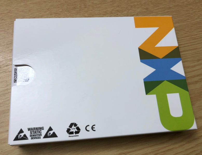
So here is what you get with an MCU-Link Pro: The hardware comes in a card-box:
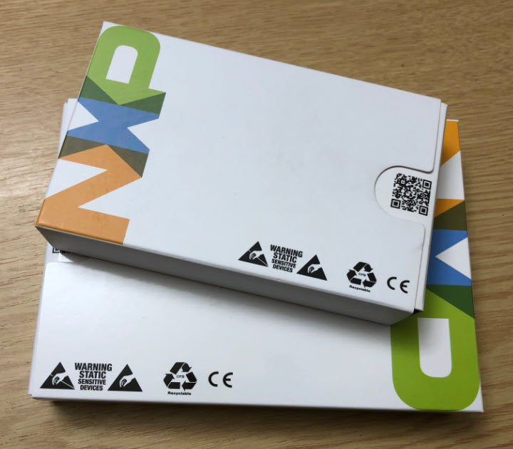
It uses the same package concept as the smaller MCU-Link, shown below in comparison:
I like the fact that it is a recyclable package. The inside includes an overview picture and a quick reference card:


Inside there are two anti-static bags:

The bags contain the PCB plus cables and set of four jumpers:

There is no Micro-USB cable included which is a good thing: I don’t ‘yet another USB cable’, so from an environment point of view this is very positive too. The kit includes a 3-pin Power-Measurement cable plus a 14-pin I/O cable.
The kit contains two debug cables. The board has both the 10 and 20 pin (unpopulated) debug headers.

There are no extra signals on the 20pin header, so it is more a convenience working with boards having the 20pin connector. A neat solution is that special 10-to-20 pin cable included in the kit which works great for ‘shrouded’ 20pin headers:

Hardware
The board does not come with a special enclosure or stand-offs: from a using standpoint that’s probably not ideal, but this opens up ideas for a custom enclosure, just in case. For the intended target audience of hardware & software engineers this is probably not an issue.
The picture below shows the most important parts of the board:
The I/O connector makes SPI, I2C, UART and trigger functions available. On the lower left there is the power/energy measurement circuit and connection. On the lower right there is LPC804 with its own debug header and I/O connector available: basically the MCU-Link Pro includes a LPC804 evaluation board which can drive signals or can run standalone. The heart of the board is the LPC55S69 processor which comes with its own debug header and UART connector. The LPC55S69 can be reprogrammed over USB with the firmware update jumper installed. More about this in the next section.
The Multi-Probe Sync connector is “reserved for future use” according to the user manual.
The I/O connector or port features several signals which can be used for example with the LIBUSBSIO USB serial I/O library:

I really like the LPC804 on the board. According the schematics it is used as ‘Demo Signal Generator’ and it can be used for creating dummy loads for current consumption or to connect signals to the LPC55S69 I/O connector. So I think for MCU-Link Pro demos or lab sessions with it (will there be any NXP hands-on labs/conferences after the pandemic?) it would be a great feature: you can use the board without the need for any external board as you can use and debug the on-board LPC804. I think it would be a great idea to use the LPC804 for automation or scripting, for example talking to the LPC55S59 debug chip in an automated test farm. I have not explored that yet, but if the LinkServer (or J-Link) firmware on the board would allow me to do this, this would be a great thing: I could use the LPC804 to turn on/off a relay to switch on/off power, talk to the LPC55S69 firmware to download/debug the DUT (device under test), … Ultimately I can reprogram and debug the LPC55S69 on the board, as there is a dedicated debug header for it.
Firmware
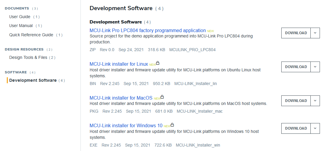
The probe comes factory programmed with a V2.41 firmware (LinkServer). The probe can be updated with the same firmware tools/updater as the MCU-Link.

The same can be found on the Pro web page, including the factory programmed LPC804 application:
To program the LinkServer (CMSIS-DAP) firmware, the installer provides a ‘program_CMSIS.cmd’ script, which requires the ISP/Bootloader J4 jumper installed at board boot time. The steps are the same as for the MCU-Link, see this article or see the next steps.
SEGGER Firmware
The probe can be reprogrammed with a firmware to turn it into a SEGGER J-Link.
💡 Note that only the ‘Pro‘ version of MCU-Link can be re-programmed as a J-Link.
First, put the jumper on J4 and power the board to put it into bootloader mode.
Then run the program_JLINK.cmd (double-click to run it). The ‘program_CMSIS.cmd’ is used to program the board with the LinkServer/CMSIS-DAP firmware.

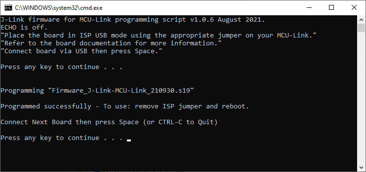
This gives this:

Then press a key and it will program the firmware:
Then press CTRL+C to leave the programming, remove the jumper on J4 and re-power the board.
Contratulations, with this the MCU-Link Pro has turned into a SEGGER J-Link 🙂
Newer firmware might be available on the SEGGER (https://www.segger.com/downloads/jlink/#MCU-Link) web page:

A new firmware file can be placed into the firmware folder:

To program a different firmware, launch the command prompt
Then use the script plus as first argument the new firmware file to use:
For example:
program_JLINK.cmd ../probe_firmware/Firmware_J-Link-MCU-Link_210930.s19will program the MCU-Link Pro with that given firmware.
Debugging
Debugging worked out-of-the box with the NXP MCUXpresso IDE 11.4.1 using the LinkServer or J-Link firmware.

Below the NXP MCUXpresso IDE at work with the MCU-Link Pro:

The J-Link firmware works fine with Visual Studio Code too (there is no LinkServer support in VSC).

Power Measurement
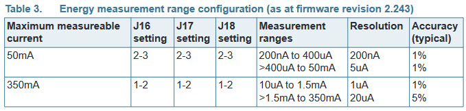
The MCU-Link Pro is able to provide power to the target. In addition to this it has the ability to measure current flowing through energy measurement connector (J9). Using J16, J16 and J18 the measurement ranges can be selected:
To use the power/energy measurement, the LinkServer firmware is required (does not support the J-Link firmware).
Pay attention to the measurement and the current flow: if in doubt, swap the cables 😉

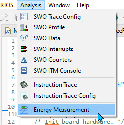
The energy measurement is accessible through a menu:
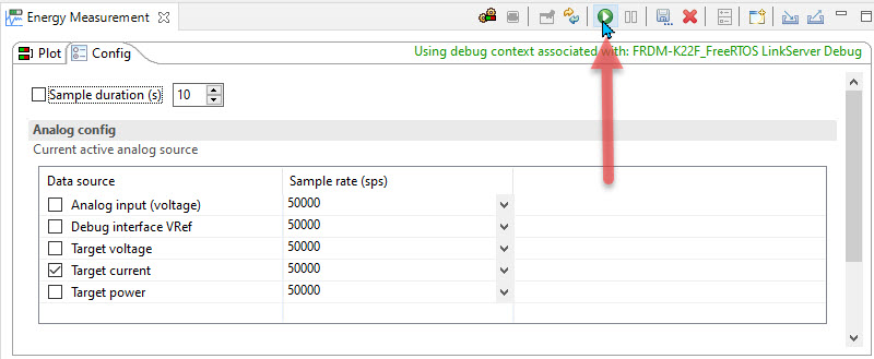
From that menu the probe can be be selected:

After that I can configure the analog part (what to measure, and the sample rate):

With the ‘play’ button I can start the data collection:
The data is shown in the view where I can zoom and inspect the measurements:

For the energy measurement I can read the target voltage:

With the target voltage it calculates the energy:

A useful feature is the analog signal measurement (0-3.3V) with signal on the I/O connector:


So the probe can measure current, the power/Energy and an arbitrary voltage (only one at a time).
Summary
The MCU-Link Pro is more capable than the MCU-Link (non-Pro): it adds power/energy measurement, an extra LPC804 mikrocontroller plus the ability to use it as a SEGGER J-Link.
The Pro is to me a replacement of the LPC-Link2, with the addition of the LPC804 plus the ability to measure current/power/energy and voltage. Plus I like the ability to debug and measure the same time.
For the price it is a good combination, especially if I want to debug a target, and the same time want to measure the energy/power consumption. In one of my university lecture/lab we deal with microcontroller low power modes: so far we I have used in the labs an external measurement circuit: switching to the MCU-Link Pro instead would make the setup and the lab much simpler, so I have to consider this for the course in the next semester.
I still have the LPC-Link2 probe in use, but I think I will it replace over time with the more capable MCU-Link Pro. Especially for the labs where we use power/energy measurement, the MCU-Link Pro will be my choice. For any other project or where J-Link support is not needed, the MCU-Link (non-Pro) will do it too.
Happy Linking 🙂
Links
- NXP MCU-Link Pro web page: https://www.nxp.com/design/microcontrollers-developer-resources/mcu-link-pro-debug-probe:MCU-LINK-PRO
- NXP MCU-Link web page: https://www.nxp.com/design/microcontrollers-developer-resources/mcu-link-debug-probe:MCU-LINK
- SEGGER MCU-Link web page: https://www.segger.com/products/debug-probes/j-link/models/other-j-links/mcu-link/
- MCU-Link (no-Pro) debug probe: New MCU-Link Debug Probe from NXP

Informative, thank you very much.
LikeLiked by 1 person
I wonder if this works with SES? which requires a J-Link debugger. I know it works with the J-Link debug driver for NXP’s dev boards. If so, I will have to get one asap!
LikeLiked by 1 person
Yes, SES supports it as it is a J-Link too. However, the energy measurements require the LinkServer/CMSIS-DAP protocol which is not supported by SES. As for getting one: I wanted to order several units for my next course, but the ones I saw available on Mouser are all gone :-(. I should have ordered them before publishing my article I guess.
LikeLike
There in stock for me, I just ordered 2x!!
LikeLiked by 1 person
Oh, right, Mouser shows again a few available, going to place my order. Thanks!
LikeLike
Pingback: Adding RGBW Wings and Enclosure to a Debug Probe | MCU on Eclipse
Pingback: Low-power optimization techniques for ARM Cortex-M microcontrollers « Adafruit Industries – Makers, hackers, artists, designers and engineers!