I’m using debug probes on a daily base. They have to be functional, and I value functionality over aesthetics. For cost reasons many debug probe vendors either only provide a bare PCB without enclosure, or the enclosure is made of simple plastic enclosure.
That’s OK. But when I received my NXP MCU-Link Pro debug probe, I wanted to add an enclosure for it: Not only to add protection,but to have it look cool too :-).
Outline
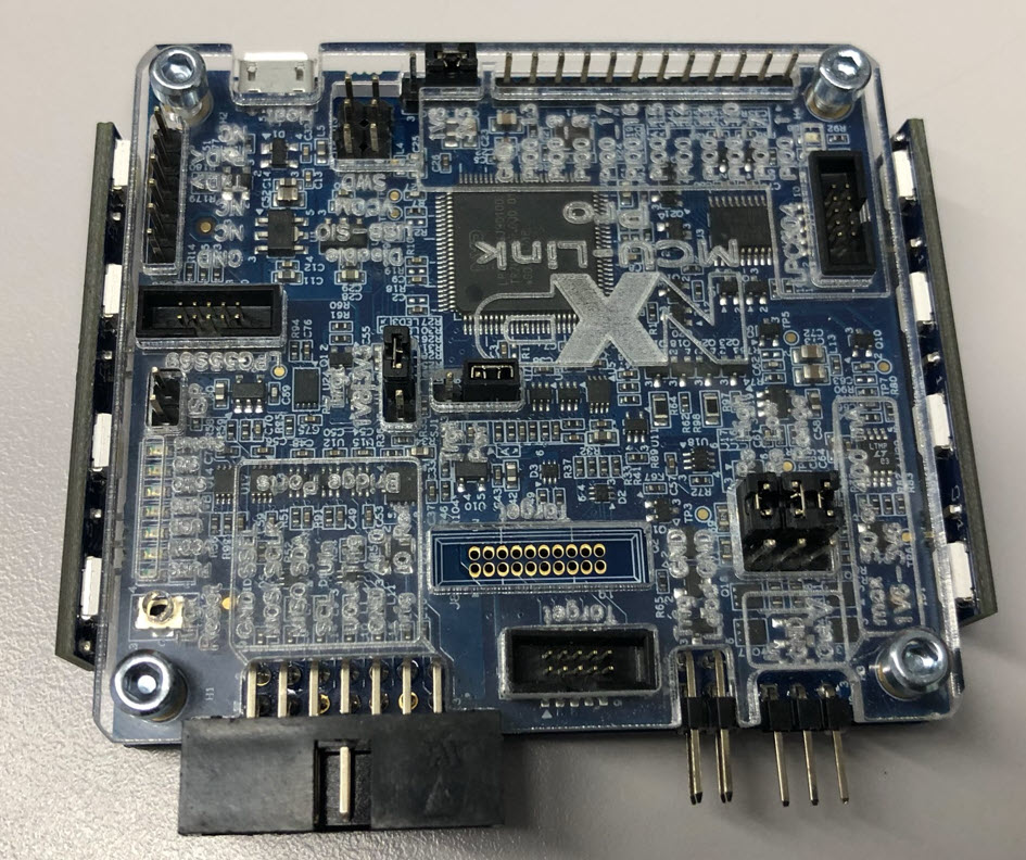
The NXP MCU-Link Pro debug and power measurement probe comes as bare PCB with the debug and connector cables, and no enclosure is provided:
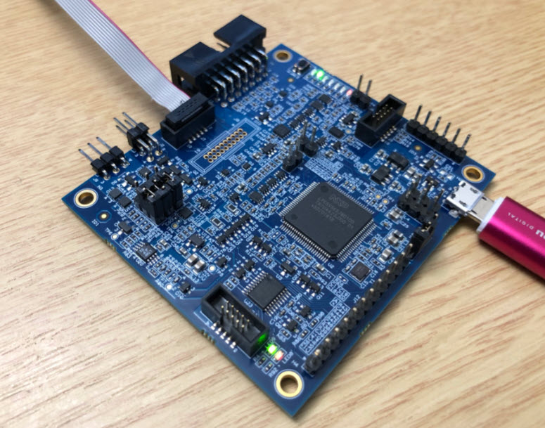
In this article I show how a customized enclosure can be created for it.
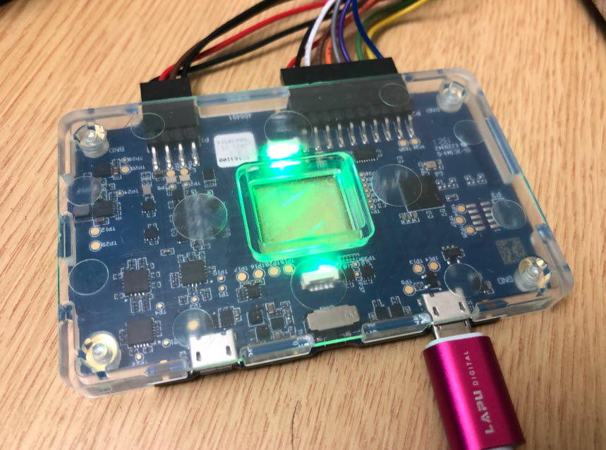
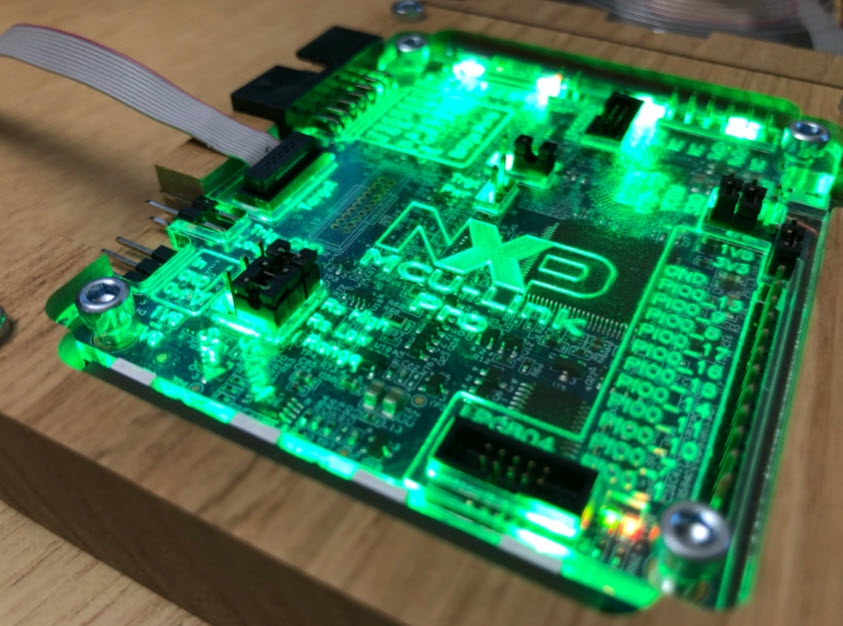
There are several options: From adding a laser-cut acrylic cover with or without LED wings:

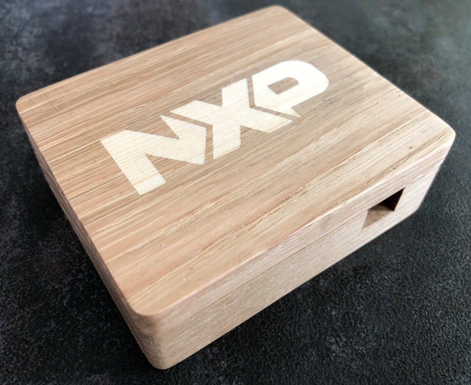
Up to a adding a wood enclosure with a cable compartment and custom inlay logo on the top:


I wanted to have the acrylic cover illuminated with different (RGBW) colors: not only to show status, but as well to make it easier to identify the board headers and connectors. And of because a glowing piece of hardware on my lab desk lets everyone stop walking by ;-).
The acrylics are laser-cut, and the for the wood part a desktop CNC has been used. If you don’t have access to these tools, you should be able to find providers online, or check for a university fab-lab nearby. For the design files, check out the links at the end of this article.
Original Idea
While thinking about how to add an enclosure, I had the . The same time I really like the way Nordic made the Power Profiler Kit II which has a nice transparent enclosure with LED lights indicating the status.
So why not doing something similar for the MCU-Link Pro?
Acrylic Cover
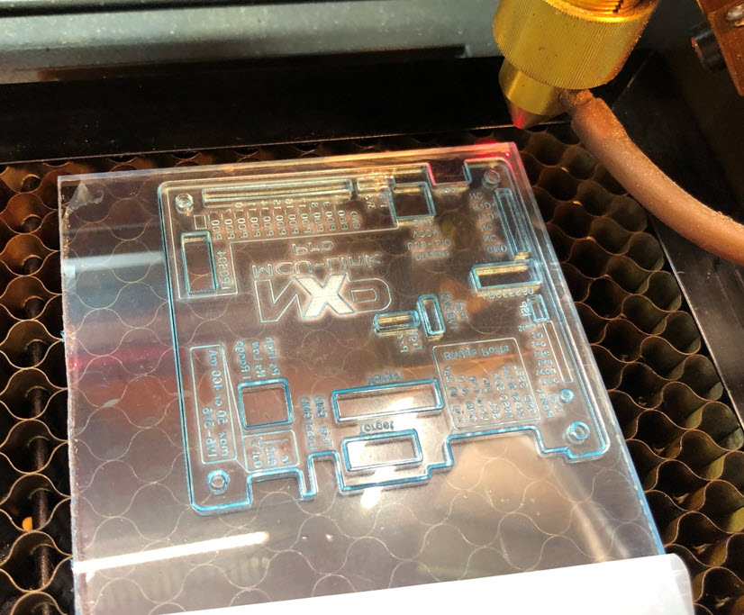
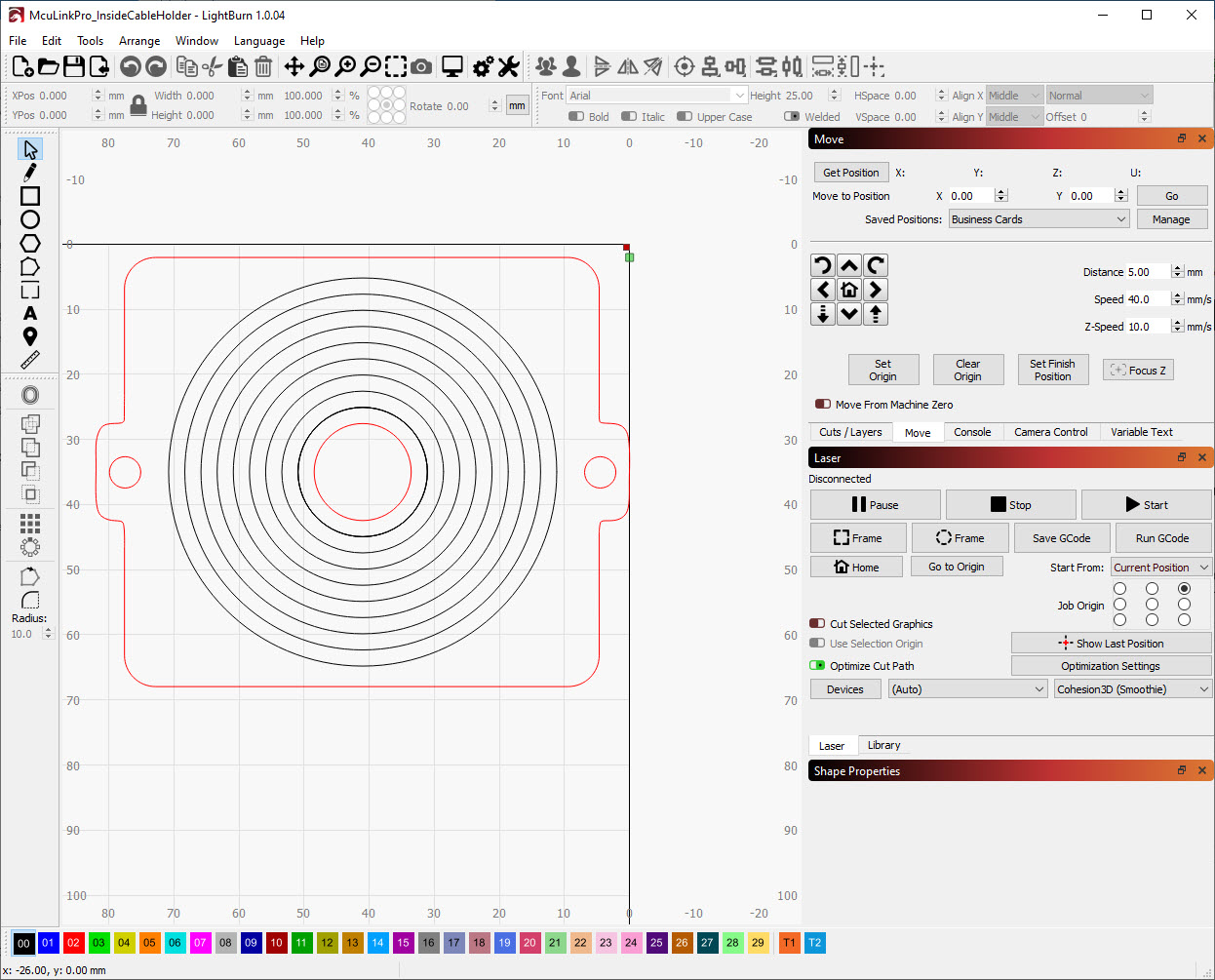
The first step was to create an acrylic cover to protect the electronics, similar to the Nordic Power Profiler II. The design has been created with Inkscape and cut with the Laser and Lightburn:
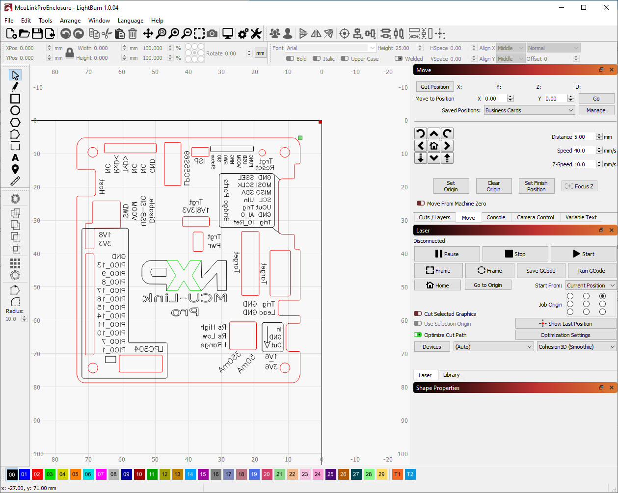
I have used 3 mm PMMA/Acrylic, with the writing engraved on the *bottom* side:
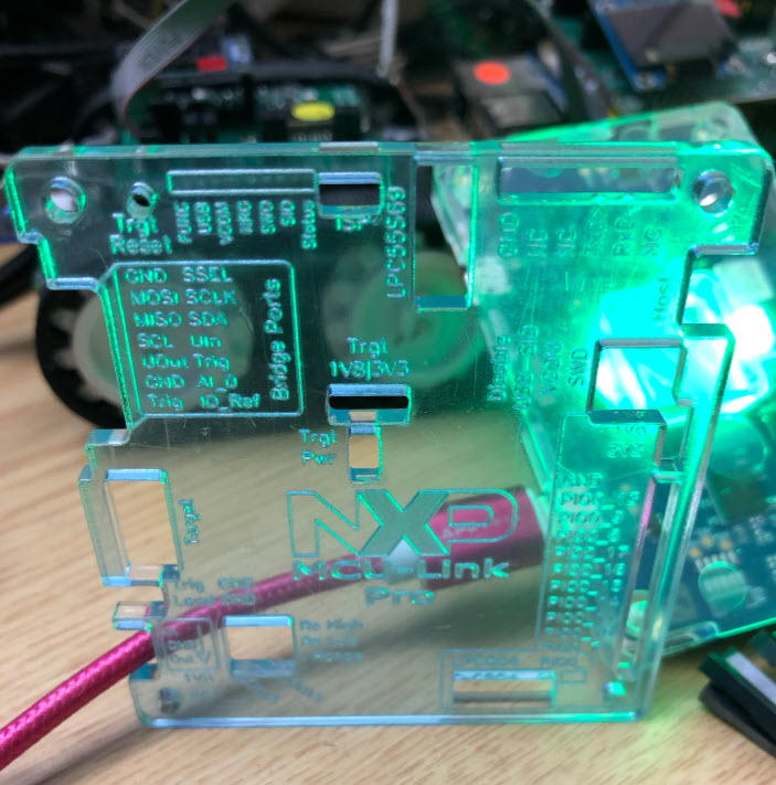
With this I can protect the electronics, and the same time I have a readable documentation about the jumper settings, pins and connectors. Engraving logo/text on the bottom side keeps the top of the acrylic flat, making it easier to clean it from dust/etc.
LEDs: Proof of Concept
The next idea was to make it shine with some RGB(W) LEDs. I thought of using the on-board LPC804 to drive WS2812B LEDs. It started with a proof of concept: using Adafruit NeoPixel PCBs, wires, glue and and lots of taping:
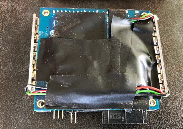
Basically a level shifter, resistor plus the connection wires to between the MCU-Link Pro and the WS2812B:
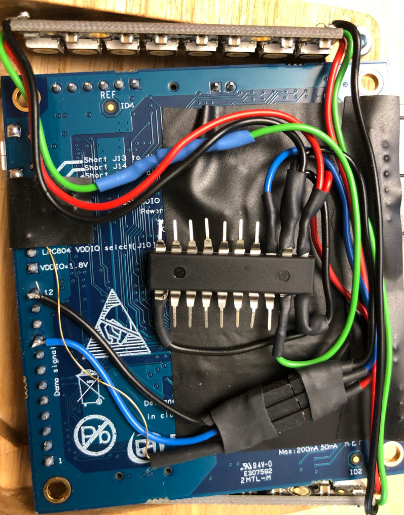
It worked, but was a mess. I had to change it with a custom PCB.
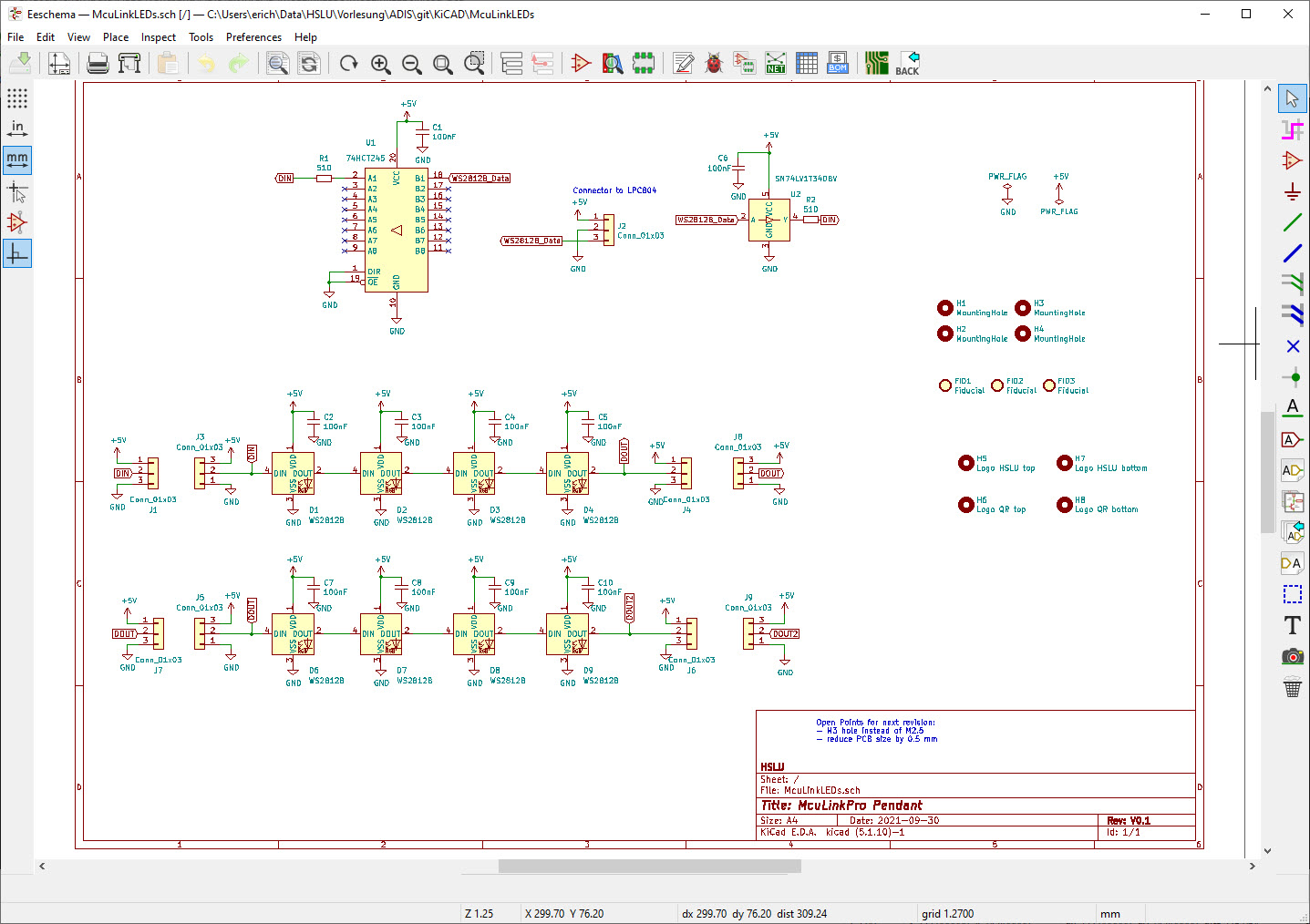
KiCAD & PCB
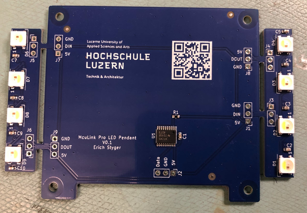
The logical step was to design a PCB with KiCAD: the MCU-Link Pro LED Pendant:
The PCB has ‘wings’ on the side for the WS2812B (SK6812) LEDs:

Below with the SMD parts populated on the board:
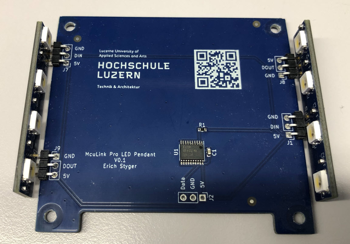
The LED wings then get mounted on the sides of the PCB using standard 2.54 mm angled headers:
LED Pendant Connection
The circuit needs only three things: 5V as power supply for the level shifter and the LEDs, the LED data line (PIO0_8) and GND.
GND and PIO0_8/data are easy: they are available from on the bottom side of the MCU-Link Pro, header J12 of the LPC804:

But the 5V is not available on the bottom side. But it is available from the USB connection on a pin of D1 on the top side:

The solution is to solder a wire on the pin of D1:

The LED Pendant PCB then gets mounted below the MCU-Link Pro PCB using M3 Hex screws and 4 nuts:
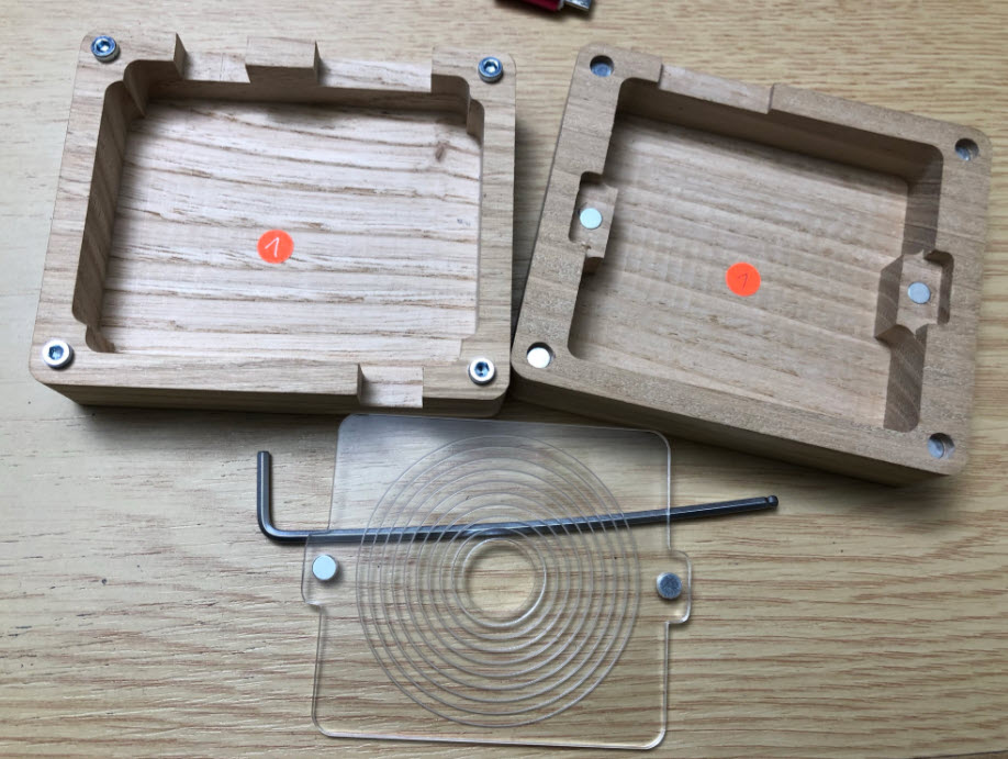
Wood Enclosure
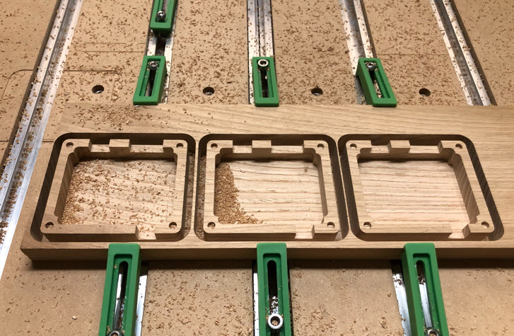
I did design the enclosure top and bottom parts with Carbide Create:

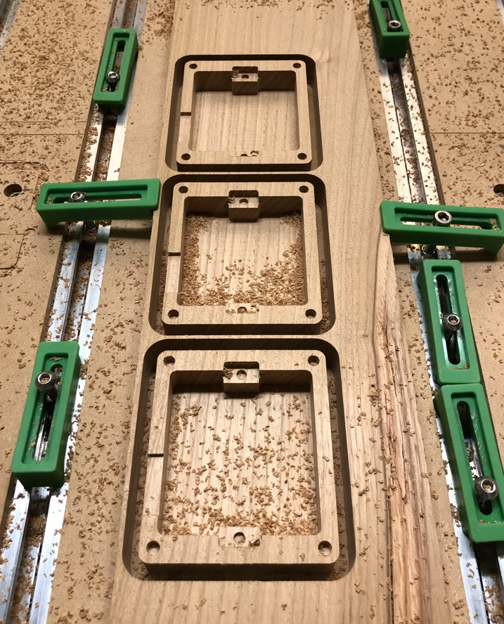
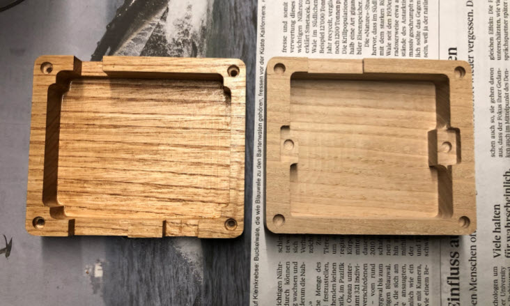
I used 20 mm Elm wood for it. Below three pieces of the bottom parts:
Same for lid/top parts:
Inlay and V-Carving
To create the V-Carving, I’m using the F-Engrave tool: free of charge and an excellent tool for all kind of engraving. I’m using the V1.75 (latest version). I highly recommend to read the documentation first.
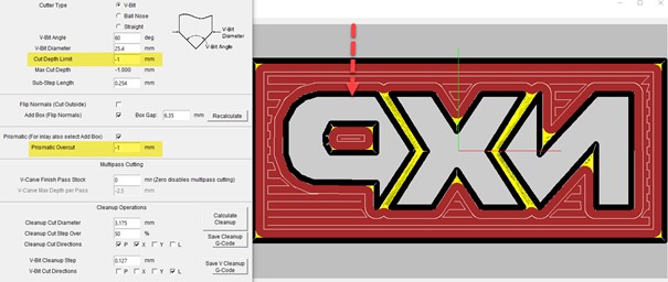
The logo gets loaded as .dxf file, and the pocket cut operation calculated:
I used the following settings:

This creates three G-Code files:
- Pocket_v_carve.ngc
- Pocket_v_carve_clean.ngc
- Pocket_flat_clean.ngc
The first file does a V-Carving with a 60 degree bit, followed by a ‘clean’ pass doing the finer parts. The last file is doing the inner flat areas with a flat 1/8″ (3.175 mm) end-mill.
For the inlay I have to mirror the image and cut a ‘negative’. I used the following settings, tweaked a bit to make a perfect fit:
Here again, the result are three files:
- Inlay_v_carve.ngc
- Inlay_v_clean.ngc
- Inlay_flat_clean.ngc
The first two are with a 60 degree V-Bit, and the last one with a 1/8″ flat end-mill.
I had to tweak the resulting G-Code files, because Carbide Motion does not like standalone feed rates in the file, so I changed them as below:
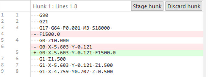
The tool change will be done manually between the files.
V-Carving and Inlays
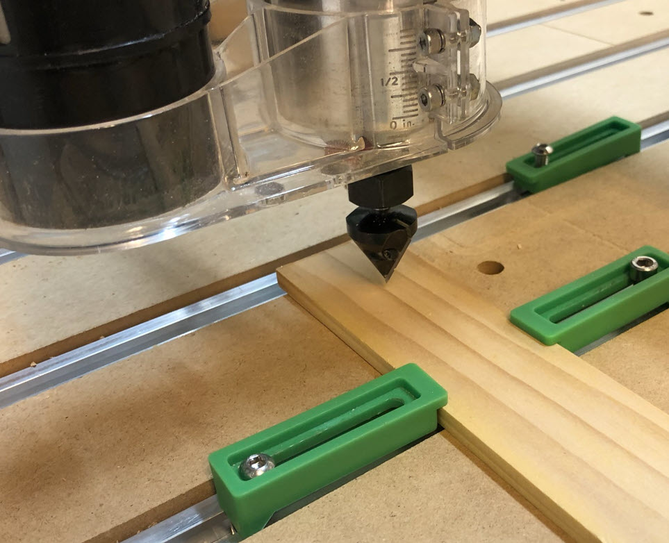
For the V-Carving and inlays I used a 60 degree V-bit:

The top lid gets attached to the desktop CNC:
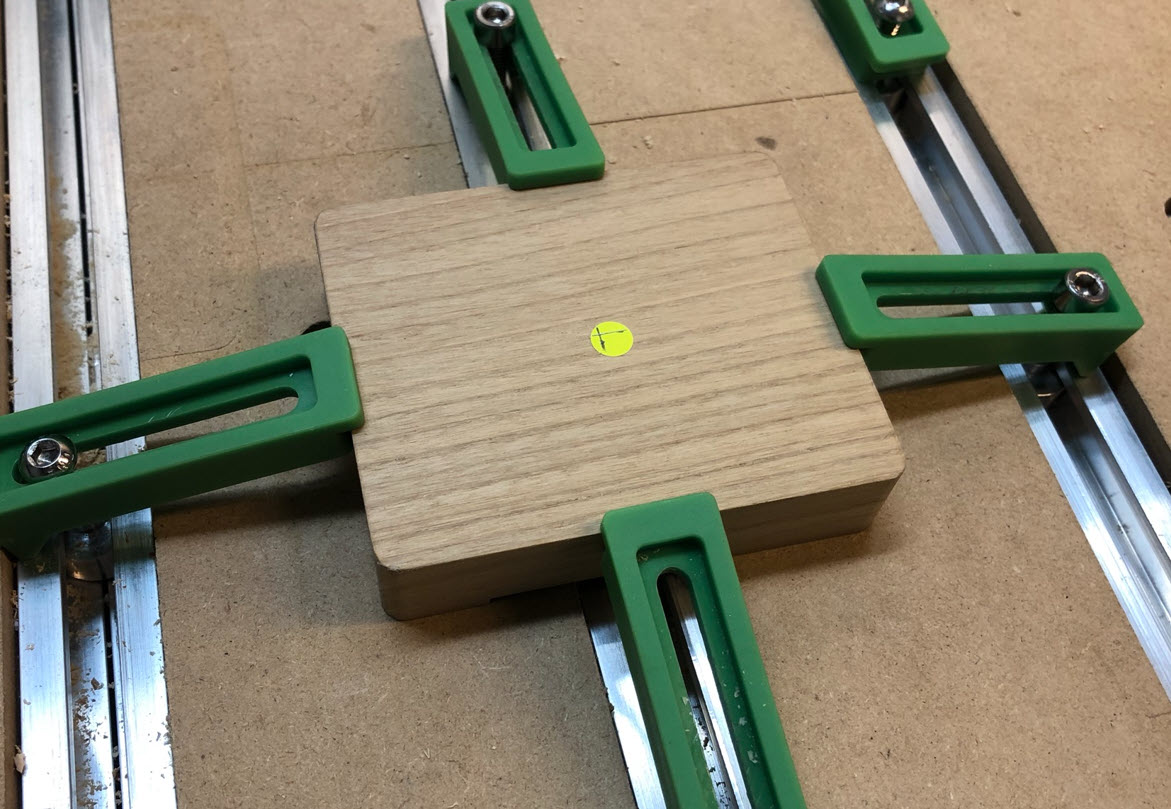
The machine gets centered on the middle of the lid:

The first step is to use the V-Bit:
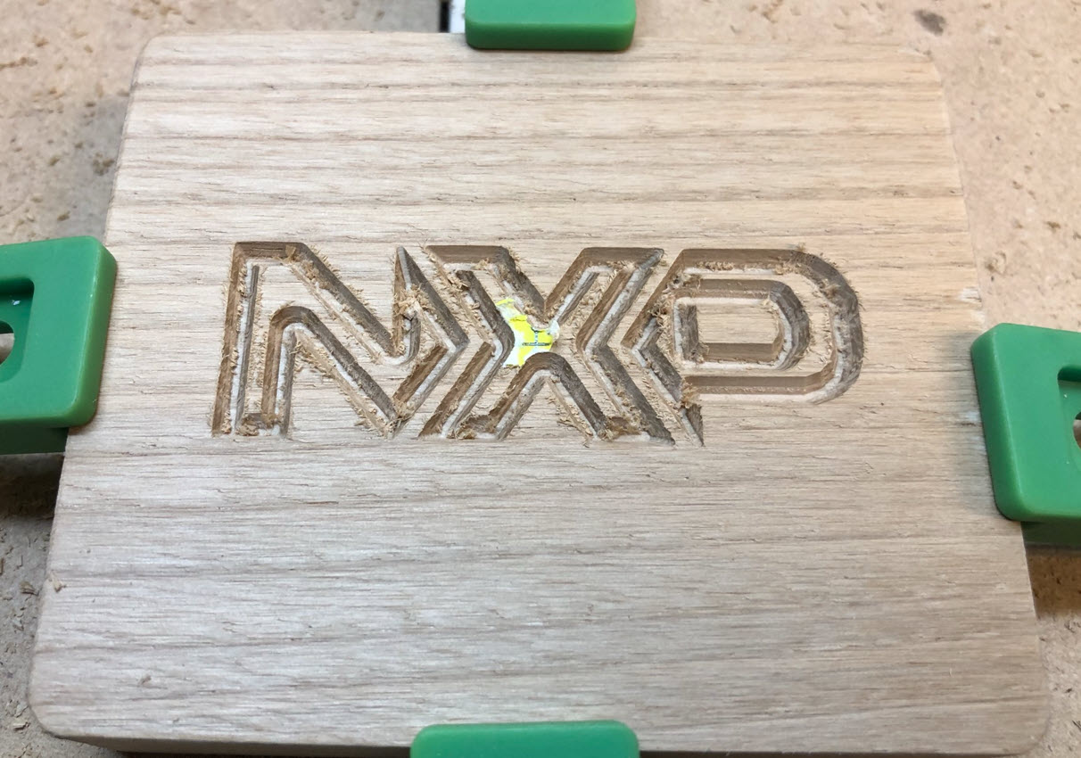
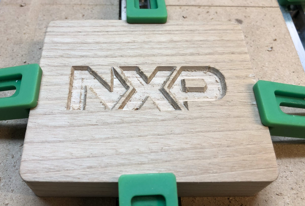
The remainder gets milled out with a flat 1/8″ end-mill:

This cleans the flat parts:
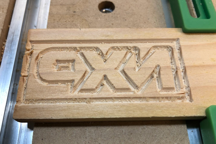
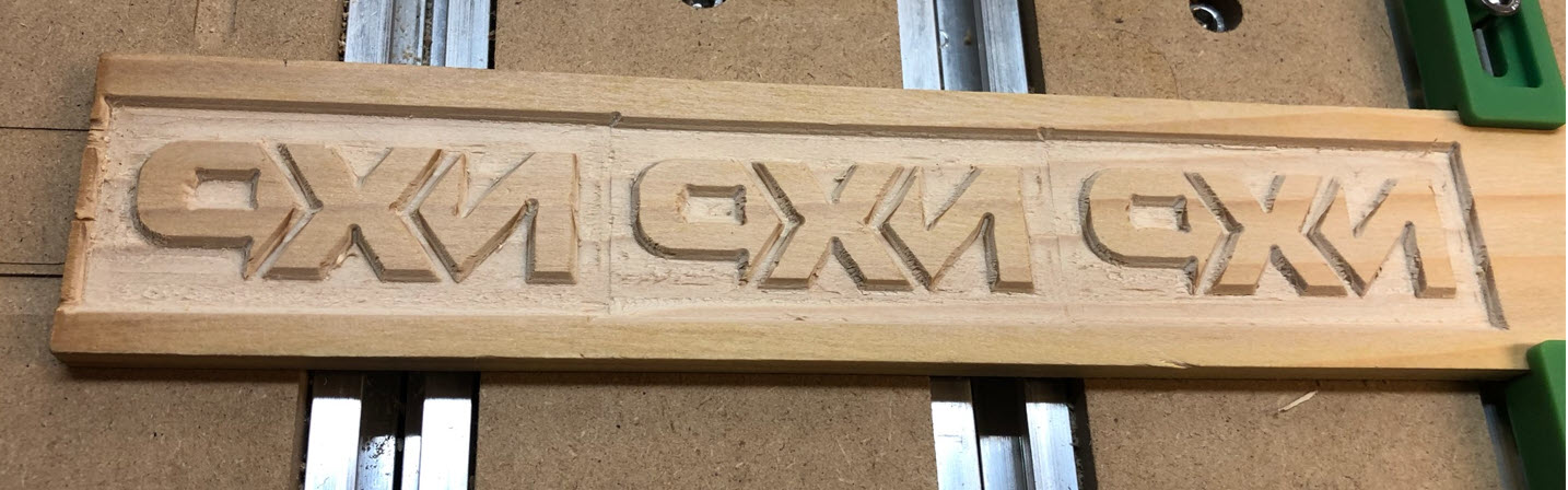
Next, use the V-Bit to mill the inlay, in this case out of pine wood:
Below the first piece after v-carving:
And here with the flat parts cleaned using the flat end-mill:
The border around them can be removed:

Gluing
Below the pocket and inlay together:
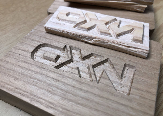
They both get now glued together:
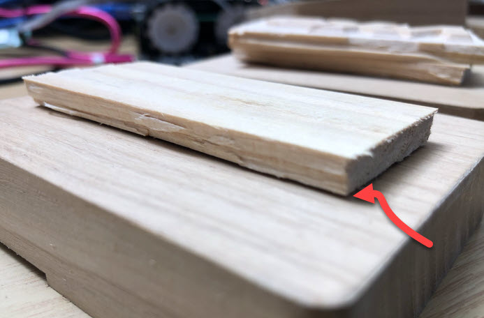
The two pieces must tie together, only with a 1 mm gap between them:
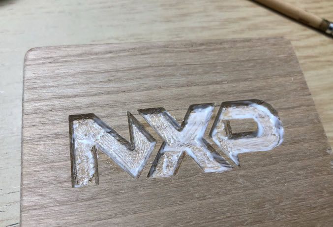
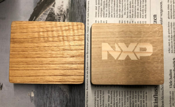
The next day, the wood can be cut down and then sanded:

It gets sanded down, until the logo is flat with the surrounding wood:

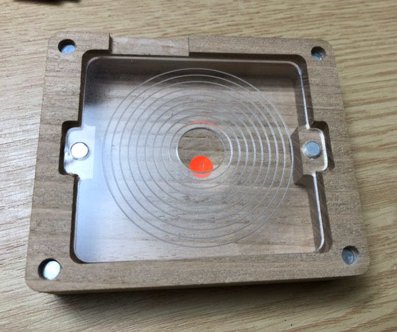
Hex Screws and Magnets
The bottom part has four holes to place hex screws into it: together with magnets they help to align and secure the bottom with the lid:

I used four press-fit 5x2mm magnets as counter parts in the lid.
The same magnets are used for the cable compartment.
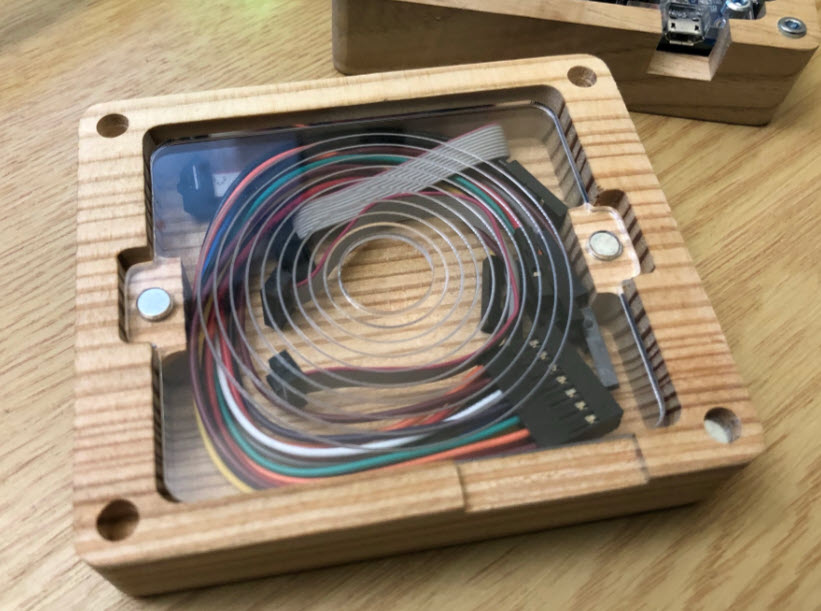
Cable Compartment
The MCU-Link Pro comes with a set of cables and wires, and honestly: I always leave them in the wrong place. So why not having a compartment in the enclosure to store them?
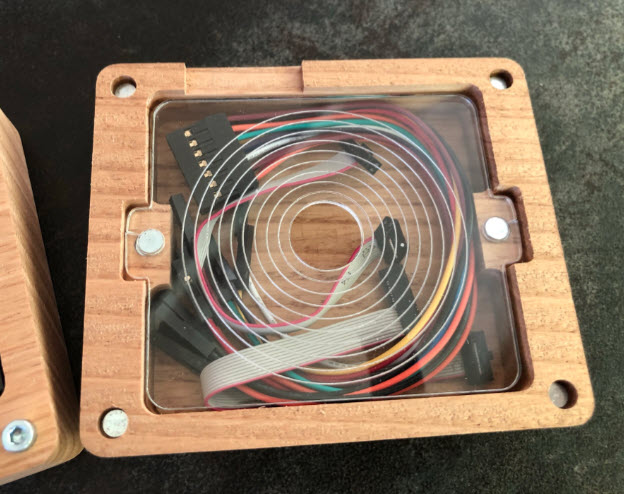
And this is it:
An engraved and laser-cut PMMA sheet, which is hold back by magnets, which securely stores all the cables in the upper compartment of the enclosure.
The enclosure below is using an ‘Alpine Pinus Cembra’ wood. I produced a total of 5 enclosures.
Wood Oil
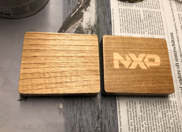
Finally, the wood gets a treatment with a wood oil.

The picture below shows the effect: it not only protects the surface, it augments the wood structure.


Compact Version
I did create as well a ‘compact’ version: the lid does not include the cable compartment:

That version is 10 mm less in height, but does not allow to store the cables inside. Overall, I find the one with the cable compartment more useful.
Software
The software to drive the LEDs on the pendant is written with the NXP MCUXpresso IDE, and it is available on GitHub. It runs FreeRTOS with the McuLib and the MCUXpresso SDK.

The MCU-Link Pro debug probe can be used to debug the LPC804 on the board.

To drive the WS2812B/SK6812 LEDs, the PLU of the LPC804 is used. The PLU has been configured with a special PLU Configuration tool from NXP:
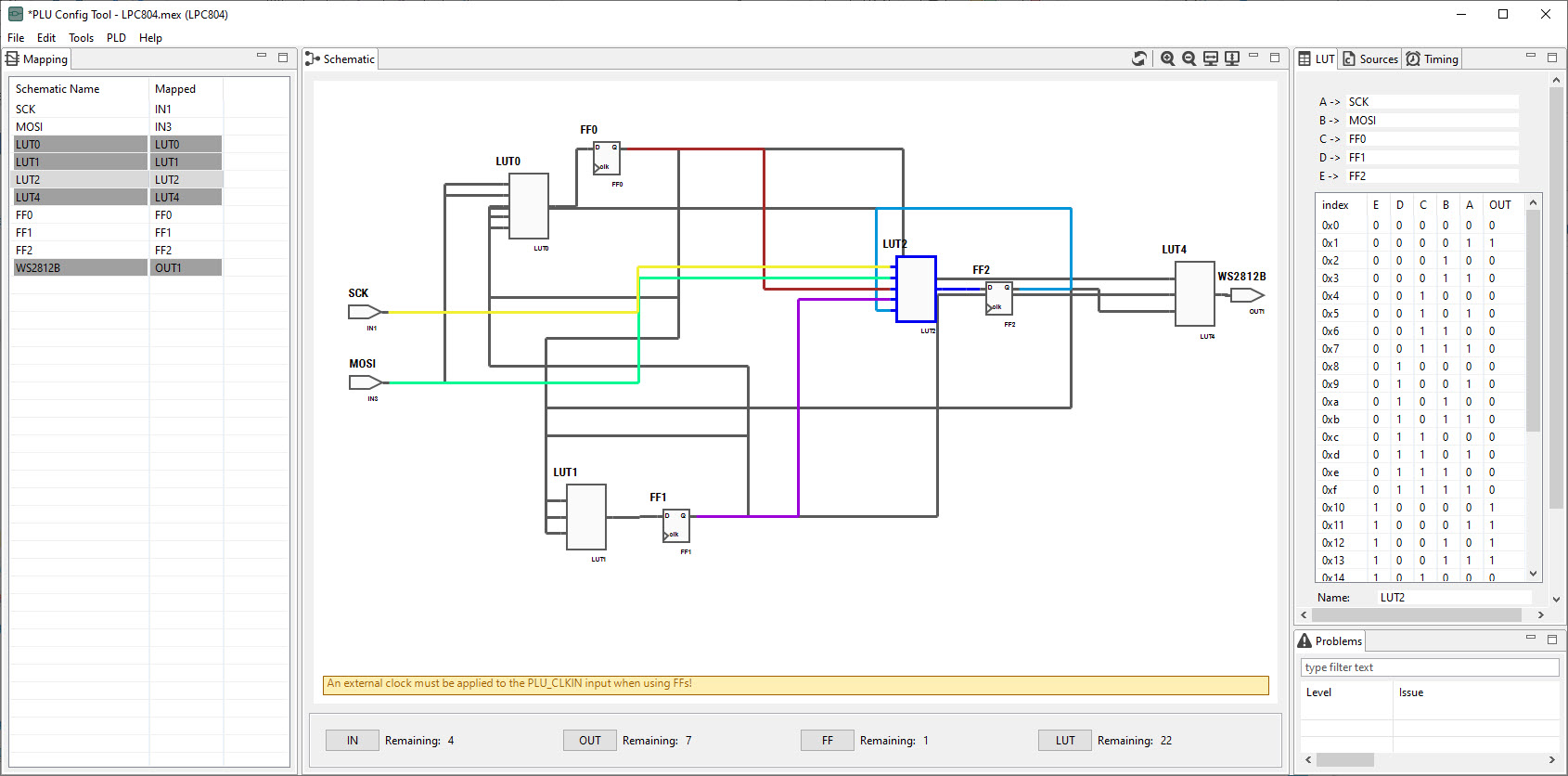
The generated code then has been added to the project and integrated with the NXP MCUXpresso SDK.

The number of WS2812B/SK6812/Neopixels can be configured, including gamma correction:
The transfer of the pixel data is done though SPI writes which then gets transformed by the PLU into the necessary waveform:
The software project can be found on GitHub.
Result
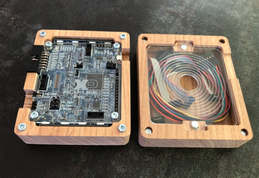
The MCU-Link Pro PCB with the LED Pendant/wings fits into the lower part of the enclosure.

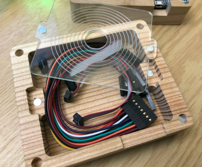
The cables are stored behind the acrylic cover inside the lid.
The RGBW LEDs nicely illuminate the acrylic cover:
Summary
I have produced 5 enclosures so far, and having material to produce 5 more (I did order 10 PCBs). And I’m going to use the MCU-Link Pro in my low-power class because of its debug and power measurement capabilities. For the labs I need to add an enclosure anyway to have the PCB protected, otherwise I fear damage by ESD.
It takes work and time to build such an enclosure, because of the many manual steps (soldering, sanding, …) involved. Yes, an overkill just to have an enclosure, but the result is very pleasing: I find it aesthetic and functional the same time: the enclosure adds protection, stores the cables away. I can use the LPC804 on the MCU-Link Pro to control the test farm equipment, and with the RGBW LEDs it nicely shows the progress and current status. Beside of making it look really cool, if only used as a normal debug and power measurement probe.
Happy modding 🙂
Links
- NXP MCU Link Debug probe: New “MCU-Link Pro”: Debug Probe with Energy Measurement
- F-Engrave by ScorchWorks: https://www.scorchworks.com/Fengrave/fengrave_doc.html
- Carbide Motion: https://carbide3d.com/carbidemotion/
- Software/Project on GitHub: https://github.com/ErichStyger/mcuoneclipse/tree/master/Examples/MCUXpresso/LPC804/LPC804_Blinky
- Design Files on GitHub: https://github.com/ErichStyger/mcuoneclipse/tree/master/MCU-Link/Pro
- CNC Files on CutRocket: https://cutrocket.com/p/60ebec7c156f3/
- Oli Kraus, PLU Tutorials: https://github.com/olikraus/lpc804_plu

Wonderful! I mean its absolutely awesome! Overkill yes, but it looks so cool!
LikeLiked by 1 person
Yes, for sure an overkill. It is gorgeous. I have observed people walking by at my desk, staring at it for minutes. And it makes debugging so more enjoyable:-)
LikeLiked by 1 person
Very nice Erich! But from just reading this I am exhausted, so now I must go take a nap…
LikeLiked by 2 people
Thanks! And have a good nap 🙂
LikeLike
Good day Erich,
Wow, you did an amazing job! Also, just a heads up that you can get pixel LEDs in a side mounted and smaller version that would work nicely for illuminating acrylic covers. You can find these leds at the usual sites, but below provides some good pictures and details:
https://www.aliexpress.com/item/1005002979621739.html
I only recently found these and so I have yet to use them for a project… and so I cannot comment how well they work. I was planning on using them in a similar fashion to what you did.
Cheers,
Sam
LikeLiked by 1 person
Hi Sam,
Thanks!
yes, I’m using the SK6812-SIDE in many of my projects, for example https://mcuoneclipse.com/2020/05/24/60-billion-lights-2400-rgb-leds-and-120-stepper-motors-hiding-behind-canvas-art/ , https://mcuoneclipse.com/2020/12/26/new-metaclockclock-v3-finished-with-60-clocks/ or https://mcuoneclipse.com/2021/07/11/round-metaclockclock/
They work very well, but reflow soldering is a bit of challenge. After a while, I have the process under control now :-).
But I did not use them for this project because anyway I had to raise the LEDs from the bottom up to the acrylic: using side LEDs would not helped in my case, the ‘normal’ ones are just fine for this application. I did consider using smaller footprints/LEDs, but here again: that would not have made much of a difference.
Erich
LikeLike
Good day Erich,
Understood. With regards to reflowing these and other similar components…On my side the best thing I did was to invest in a smaller commercial reflow oven. Prior to this I used some inexpensive ovens and even a few converted toaster ovens. All of this would do the job, but had issues with the reflow and/or would overheat/discolor some components. All of these issues disappeared when I bought a commercial grade oven. I simply select the profile I need (I have a couple based upon the paste I am using, etc) and let the machine do the work and so far all of my boards (probably close to a 1000 now) come our perfectly. If you are not using a commercial oven I would highly recommend you invest in one, as it can save you a lot of time along with having excellent results.
Cheers, Sam
LikeLike
Recommend an oven Sam?
LikeLike
Hi Sam,
actually we have a huge and professional reflow oven with different temperature zones :-). The issue is more about the pads and placements of these SK6812-SIDE LEDs: the PnP (Pick&Place) machine needs to be highly accurate and tuned, otherwise the LEDs might not be soldered properly. Additionally the amount of solder for these parts is somewhat critical. At the beginning I had to re-work about 2-3%, now it is below 0.1%, so good enough.
LikeLike
I’ve used light-pipes with normal surface-mount LEDs, another option to avoid multiple boards/connections. Of course that only works if you can find a common pipe with the dimensions you need, but they’re available in lots of shapes and sizes: https://www.digikey.com/en/products/filter/optics-light-pipes/102?s=N4IgTCBcDaIA4Es4FMDOIC6AaEBWKocUYOcRkYuAvlUA
Thanks Erich!
LikeLiked by 1 person
Yes, I did check some light pipes (thanks for that extra link!), but have not found any suitable. At the end it was simpler to add these wing boards: less expensive, easier to mount and handle. Thanks again for the link!
LikeLike