The Espressif ESP32 devices are getting everywhere: they are inexpensive, readily available and Espressif IDF environment and build system actually is pretty good and working well for me including Eclipse (see “Building and Flashing ESP32 Applications with Eclipse“). The default way to program an ESP32 is to a) enter UART bootloader by pressing some push buttons and b) flash the application with ESP-IDF using a USB cable.
That works fine if the ESP32 is directly connected to the host PC. But in my case it is is behind an NXP Kinetis K22FX512 ARM Cortex-M4F microcontroller and not directly accessible by the host PC. So I had to find a way how to allow boot loading the ESP32 through the ARM Cortex-M which is the topic of this article.

TTGO ESP32 MICRO-D4 Module
The reason for this setup is the new lecture and lab material we are building for the ‘Advanced Distributed Systems’ class at the Lucerne University. The ESP32 Wi-Fi (and BLE) module is operated by the main robot processor (NXP Kinetis K22FX512, to be replaced by a NXP Kinetis K22FN512 in a next board revision).
The picture below shows a bench setup with hardware and analyzers:

test setup
ESP32 Module
I have selected the TTGO TTGO Micro-32 module because it is inexpensive, lots of tutorials and documentation available and it is much smaller than the usual ESP32.
Below a comparison of the ‘normal’ ESP32 module and the Micro-32 with the ESP32 PICO-D4 one:

TTGO Micro-32 with a normal ESP32 module
The above boards include the UART-2-USB CDC interface on the left side which is used for programming the devices. There are two push buttons: EN/Reset (low active) and the boot selection switch (IO0).
Below the pinout of the module which is available on GitHub:

TTGO ESP32
For the first steps a module was soldered on a pin socket and then used with a bread board:

TTGO ESP32 Breakout board
To use the module, only a few pins are needed:
- GND and 3.3V
- EN which is a reset (low active)
- IO0 (low active) which is used to put the module into serial bootloader mode during reset
- UART Tx and Rx for serial connection and serial bootloader
The next step was to build a first prototype board as a shield on top of the robot:

V1.0 Schematics

Robot with V1.0 of the TTGO Shield
Because the 3.3V DC-DC converter of the robot was not able to provide the needed mA in all modes, an extra DC-DC converter from 5V has been added. Something else which is missing in that version is a 100 nF between GND and EN signal. A new version of the PCB with other changes is currently getting produced.
Programming the Module
The main processor on the robot is the NXP K22FX512. Software has been developed with the Eclipse based MCUXpresso IDE and the MCUXpresso SDK.

Sumo Project
The idea is that the K22 acts as a gateway between the host PC and the ESP32.

Connection Diagram
To enter the bootloader mode of the ESP, the IO0 signal needs to be kept low while releasing the reset line. The typical ESP32 boards come with a UART-2-USB converter and the toggling of the EN and IO0 is done with using USB CDC with flow control signals (RTS and CTS in the classic RS-232 world). So basically on the K22 I have to run a USB CDC stack and properly handle the flow control signals.
A command line shell on the robot provides a direct access to the ESP32 module:

ESP32 shell commands

ESP32 status command
USB CDC
There is a basic USB CDC example project in the NXP MCUXpresso SDK. But it only works for very simple case and is not reentrant. That problem was not that easy to find: basically using a terminal with flow control enabled the USB stack did not send back the ACK packages, causing the terminal on the host to block. Very helpful to identify the issue was using a LeCroy USB analyzer:

LeCroy USB Protocol Analyzer
The first thing to change is to use an reentrant ring buffer for the received data in the virtual_com.c, and to schedule a next receive event. The changes are marked below with ‘<< EST’.
        case kUSB_DeviceCdcEventRecvResponse:
        {
            if ((1 == s_cdcVcom.attach) && (1 == s_cdcVcom.startTransactions))
            {
#if 1 /* << EST */ size_t i, dataSize; dataSize = epCbParam->length;
                if (dataSize!=0 && dataSize!=(size_t)-1) {
                  i = 0;
                  while(i<dataSize) { McuRB_Put(usb_rxBuf, &s_currRecvBuf[i]); i++; } } #endif #if defined(FSL_FEATURE_USB_KHCI_KEEP_ALIVE_ENABLED) && (FSL_FEATURE_USB_KHCI_KEEP_ALIVE_ENABLED > 0U) && \
    defined(USB_DEVICE_CONFIG_KEEP_ALIVE_MODE) && (USB_DEVICE_CONFIG_KEEP_ALIVE_MODE > 0U) &&             \
    defined(FSL_FEATURE_USB_KHCI_USB_RAM) && (FSL_FEATURE_USB_KHCI_USB_RAM > 0U)
                s_waitForDataReceive = 0;
                USB0->INTEN |= USB_INTEN_SOFTOKEN_MASK;
#endif
                //if (!s_recvSize) /* << EST */ { /* Schedule buffer for next receive event */ error = USB_DeviceCdcAcmRecv(handle, USB_CDC_VCOM_BULK_OUT_ENDPOINT, s_currRecvBuf, g_UsbDeviceCdcVcomDicEndpoints[0].maxPacketSize); #if defined(FSL_FEATURE_USB_KHCI_KEEP_ALIVE_ENABLED) && (FSL_FEATURE_USB_KHCI_KEEP_ALIVE_ENABLED > 0U) && \
    defined(USB_DEVICE_CONFIG_KEEP_ALIVE_MODE) && (USB_DEVICE_CONFIG_KEEP_ALIVE_MODE > 0U) &&             \
    defined(FSL_FEATURE_USB_KHCI_USB_RAM) && (FSL_FEATURE_USB_KHCI_USB_RAM > 0U)
                    s_waitForDataReceive = 1;
                    USB0->INTEN &= ~USB_INTEN_SOFTOKEN_MASK;
#endif
                }
            }
        }
        break;
The next thing was to properly handle the kUSB_DeviceCdcEventSetControlLineState and to call the application callback:
        case kUSB_DeviceCdcEventSetControlLineState:
        {
            s_usbCdcAcmInfo.dteStatus = acmReqParam->setupValue;
            /* activate/deactivate Tx carrier */
            if (acmInfo->dteStatus & USB_DEVICE_CDC_CONTROL_SIG_BITMAP_CARRIER_ACTIVATION)
            {
                acmInfo->uartState |= USB_DEVICE_CDC_UART_STATE_TX_CARRIER;
            }
            else
            {
                acmInfo->uartState &= (uint16_t)~USB_DEVICE_CDC_UART_STATE_TX_CARRIER;
            }

            /* activate carrier and DTE. Com port of terminal tool running on PC is open now */
            if (acmInfo->dteStatus & USB_DEVICE_CDC_CONTROL_SIG_BITMAP_DTE_PRESENCE)
            {
                acmInfo->uartState |= USB_DEVICE_CDC_UART_STATE_RX_CARRIER;
           }
            /* Com port of terminal tool running on PC is closed now */
            else
            {
                acmInfo->uartState &= (uint16_t)~USB_DEVICE_CDC_UART_STATE_RX_CARRIER;
            }
            /* Indicates to DCE if DTE is present or not */
            acmInfo->dtePresent = (acmInfo->dteStatus & USB_DEVICE_CDC_CONTROL_SIG_BITMAP_DTE_PRESENCE) ? true : false;
    #if 1 /* << EST */ // http://markdingst.blogspot.com/2014/06/implementing-usb-communication-device.html // bit 0: Indicates to DCE if DTE is present or not. This signal corresponds to V.24 signal 108/2 and RS232 signal DTR. // 0: DTE is not present. // 1: DTE is present // bit 1: Carrier control for half duplex modems. This signal corresponds to V.24 signal 105 and RS232 signal RTS. // 0: Deactivate carrier. // 1: Activate carrier. // The device ignores the value of this bit when operating in full duplex mode. McuESP32_UartState_Callback(acmInfo->uartState);
        #if ENABLED_USB_CDC_LOGGING
            McuRTT_printf(0, "CDC: set control dteStatus: %d, uartState: %d, dtePresent: %d, attach: %d, startTransaction: %d\r\n", s_usbCdcAcmInfo.dteStatus, acmInfo->uartState, acmInfo->dtePresent, s_cdcVcom.attach, s_cdcVcom.startTransactions);
        #endif
    #endif

            /* Initialize the serial state buffer */
            acmInfo->serialStateBuf[0] = NOTIF_REQUEST_TYPE;                /* bmRequestType */
            acmInfo->serialStateBuf[1] = USB_DEVICE_CDC_NOTIF_SERIAL_STATE; /* bNotification */
            acmInfo->serialStateBuf[2] = 0x00;                              /* wValue */
            acmInfo->serialStateBuf[3] = 0x00;
            acmInfo->serialStateBuf[4] = 0x00; /* wIndex */
            acmInfo->serialStateBuf[5] = 0x00;
            acmInfo->serialStateBuf[6] = UART_BITMAP_SIZE; /* wLength */
            acmInfo->serialStateBuf[7] = 0x00;
            /* Notify to host the line state */
            acmInfo->serialStateBuf[4] = acmReqParam->interfaceIndex;
            /* Lower byte of UART BITMAP */
            uartBitmap = (uint8_t *)&acmInfo->serialStateBuf[NOTIF_PACKET_SIZE + UART_BITMAP_SIZE - 2];
            uartBitmap[0] = acmInfo->uartState & 0xFFu;
            uartBitmap[1] = (acmInfo->uartState >> 8) & 0xFFu;
            len = (uint32_t)(NOTIF_PACKET_SIZE + UART_BITMAP_SIZE);
            if (0 == ((usb_device_cdc_acm_struct_t *)handle)->hasSentState)
            {
                error = USB_DeviceCdcAcmSend(handle, USB_CDC_VCOM_INTERRUPT_IN_ENDPOINT, acmInfo->serialStateBuf, len);
                if (kStatus_USB_Success != error)
                {
                  usb_echo("kUSB_DeviceCdcEventSetControlLineState error!");
                }
                ((usb_device_cdc_acm_struct_t *)handle)->hasSentState = 1;
            }

            /* Update status */
            if (acmInfo->dteStatus & USB_DEVICE_CDC_CONTROL_SIG_BITMAP_CARRIER_ACTIVATION)
            {
                /*  To do: CARRIER_ACTIVATED */
#if ENABLED_USB_CDC_LOGGING
              McuRTT_printf(0, "CARRIER_ACTIVATED\r\n");
#endif
            }
            else
            {
                /* To do: CARRIER_DEACTIVATED */
#if ENABLED_USB_CDC_LOGGING
              McuRTT_printf(0, "CARRIER_DEACTIVATED\r\n");
#endif
            }
#if 0
            if (acmInfo->dteStatus & USB_DEVICE_CDC_CONTROL_SIG_BITMAP_DTE_PRESENCE)
#else /* << EST */ if ( (acmInfo->dteStatus & USB_DEVICE_CDC_CONTROL_SIG_BITMAP_DTE_PRESENCE)
                || (s_cdcVcom.attach && (acmInfo->dteStatus==USB_DEVICE_CDC_CONTROL_SIG_BITMAP_CARRIER_ACTIVATION) /* && !s_cdcVcom.startTransactions*/) /* << EST */ ) #endif { /* DTE_ACTIVATED */ if (1 == s_cdcVcom.attach) { s_cdcVcom.startTransactions = 1; #if ENABLED_USB_CDC_LOGGING McuRTT_printf(0, "startTransactions=1\r\n"); #endif #if defined(FSL_FEATURE_USB_KHCI_KEEP_ALIVE_ENABLED) && (FSL_FEATURE_USB_KHCI_KEEP_ALIVE_ENABLED > 0U) && \
    defined(USB_DEVICE_CONFIG_KEEP_ALIVE_MODE) && (USB_DEVICE_CONFIG_KEEP_ALIVE_MODE > 0U) &&             \
    defined(FSL_FEATURE_USB_KHCI_USB_RAM) && (FSL_FEATURE_USB_KHCI_USB_RAM > 0U)
                    s_waitForDataReceive = 1;
                    USB0->INTEN &= ~USB_INTEN_SOFTOKEN_MASK;
                    s_comOpen = 1;
                    usb_echo("USB_APP_CDC_DTE_ACTIVATED\r\n");
#endif
                }
            }
            else
            {
                /* DTE_DEACTIVATED */
                if (1 == s_cdcVcom.attach)
                {
              //      s_cdcVcom.startTransactions = 0;
#if ENABLED_USB_CDC_LOGGING
                   McuRTT_printf(0, "startTransactions=0\r\n");
#endif
                }
            }
        }
        break;
Helper routines deal with the GPIO pin toggling:
static void AssertReset(void) {
  McuGPIO_SetAsOutput(McuESP32_RF_EN_Pin, false); /* output, LOW */
}

static void DeassertReset(void) {
  McuGPIO_SetAsInput(McuESP32_RF_EN_Pin);
}

static void DoReset(void) {
  AssertReset();
  vTaskDelay(pdMS_TO_TICKS(1));
  DeassertReset();
}

static void AssertBootloaderMode(void) {
  McuGPIO_SetAsOutput(McuESP32_RF_IO0_Pin, false); /* output, LOW */
}

static void DeassertBootloaderMode(void) {
  McuGPIO_SetAsInput(McuESP32_RF_IO0_Pin);
}
Now about the control state sequence. I have verified it with different terminal programs and as well how the ESP-IDF is using the DTR/RTS signals during connection, programming and reset at the end:
/* idf.py flash sequence:
 *
 * 00> State: 3, DtrRts: 3

 * 00> State: 2, DtrRts: 1
 * 00> State: 3, DtrRts: 3
 * 00> State: 1, DtrRts: 2
 * 00> State: 0, DtrRts: 0

 * 00> State: 2, DtrRts: 1
 * 00> State: 3, DtrRts: 3
 * 00> State: 1, DtrRts: 2
 * 00> State: 0, DtrRts: 0
 *
 * reset at the end:
 * 00> State: 2, DtrRts: 1
 * 00> State: 0, DtrRts: 0
 */
The ‘magic’ is done in the callback itself: it remembers the previous state of the control line signals and automatically switches to programming mode and back to normal mode:
void McuESP32_UartState_Callback(uint8_t state) { /* callback for DTR and RTS lines */
  static uint8_t prevState = -1;
  static uint8_t prevPrevState = -1;
  uint8_t DtrRts;

#if McuESP32_VERBOSE_CONTROL_SIGNALS
  McuRTT_printf(0, "state: %d, prev: %d, prevprev: %d\r\n", state, prevState, prevPrevState);
#endif
  if (state != prevState) {
    if (McuESP32_UsbPrgMode==McuESP32_USB_PRG_MODE_AUTO || McuESP32_UsbPrgMode==McuESP32_USB_PRG_MODE_ON) {
      /*
       * DTR  RTS  EN  GPIO0
       * 1    1    1   1
       * 0    0    1   1
       * 1    0    0   0
       * 0    1    1   0
       */
      DtrRts = 0;
      if ((state&1)==1) { /* DTR */
        DtrRts |= 2; /* DTR set */
      }
      if ((state&2)==2) { /* DTR */
        DtrRts |= 1; /* RTS set */
      }
    #if McuESP32_VERBOSE_CONTROL_SIGNALS
      McuRTT_printf(0, "State: %d, DtrRts: %d\r\n", state, DtrRts);
    #endif
      switch(DtrRts) {
        default:
        case 0:
          DeassertReset();
          McuWait_Waitus(100); /* block for a short time (in the ISR!!!) ==> should have a 100 uF added to the reset line */
          DeassertBootloaderMode();
          //McuRTT_printf(0, "Release both: %d\r\n", DtrRts);
          break;
        case 1:
          AssertBootloaderMode();
          //McuRTT_printf(0, "assert BL: %d\r\n", DtrRts);
          break;
        case 2:
          if (McuGPIO_IsLow(McuESP32_RF_EN_Pin)) {
            if (McuGPIO_IsLow(McuESP32_RF_IO0_Pin)) {
              McuESP32_IsProgramming = true; /* the DeassertReset() below will enter bootloader mode */
              McuRTT_printf(0, "Enter Bootloader Mode\r\n");
            } else {
              McuESP32_IsProgramming = false; /* the DeassertReset() below will do a reset without bootloader */
              McuRTT_printf(0, "Reset\r\n");
            }
          }
          DeassertReset();
          McuWait_Waitus(100); /* block for a short time (in the ISR!!!) ==> should have a 100 uF added to the reset line */
          //McuRTT_printf(0, "release reset: %d\r\n", DtrRts);
          break;
        case 3:
          AssertReset();
          //McuRTT_printf(0, "assert reset: %d\r\n", DtrRts);
          break;
      } /* switch */
      if (state==0 && prevState==2 && prevPrevState==0) {
        // reset sequence with idf.py and Arduino IDE:
        // State: 0 DtrRts: 0 Release both: 0
        // State: 2 DtrRts: 1 assert BL: 1
        // State: 0 DtrRts: 0 Release both: 0
        McuRTT_printf(0, "Request Reset\r\n");
        McuESP32_ScheduleReset = true; /* cannot do reset sequence here, as called from an interrupt, so we cannot block */
        McuESP32_IsProgramming = false;
      }
    }
    prevPrevState = prevState;
    prevState = state;
  } /* if state!=prevState */
}
UART Tasks
The Tx and Rx to the ESP32 are handled by two simple FreeRTOS tasks on the K22. Below the code on the receiving side:
static void UartRxTask(void *pv) { /* task handling characters sent by the ESP32 module */
  unsigned char ch;
  BaseType_t res;

  for(;;) {
    res = xQueueReceive(uartRxQueue, &ch, portMAX_DELAY);
    if (res==pdPASS) {
#if PL_CONFIG_USE_USB_CDC_ESP32
      if (McuESP32_IsProgramming && USB_CdcIsConnected()) { /* send directly to programmer attached on the USB */
        USB_CdcStdio.stdOut(ch); /* forward to USB CDC and the programmer on the host */
      }
      if (McuESP32_CopyUartToShell && !McuESP32_IsProgramming) { /* only write to shell if not in programming mode. Programming mode might crash RTT */
        SHELL_SendChar(ch); /* write on console output */
      }
#else
    SHELL_SendChar(ch); /* write on console output */
#endif
    }
  }
}
Below the Tx Task code:
static void UartTxTask(void *pv) { /* task handling sending data to the ESP32 module */
  unsigned char ch;
  BaseType_t res;
  bool workToDo;

  for(;;) {
    if (McuESP32_ScheduleReset) {
      McuESP32_ScheduleReset = false;
      McuRTT_printf(0, "Performing reset\r\n");
      DoReset();
    }
    workToDo = false;
    do {
      res = xQueueReceive(uartTxQueue, &ch, 0); /* poll queue */
      if (res==pdPASS) {
        workToDo = true;
        McuESP32_CONFIG_UART_WRITE_BLOCKING(McuESP32_CONFIG_UART_DEVICE, &ch, 1);
      }
    } while (res==pdPASS);
#if PL_CONFIG_USE_USB_CDC_ESP32
    while (USB_CdcStdio.keyPressed()) {
      workToDo = true;
      USB_CdcStdio.stdIn(&ch); /* read byte */
      McuESP32_CONFIG_UART_WRITE_BLOCKING(McuESP32_CONFIG_UART_DEVICE, &ch, 1); /* send to the module */
      if (McuESP32_CopyUartToShell && !McuESP32_IsProgramming) {
        SHELL_SendChar(ch);  /* copy to console */
      }
    }
#endif
    if (!workToDo) {
      vTaskDelay(pdMS_TO_TICKS(5));
    }
  }
}
With this, I can connect to the USB port of the NXPK22 and program the ESP32 with Eclipse:
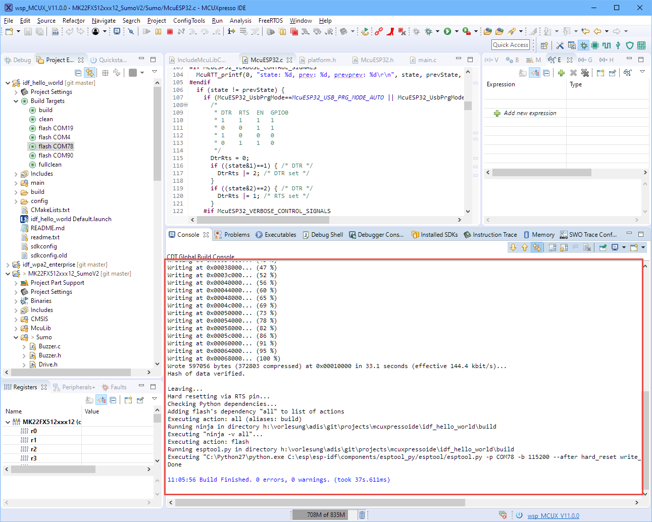
programming ESP32 with Eclipse
Summary
I’m able to use the NXP Kinetis K22 as gateway to the ESP32 module: I can program it and I can use it for a serial/UART/terminal connection. Things have not been optimized yet, so there is currently a limit of 115200 baud as programming speed. Because the idf.py is compressing the image, programming speed is around 150 kBits/s.
Happy ESPing 🙂
Links
- Details about USB CDC Line Coding and Control Line Changes: http://markdingst.blogspot.com/2014/06/implementing-usb-communication-device.html
- LilyGO TTGO GitHub: https://github.com/LilyGO/TTGO-micro32-V2.0
- Building and Flashing ESP32 Applications with Eclipse

Pingback: Eclipse JTAG Debugging the ESP32 with a SEGGER J-Link | MCU on Eclipse
Pingback: JTAG Debugging the ESP32 with FT2232 and OpenOCD | MCU on Eclipse
Pingback: Behind the Canvas: Making of “60 Billion Lights” | MCU on Eclipse