
If you are not aware (yet?): it looks like the COVID pandemic caused a global silicon and microcontroller shortage with lead times >50 weeks in some cases. The microcontroller I have used for the MetaClockClock build (see “New MetaClockClock V3 finished with 60 Clocks” and “MetaClockClock V4 for the Year 2021“) is affected by this too, but I had luck and still enough microcontrollers to build a few more boards.
So I still have enough for building a new variant with it (not finished yet). While everyone else is waiting for the devices to arrive, here are more details and instructions for your own build.
Outline
The ‘MetaClockClock’ project is using multiple small dual-shaft stepper motors which are usually used in instrumentation clusters. In this project multiple such motors are interconnected on a RS-485 bus and can be controlled by a master to display information or show different animation patterns. See “MetaClockClock V4 for the Year 2021“, “New MetaClockClock V3 finished with 60 Clocks” or ““60 Billion Lights”: 2400 RGB LEDs and 120 Stepper Motors hiding behind Canvas Art“.
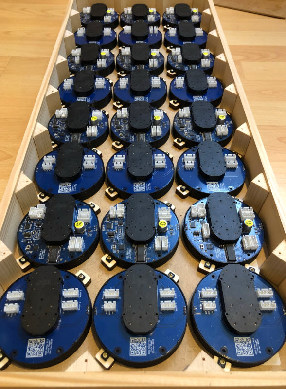
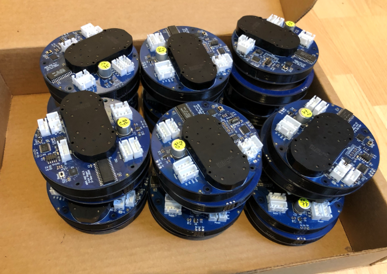
For this build I used a new PCB design: the motors are on round PCBs allowing to mount them in a modular way. Instead having 4 motors on a single PCB as in the previous design, each motor is on its own PCB. That way small tolerances in the enclosure are not a problem and simplify the build. Additionally one is free about changing the distance between the motors.
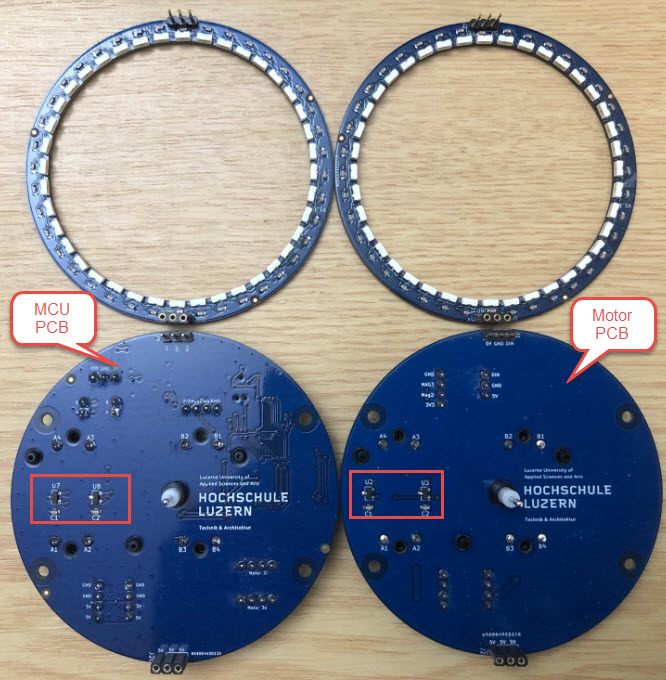
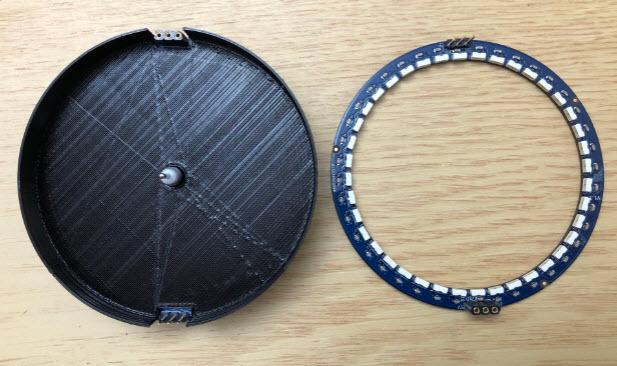
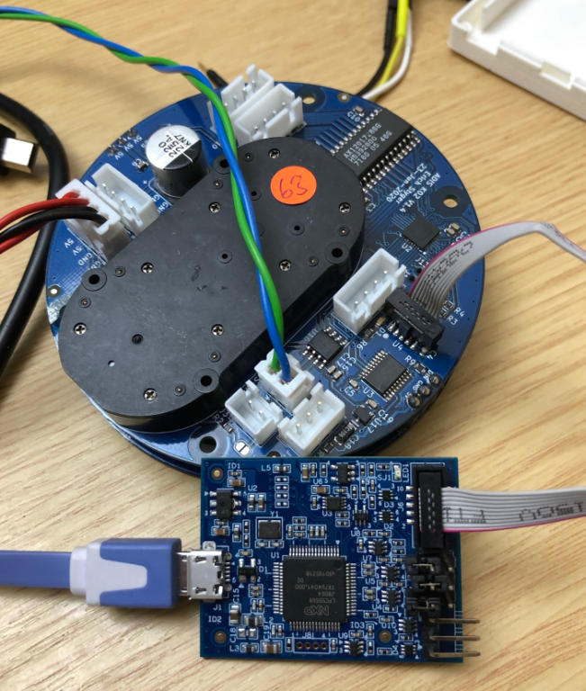
One ‘MCU’ board (left side) can optionally drive one additional ‘satellite’ motor board (right side) which reduces costs but increases wiring efforts:

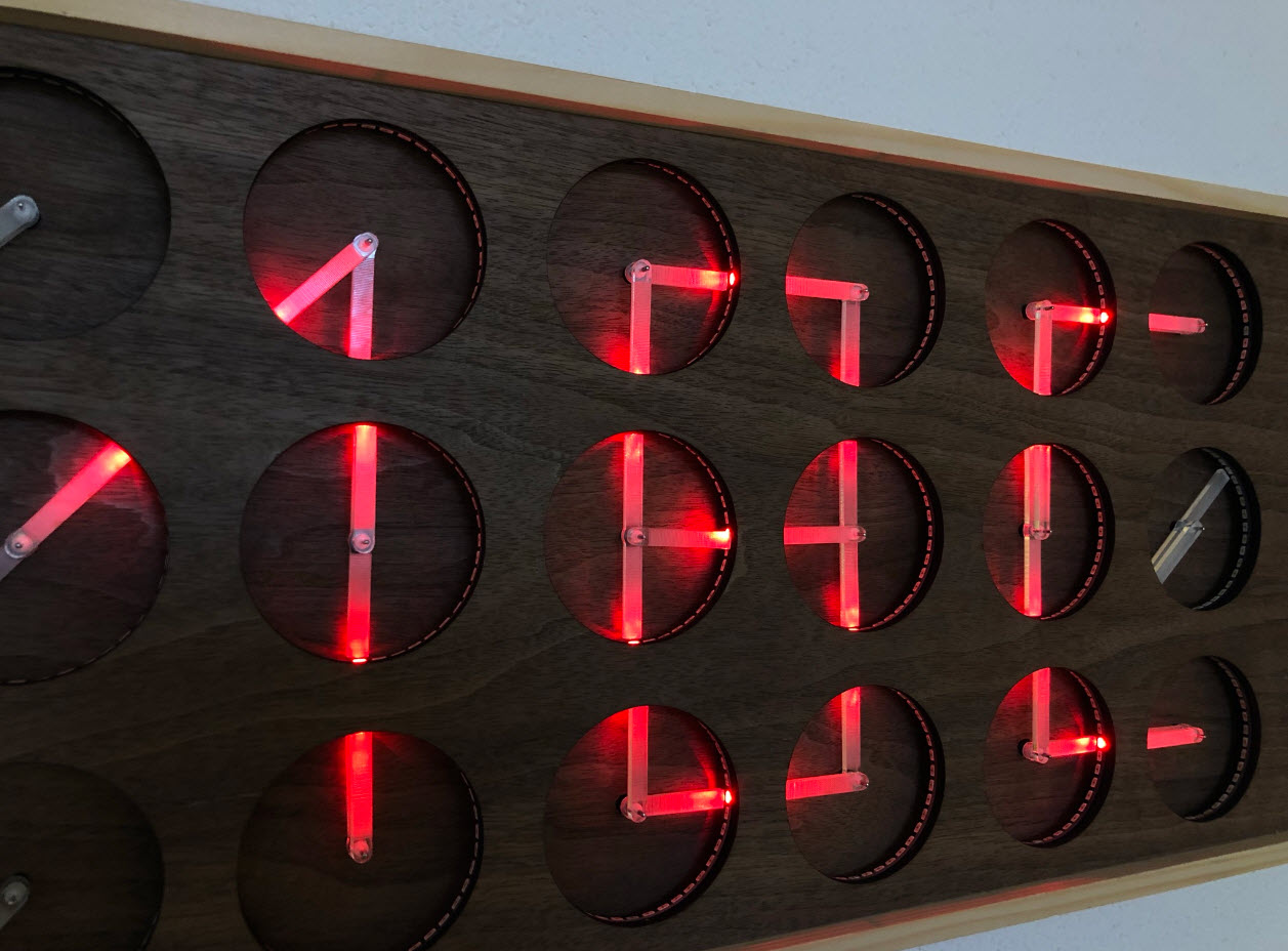
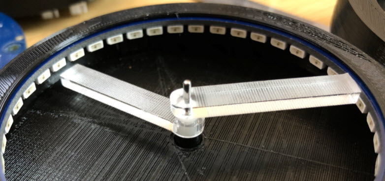
With magnets and hall sensors on the PCBs it is possible to have a zero position for the motors. Optionally each board can have an individually addressable WS2812B-SIDE RGB LED ring. My version with the acrylic (PMMA) hands currently does not have a magnet attached.
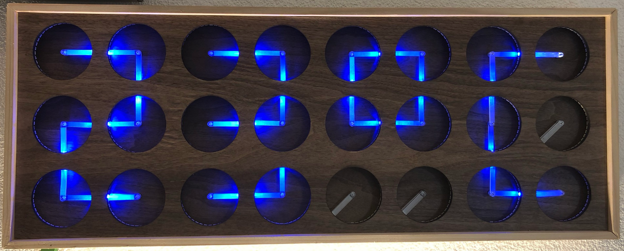
The LED’s can ‘follow’ acrylic clock hands to illuminate them or create different effects: the firmware supports up to three ‘hands’ for each clock unit:
This article does not cover building the electronics: you find the information for it on the GitHub listed as well at the end of this article. The 3D printer models and the laser cut files can be found on that GitHub too.
Material
Below is the list of the main material and tools needed. Of course you can vary things depending on your needs.
- Plywood 4 mm for the distance holder and mounting the enclosure
- 60 2×10 mm wood screws
- Wood veneer

- 24 LED Rings
- 12 MCU Boards
- 12 Motor Boards
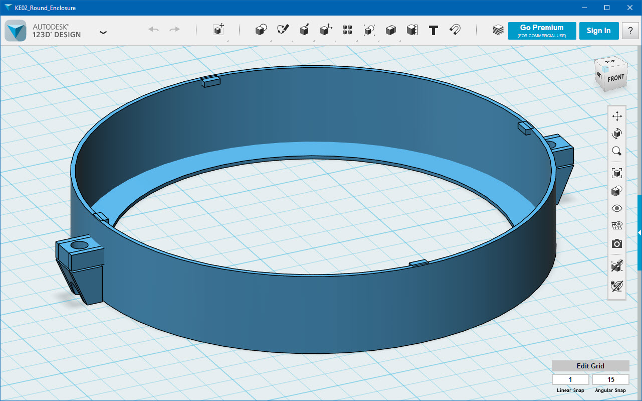
Enclosure
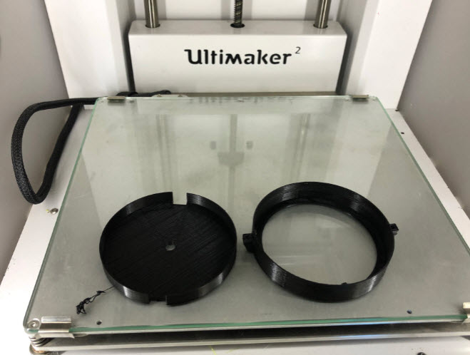
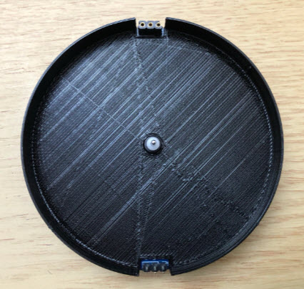
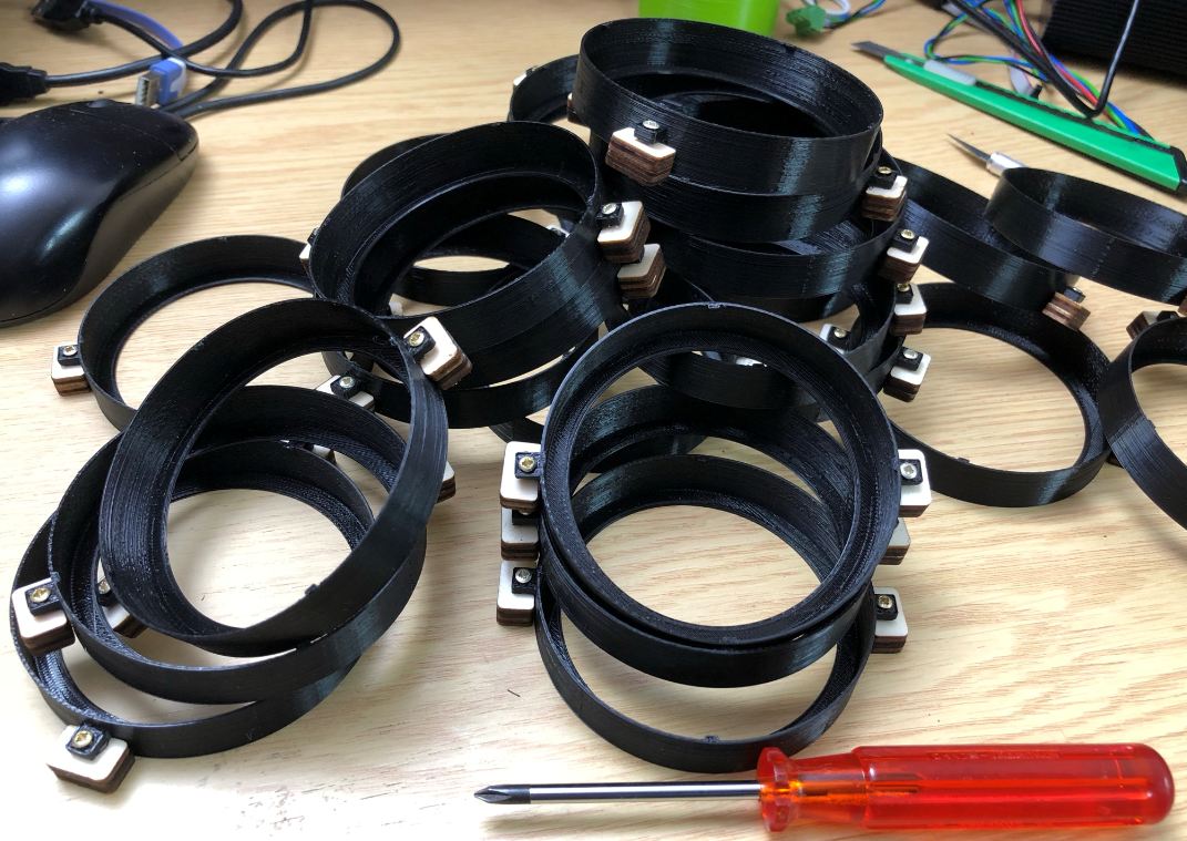
For an easy mounting the clocks get a 3D printed enclosure.
I used black PLA on my Ultimaker 2. It takes around 1 hour to print the two pieces for each clock.
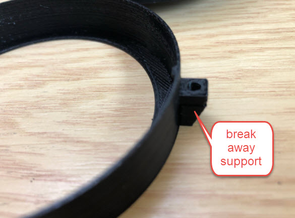
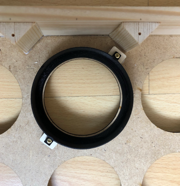
The parts are printed without support: two small support pieces are included in the design for the two mounting points: carefully break them off the outer ring:

The inlay is used to cover the PCB and protect the electronics. The inlay can get painted or covered with any other material you like. The following pictures show the assembly of the inlay and outer enclosure ring.

The inlay gets placed over the PCB:
Then mount the LED ring on top of the inlay:

Then place the outer enclosure part over it:

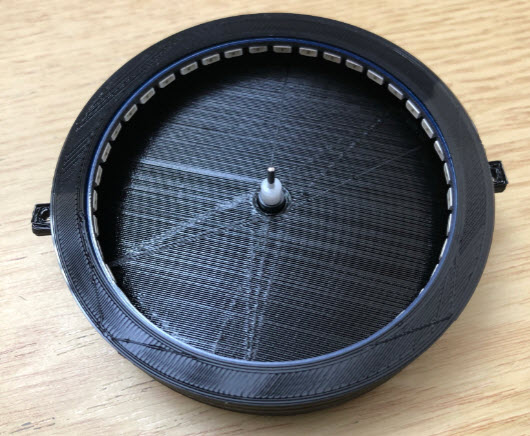
Small notches keep the PCB in place:
Repeat this for all clocks.
Inlay
The inlay can be painted or ‘filled’ with any material you like, as long is about less than 1 mm thick. I used the walnut veneer in this build.
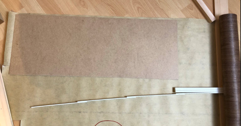
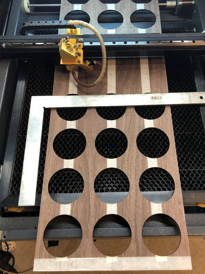
I used template (laser cut plywood) to to mark the inlays on the back of the veneer:
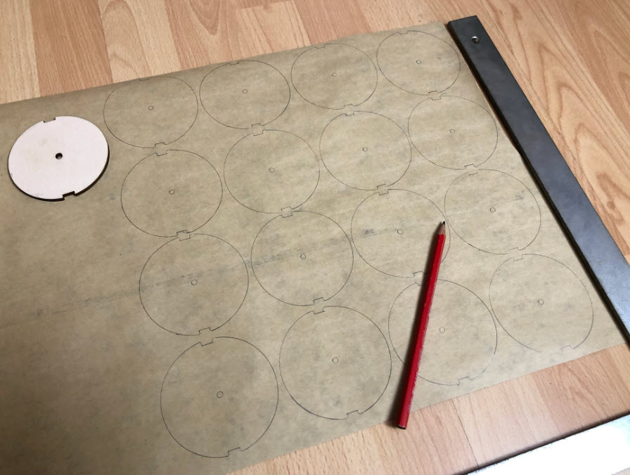
I did consider to laser-cut them, but it was easier to cut them by hand. I used a scissor and razor blade:
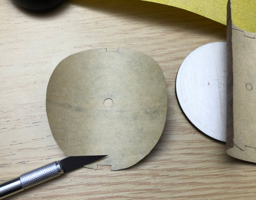
💡 to flatten curled veneer, start applying a light spray of water on both sides and press it between Kraft paper or similar, with some weight on it to keep it flat while drying.
Then glue it into the inlay:
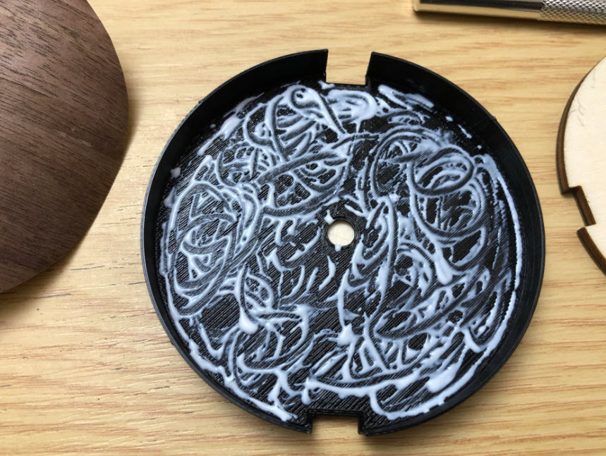
Place the veneer inside it and keep it in place for several hours with the template:
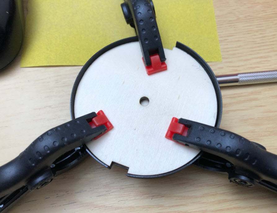
Repeat this for all inlays. To speed up things, use multiple templates and glue multiple inlays

Hands
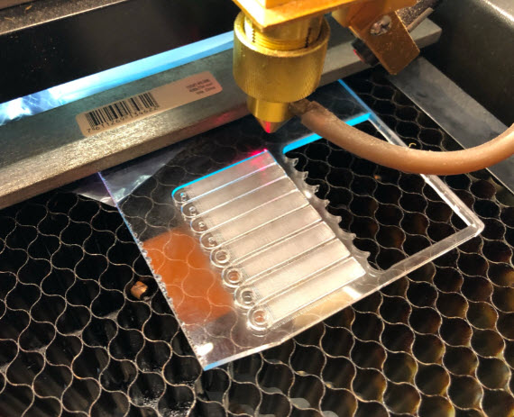
The hands get laser-cut from PMMA/Acrylic. They have been designed with Inkscape (.svg file):

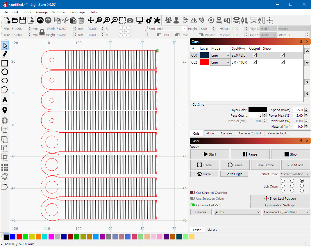
I used 3 mm PMMA (Acrylic) for the hands with my 50W laser cutter, using Cohesion 3D and LightBurn.
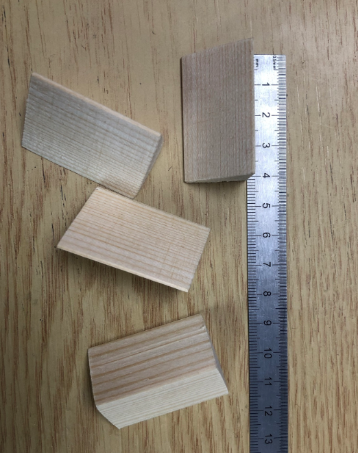
The build includes uses ‘extended hands’: you can configure for each motor if it uses a normal one or an extended one, and they can be combined.
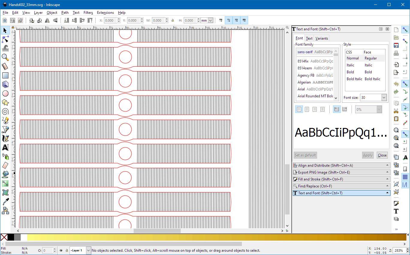
The PMMA gets engraved on both sides to create a good effect. Remove the protecting foil (if any) from the material.

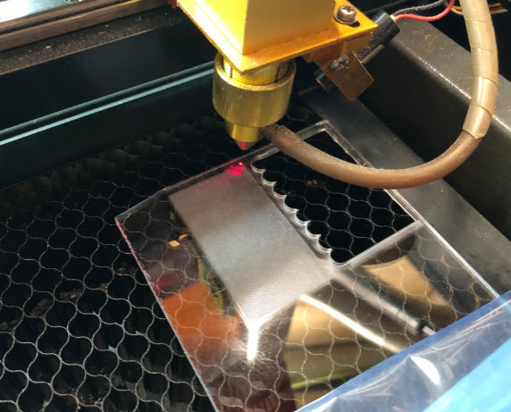
First engrave the bottom side pattern (I used 2% laser power with a speed of 25 mm/sec):
Then turn around the PMMA sheet and position the laser to the corner of the engraved bottom side:
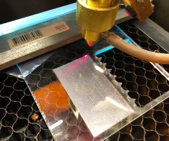
Then engrave and cut the clock hands. I used 100% laser power with a speed of 8 mm/sec:
Wash the hands with water to remove any remaining dust:
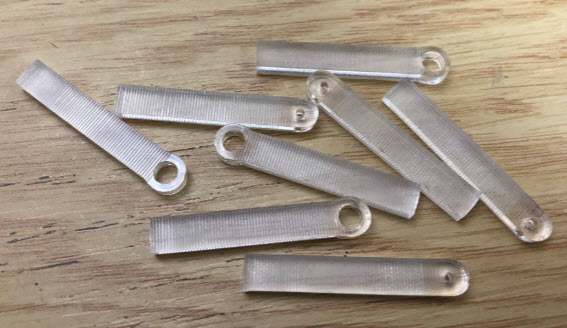
Use a screw driver or drill to carefully remove any sharp edges (if any) from the center holes.
The hands shall fit on the motor shafts tightly, but without too much force applied.
Frame
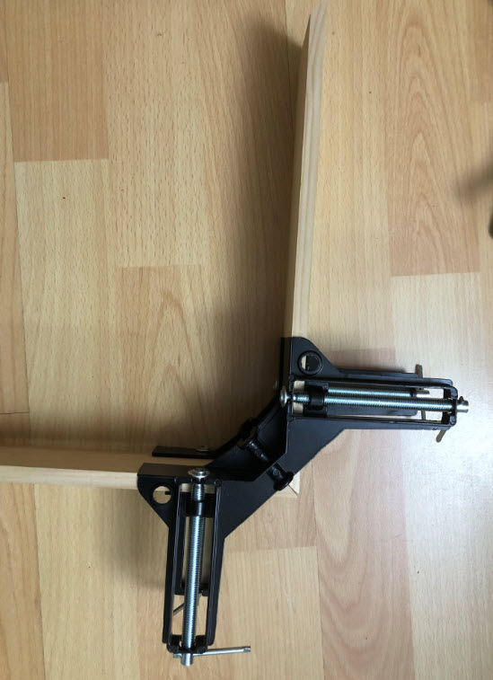
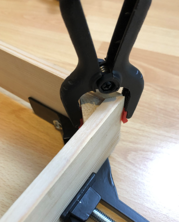
Cut the wood for the frame with a 45° degree angle and glue them together:
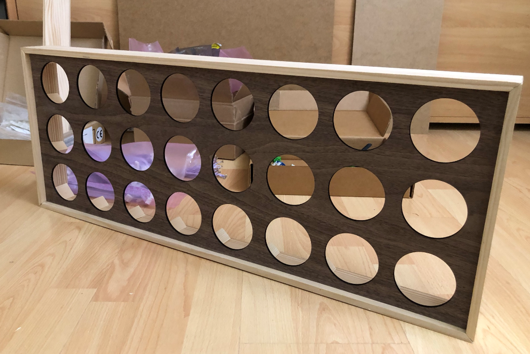
Front
The veneer gets glued on the font MDF. Use veneer glue (I used normal wood glue).
Dry it overnight with some weight on it to press the veneer and MDF together.
Use a cover tape and put markings for the center of the rings to be cut out:
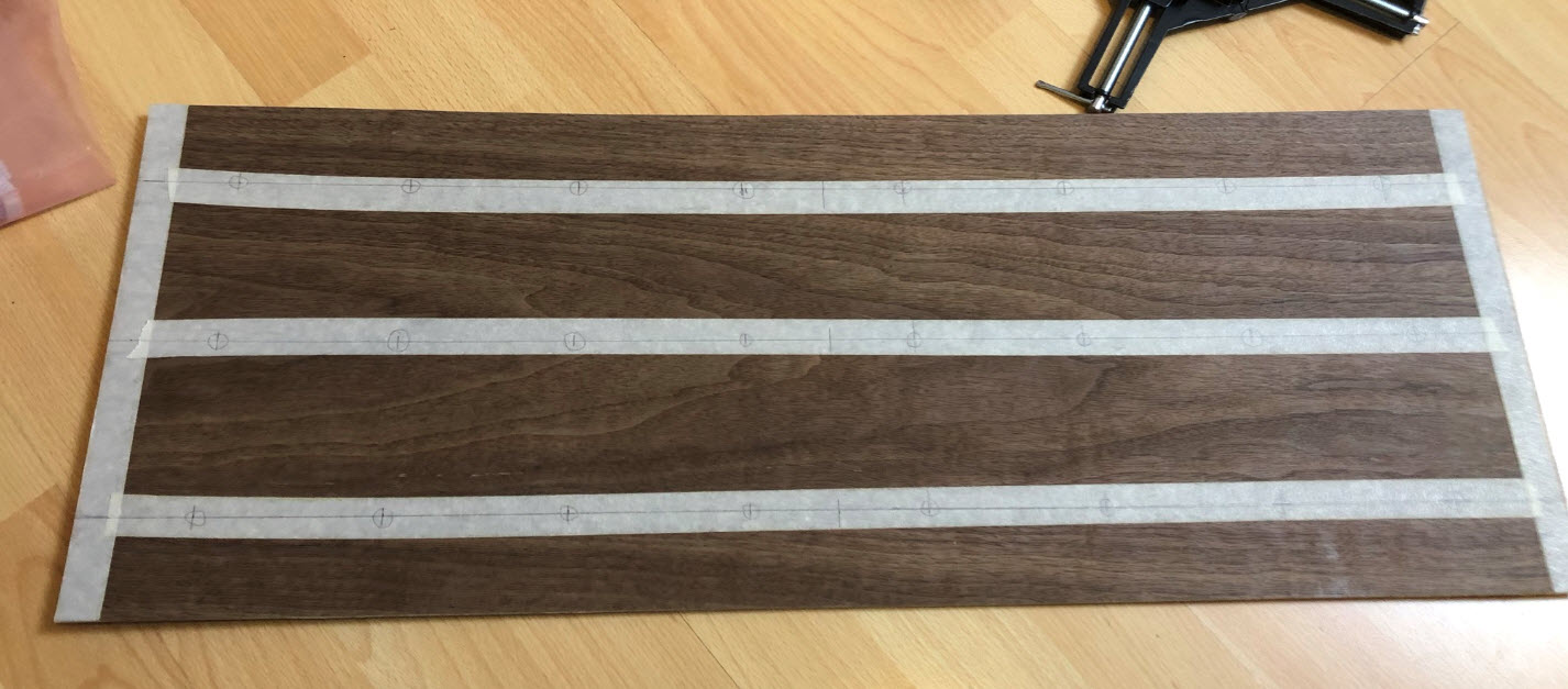
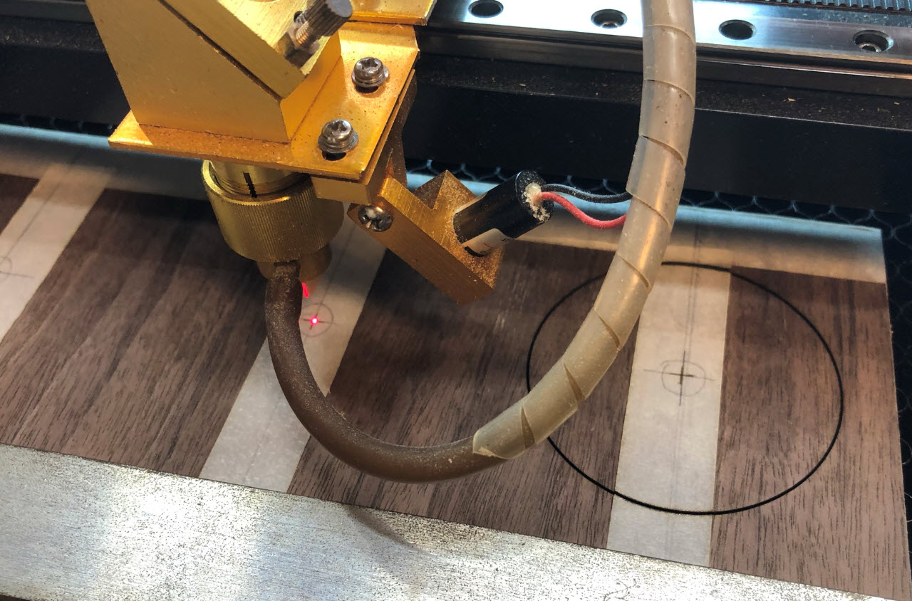
User the markings to center each hole and cut them out:
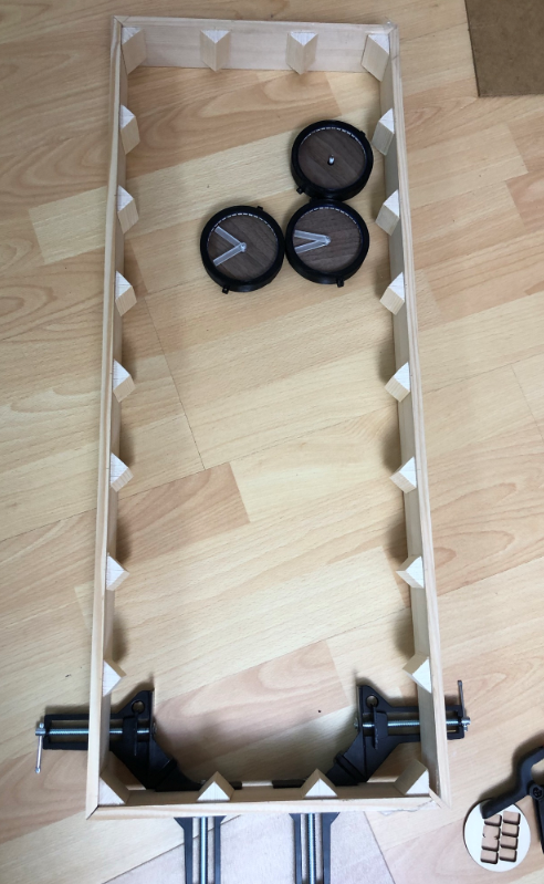
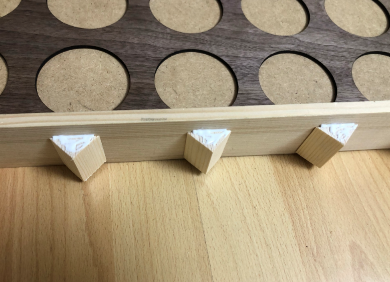
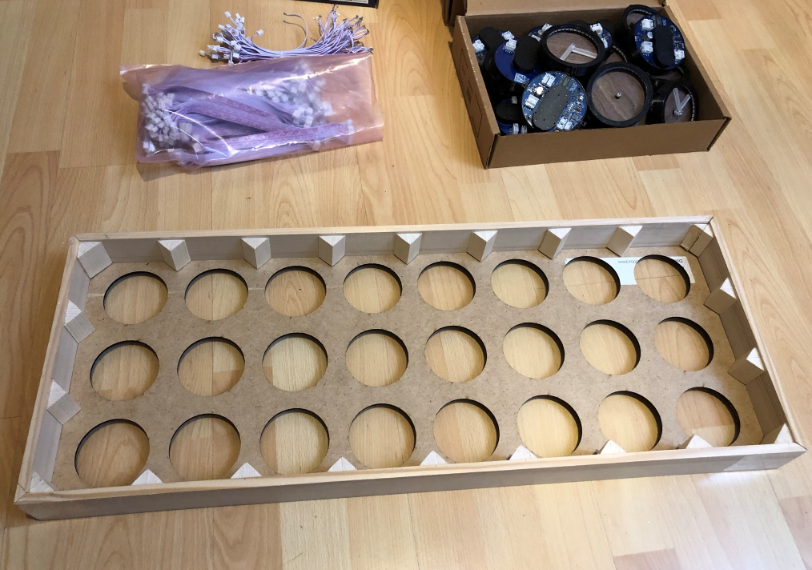
For the inside: prepare 40 mm long pieces of the triangles:
Glue them into the corners and on the side, with 5mm from the back side of the frame:
The laser cut front plate gets placed inside:

The front gets glued onto the triangles:
Mounting Clocks
Stack/glue two of the distance holders (4 mm plywood) and attach it with with screws to the clock holders:
Glue them onto the cutouts: make sure the rings are well aligned:
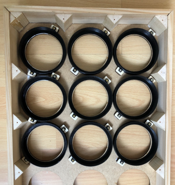
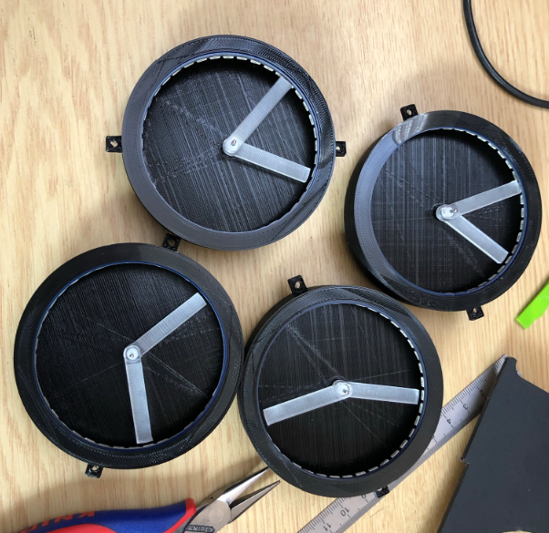
Have the clocks assembled with the rings and the veneer inlay:
Insert the clock pairs (master + remote) into the front frames:
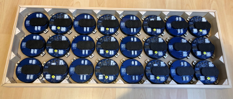

With the clocks securely snapped in, mount the hands on the front:

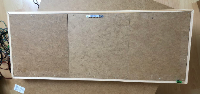
I recommend to cover the back side with MDF sheets like this:
Master
The clocks and patterns are controlled by a ‘master’ board. The master should have a a RTC (Realtime Clock) and the RS-485 connection to the clocks.
One way is to use the LPC845-BRK with a breadboard (see https://mcuoneclipse.com/2020/06/07/behind-the-canvas-making-of-60-billion-lights/):

Another option is to build the master with a tinyK22 which adds BLE and a temperature/humidity sensor.
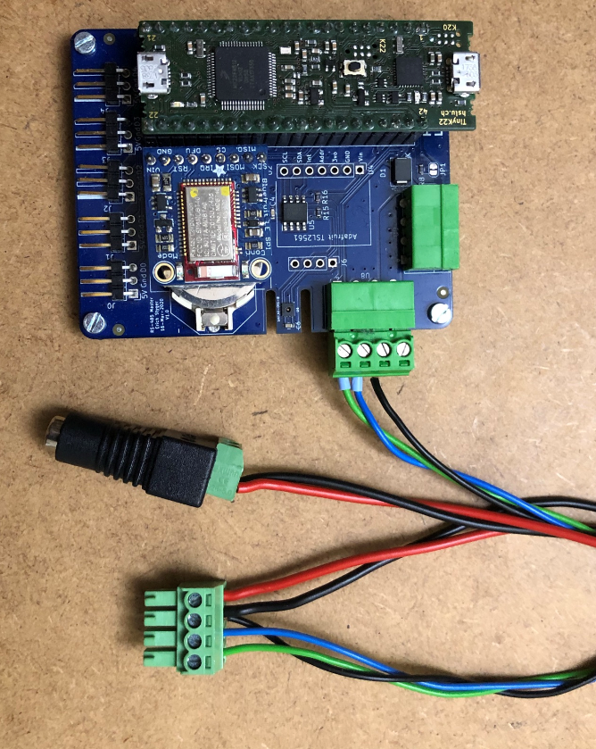
I’m using the 4pin green Phoenix Contact connectors, but you can use any other connector.
Wiring
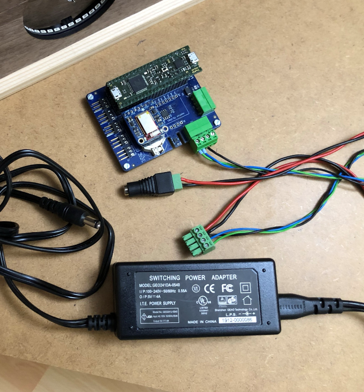
Use a good 5V Power supply. I recommend the Adafruit 10A 5V power supply or at least the 4A version.
I use a 2.1 mm Power adapter with a screw terminal block.
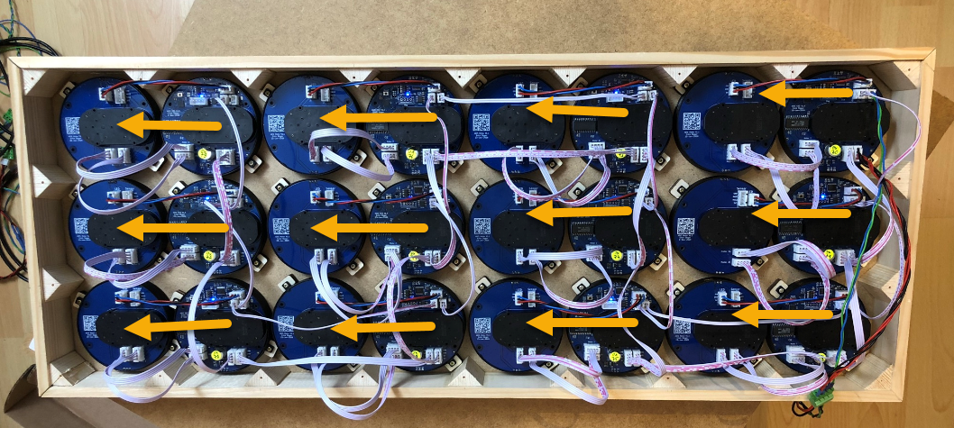
Below is a picture my wiring:
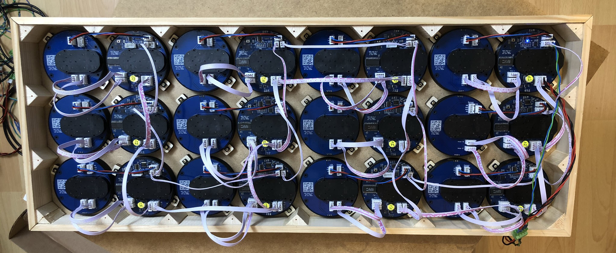
The ‘master’ board has a 5V Power In-Out, so the power is using daisy chaining. Below is how I power the boards, but you are free to use any other way. Just keep in mind that if the power line is too long there will be a voltage drop: do not chain more than 10-12 boards.
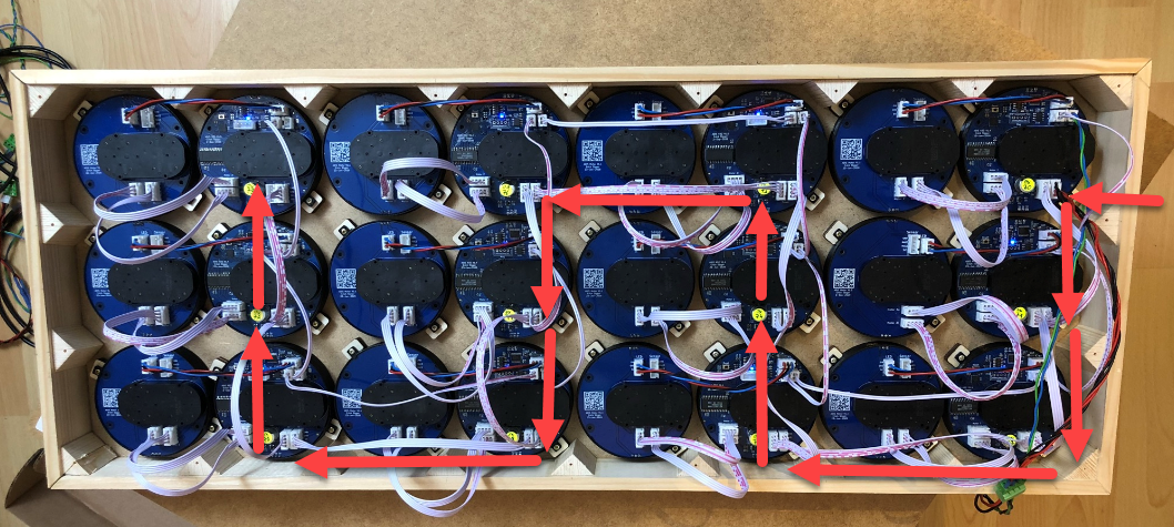
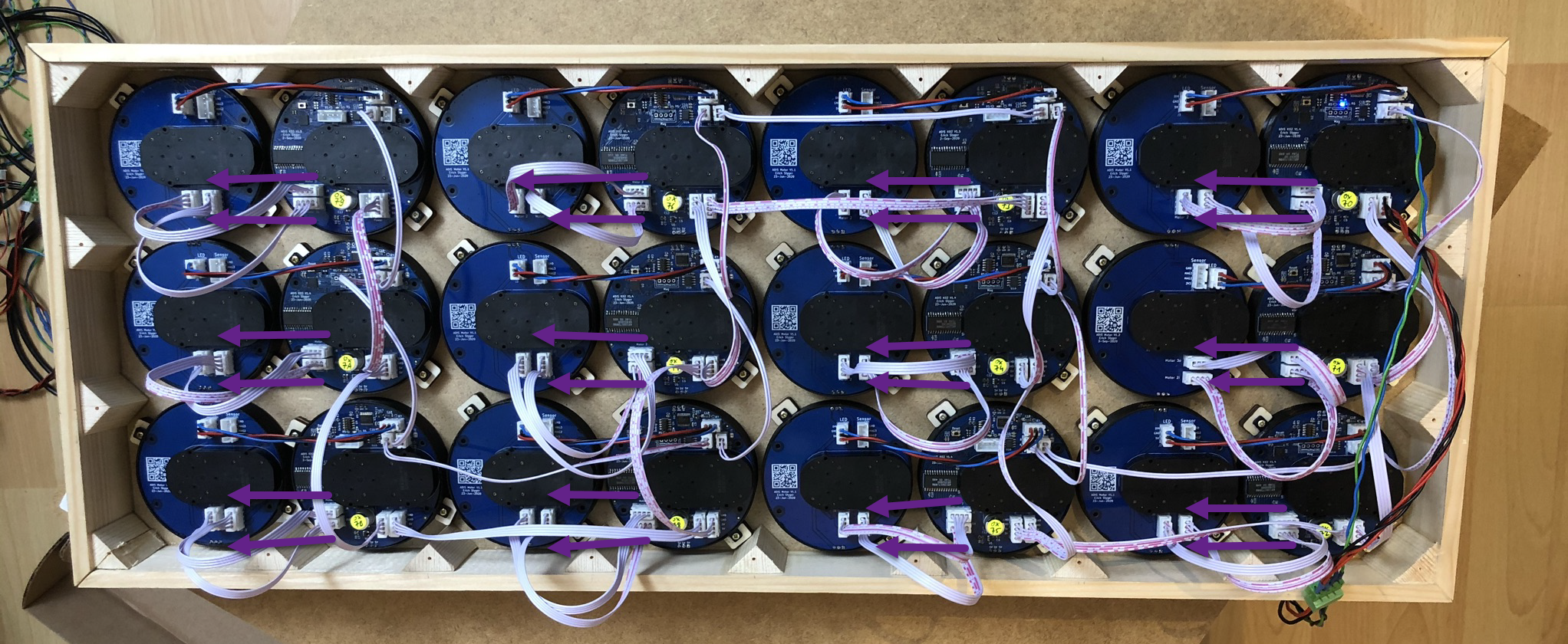
In a similar way the RS-485 is using daisy-chaining.

The wiring of the RS-485 bus does not really matter. Only make sure that the last board in the chain has the termination resistors enabled and populated to avoid reflections (see below).
What matters is the location of the board with the RS-485 address. The above image is for the PL_MATRIX_ID_CLOCK_8x3_V4 configuration. Its addresses are defined in matrixconfig.h as BOARD_ADDR_00=0x70, BOARD_ADDR_01=0x71, …, and so on. In matrixconfig.c the mapping of the boards with coordinates are defined, with x=0,y=0 as the left upper (front side) corner, and z=0 as to top-most clock handle. With the default mapping in matrixconfig.c, the location of boards with addresses (hex values!) is shown below:

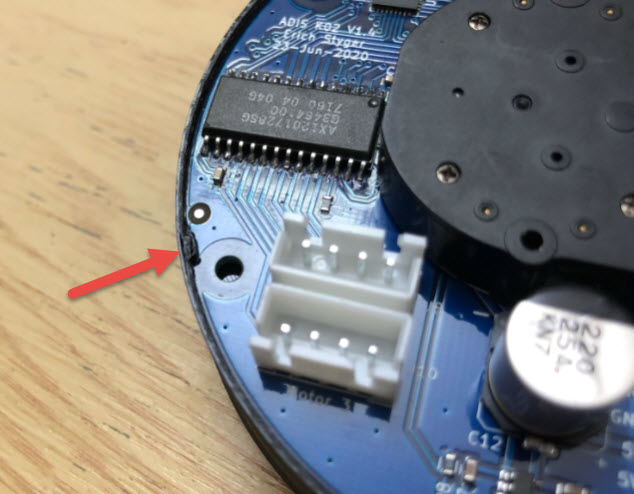
The last board in the chain shall have the J1 solder jumper closed to enable the termination resistor:

For shorter RS-485 connections it probably will work without J1 closed, but technically it should be enabled.
Below the wiring of the RGB LEDs from the MCU to the motor board:
The MCU board has two wires for the motor on the motor PCB:
Issue: Up to and including V1.5 of the MCU PCB the motor signals are swapped in the layout: the order should be 1-2-3-4 (and not 1-2-4-3):
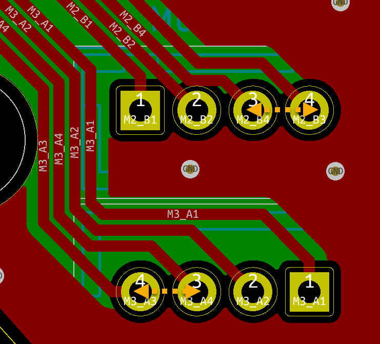
With this the remote motor is not as silent as it should be. I recommend to swap the two wires in the cable.
Software
You can use any SWD debug probe (P&E, SEGGER, NXP LPC-Link2 or MCU-Link) to program the MCU boards. As the firmware on the clocks uses SEGGER RTT as a command line shell I recommend a J-Link or J-Link EDU Mini.
The firmware uses the McuLib with the NXP MCUXpresso SDK and NXP MCUXpresso IDE. All the files are available on GitHub.
Choose your master (tinyK22 or LPC845) and the clock project (K02_128_Clock2):

Using the ‘platform.h’ in each project the firmware can be configured in many different ways (check the GitHub and Wiki).
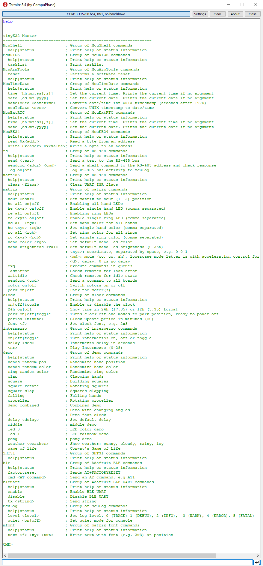
Connect with a terminal program to he master (or over BLE). Help gives a list of available commands. The ‘rs’ command group can be used to use and access the command line shell on each clock MCU board.
With this, enjoy your own MetaClockClock:
Summary
The new round clock makes it really easy to build different clock systems: the clocks can be placed in a flexible way. I hope this tutorial enables to build your own version. For all the files check out the GitHub site listed in the Links section at the end of this article.
Happy Clocking 🙂

Cancel Cable, watch clock, lot less stressful!
LikeLike
For a next iteration I’m considering to make the motor PCB connected but breakable: by default no wires to it would be needed. Otherwise the two boards could be separated, headers populated and cables used for flexible arrangement.
LikeLike
hello
See your work, it is too beautiful, look for a long time are very beautiful.To see work link, so contact you, I am in Beijing, China, I’m in advertising design, due to the outbreak of unemployment, there has been no find the right job, do you know the outbreak of the economy were hit by the economic recovery needs a process, I don’t have things to do at home. See you share is very interested in the production process, so I contacted – pcbway.com, to choose and buy the assembled PCB with electronic components make you own one, but they say BOM is not perfect, can’t order for PCB, excuse me, can you improve?I don’t know about PCB, so I want to know more about it.Looking forward to your help and reply. Thank you very much.If you have a chance to come to Beijing, I will be your guide. Nice to meet you. Have a nice day.
LikeLike
Wow this is amazing! Can you give an idea of the total cost of all materials?
LikeLike
Hi Alex,
It actually looks even better in reality as it is difficult to capture it in a video or picture. Especially at night time it feels like magic when it forms a new image.
it is roughly $13 for a single clock unit. There is a detailed BOM on the GitHub site. So if you count in wood, screws and 3D printed material and power supply you can build a 24 version for around $350, not including labor time of course.
Erich
LikeLike
Pingback: Round MetaClockClock | MCU on Eclipse
Hey Erich,
great clock! Your project helped immensely with my own clone, especially the stepper driver.
But I am having problems with the AX1201728SG on my breadboard.
My AX1201728SG runs the steppers even if I disconnect VDD and VSS. Only the motor pins, STEP, DIR and the reset pins are connected and power flows regardless. Did you come across that issue?
I noticed you used a DIO7003 power distribution switch to cut power to the stepper driver. Is there a particular reason why you used this IC and not a mosfet?
LikeLiked by 1 person
Hi David,
no, I did not come across such an issue. And I used the DIO7003 because of several factors: I have used it successfully in other designs, it is a high-side switch, it is small, it is inexpensive plus it has a built-in current limitation/protection. You won’t be able to have the same with just a MOSFET.
LikeLike
Hi Erich,
Could you be so kind to enlighten a calibration process? I didn’t see any magnets in assembling. How do you achieve zeros?
LikeLiked by 1 person
there are two ways to use the magnets: glue them to the underside of the clock hands, or engrave pockets into the hands and place the magnets there. You can see the position of the magnets here: https://mcuoneclipse.com/2019/08/25/diy-stepper-motor-clock-with-nxp-lpc845-brk/ where it uses 3D printed hands).
LikeLike
Thanks for your answer. I think for acrylic hands it would not be nice if we glue magnets. Maybe magnetic type or magnetic powder on the underside of hands? I’m not sure that it create enough magnetic fields for sensor.
Am I right that you calibrate acrylic hands manually (without any magnets)?
LikeLiked by 1 person
You can order really small super-magnets, so they are barely visible. I do have clocks without magnets (the smaller ones) which I can calibrate by hand one time, and I do have clocks with magnets which can automatically recalibrate if needed. I have one 24-clock version without magnets which now is running for more than 6 months without loosing any steps and no need for re-calibration, same for another 60-clock version which does have magnets, but I used them only at the beginning.
LikeLike