In Getting Started: Raspberry Pi Pico RP2040 with Eclipse and J-Link I used a SEGGER J-Link EDU for debugging: unfortunately, probably because of silicon shortage, these EDU probes are out of stock everywhere. Luckily, there is a solution: just use another Raspberry Pi Pico!

This turns a $5 Raspberry Pi Pico board in to a very usable and versatile debug probe.
With the ‘Picoprobe‘ firmware, you can turn the Raspberry Pi Pico board into a SWD debug probe. I’m showing this here using OpenOCD and Eclipse on Windows.
Picoprobe: build and load firmware
The Picoprobe documentation can be found in the Pico Getting Started Guide. See “Appendix A: Using Picoprobe”.
a) build it on Windows:
Download the zip from https://github.com/raspberrypi/picoprobe and extract it to a folder. Or clone it from GitHub:
git clone https://github.com/raspberrypi/picoprobe.git
Run a console in that folder:
mkdir build
cd build
cmake -G"Eclipse CDT4 - Unix Makefiles" -DCMAKE_BUILD_TYPE=Debug -DCMAKE_ECLIPSE_VERSION="4.22" ..
make
This has the benefit to create Eclipse projects as well, and I can debug it, see Getting Started: Raspberry Pi Pico RP2040 with Eclipse and J-Link.
Then program the Pico with the build output (build/picoprobe.uf2): Press the BOOTSEL button and copy the picoprobe.uf2 file to the device.
or b) download the binary UF2 file from https://www.raspberrypi.com/documentation/microcontrollers/raspberry-pi-pico.html#debugging-using-another-raspberry-pi-pico
Picoprobe Wiring
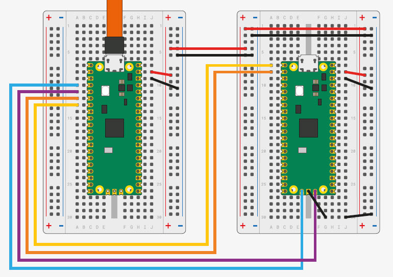
The Picoprobe offers SWD Debug with an optional UART connection to the target. The following shows the connection between the probe (left) and the target (right):

- Red: Pico VSYS -> Target 5V (optional to power the target with 5V)
- Black: Pico GND -> Target GND
- Blue: Pico GP2 -> Target SWCLK
- Purple: Pico GP3 -> Target SWDIO
- Orange: Pico GP4/UART1 Tx -> Target Rx (optional for UART connection)
- Yellow: Pico GP5/UART1 Rx -> Target Tx (optional for UART connection)
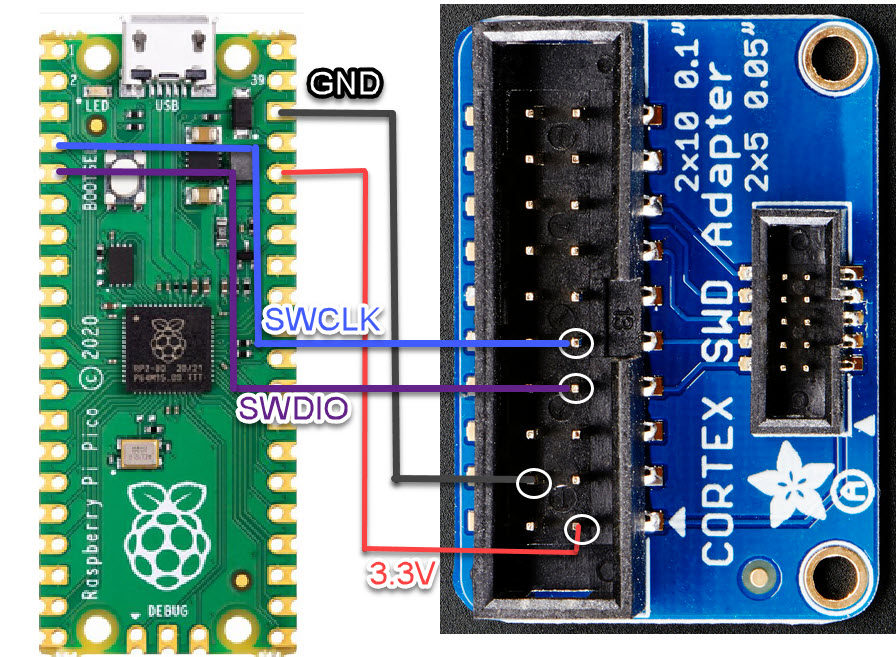
I prefer the following to have a standard SWD Debug connection, e.g. using the SWD/JTAG adapter from Adafruit:

- Black: Pico GND -> Pin 4 (GND)
- Red: Pico 3.3V Out -> Pin 1 (VccSense): this one is optional and allows to power the target with 3.3V
- Blue: Pico GP2 -> Pin 9 (TCK, SWCLK, Clock)
- Purple: Pico GP3 -> Pin 7 (TMS, SWDIO, Data)
That way I do have a ‘generic’ SWD Debug connection and connector. This is what I use below, because the target PCB has added a standard 10pin SWD header:

Windows Drivers with Zadig
The Picoprobe exposes two USB interfaces: one for the the USB CDC (Virtual COM port) which is supported out of the box on Windows. For the Debug probe with OpenOCD we need to install and assign the WinUSB driver to it. For this I need the Zadic (https://zadig.akeo.ie/) tool. Run it to install the libusb driver for the attached Picoprobe (Interface 2):

With this, the driver should be correctly installed:

OpenOCD
The current version V0.11.0 of OpenOCD does not include support for the Picoprobe. As building OpenOCD on Windows is painful, there is a built version of available on https://gnutoolchains.com/arm-eabi/openocd/. I’m using here 20211118. Download the archive and extract it. Later in Eclipse we need to point to that OpenOCD.

Eclipse Embedded C/C++ OpenOCD Debugging
To use OpenOCD with Eclipse, I have to install the Eclipse CDT OpenOCD plugin:

The update site depends on the Eclipse version used, and I’m using this:
https://download.eclipse.org/embed-cdt/updates/v6/
Eclipse OpenOCD Launch Configuration
With the plugin, I can create a new debug configuration with OpenOCD for the Picoprobe:

I’m using in the Debugger settings the following config options which includes OpenOCD support for FreeRTOS:
-f interface/picoprobe.cfg -f target/rp2040.cfg -c "$_TARGETNAME_0 configure -rtos FreeRTOS"
💡 It is important to point to the special openocd_rp2040 executable, and it has to point to the gdb of the same toolchain which has been used to build the binary.

With this, I can debug with Eclipse and the Picoprobe:

Summary
Using OpenOCD with the Raspberry Pi as debug probe is a good and inexpensive alternative, especially if other debug probes are not at hand. OpenOCD works well with Eclipse for the RP2040, so this is a good alternative if you do not have a SEGGER J-Link at hand. As an extra benefit I get a UART-2-USB virtual COM connection to the target which the J-Link EDU does not offer.
To make the wiring simpler: I plan to create a simple adapter board for the Raspberry Pi Pico, similar to the one from Fabien Chouteau. So stay tuned …
Happy debugging 🙂
Links
- Picoprobe firmware: https://github.com/raspberrypi/picoprobe
- Raspberry Pi Pico getting started guide: https://datasheets.raspberrypi.com/pico/getting-started-with-pico.pdf
- Adafruit SWD/JTAG Adapter: https://www.adafruit.com/product/2094
- Pico Debug Header Specification: https://datasheets.raspberrypi.com/debug/debug-connector-specification.pdf
- Zadig: https://zadig.akeo.ie/
- Pre-Built OpenOCD for Picoprobe: https://gnutoolchains.com/arm-eabi/openocd/

Well done. And I’ve also noticed that most of Segger’s debug tools out OOS, as well. Fortunately, I have few of the EDU models, so I should be ok, personally, but there’s always the possibility of accidentally releasing the magic smoke. It happens. This would be a useful alternative. Especially since I have a few Picos handy.
LikeLike
Thanks! I’m using the EDU for most of my classroom labs, and from time to time one gets damaged, probably because of ESD. So my stock is running out, and I’m happy to know that I have an alternative too.
LikeLike
Have you tried using rpi pico as swd debugger on other microcontroller for example nxp or stm32?
LikeLiked by 1 person
Yes.
LikeLike