“A picture says more than 1000 words.”
I don’t know the source of that quote, but for sure it is true for every developer and engineer too. Engineers need to work a lot with numbers. But numbers can be transformed into pictures and graphs which can make complex things and relationships easier to understand. Verifying proper functionality of a PID closed loop controller or watching sensor values with a nice plot is definitely something very useful. Would it not be great to watch sensor data changing over time in a chart like the one below?
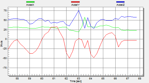
Accelerometer Graph
One way is to export data and then show it e.g. in Excel (which has been great chart functions). But even better, if this could be done directly with data provided from the target board? If you think this is hard to do, then I can show you how this can be done in a few steps with the help of a very nice tool: FreeMASTER 🙂
FreeMASTER
FreeMASTER is a graphical tool to read or write memory on the target, either using a COM (serial) port on the host PC or using a dedicated communication protocol (BDM, JTAG, or CAN). FreeMASTER is provided for free-of-charge on the Freescale web site (requires registration). There seems no uniform spelling of FreeMASTER. Even Freescale uses different spelling (FreeMaster, FreeMASTER, PCMaster, so do I in this post too 😉
FreeMASTER is using the application binary file and debug information for the location of the global variables in the target memory, and is able to display them in ‘real time’ on the host. ‘Real time’ means that it does not impact the target code execution ‘much’. This makes it a great tool to visualize or change variables ‘on the fly’. Additionally it allows to send ‘callbacks’ to the target for advanced control. More about this at the end of this article.
The downside is: it is not very easy to use. Jim Trudeau wrote a great article about the capabilities of FreeMASTER which is a starting point. Similar to the comments on his blog, I have not found I have not found good documentation or tutorials how to use it. This is very I hope I can close a gap.
I want to pass a big ‘Thank you!” to Yayra Kwaku for reminding me that I had the ‘FreeMASTER’ topic in my bucket list for a long time. As a reader of my blog and as intern at Freescale, he explored FreeMASTER and he provided me important tips and ways how to use FreeMASTER. Without this, I would not have been able to use FreeMASTER or to explore the features easily. THANK YOU!
So with this, I hope you find this tutorial helpful and that it gives an easier way to learn this tool. I promise: it is indeed a great tool, it just needs some learning. And a tutorial 🙂
❗ FreeMASTER is only available for Windows. So if you are using Linux, you are (yet again) not covered 😦
Tutorial Outline
In this tutorial I’ll show how to use FreeMASTER to visualize the accelerometer values on the FRDM-KL25Z board and to change the LEDs on the board.

MMA8451Q Accelerometer on the FRDM-KL25Z Board
I’m using Processor Expert with CodeWarrior for MCU10.4. The steps are very generic so it can be used for any other board or toolchain configuration, e.g. IAR, Keil or standard Eclipse. To communicate between the microprocessor and FreeMASTER, I’m using the OpenSDA USB CDC (serial over USB) connection. As starting point, I’m using the project I had created in a tutorial about how to use the accelerometer.
Installation
FreeMASTER comes in two parts:
- FreeMASTER Application: this is the visualization tool itself, running on the host. It comes with built-in drivers to communicate with the target through debugging/JTAG/BDM devices like P&E Multilink.
- FreeMASTER Communication Drivers: this includes serial communication software drivers to communicate with the target, and source code for other connections like BDM (Background Debug Mode) or CAN and USB. So if you are not going to use the Processor Expert component (I’m going to use below), then you can use the files in this package to be incorporated into your application.
Instructions to download and install are very simple:
- Go to NXP.com and download FreeMASTER from the ‘Downloads’ tab. You need both the ‘FreeMASTER Application Installation’ and ‘FreeMASTER Communication Driver’.
- Run both setups (order does not matter) to install the application and the communication drivers.
Project Setup
In the next steps I will add a FreeMaster Processor Expert component to my project which will communicate with the FreeMaster application on the host machine.
💡 I’m using Processor Expert as it comes with a FreeMaster component, and only requires to add two function calls. The limitation is that the Processor Expert component only works with RS-232/SCI, and not with other communication ways like CAN or USB CDC.
I need to insert two calls to FreeMaster library functions in my code. In order to view my variables, they need to be global variables.
💡 Global variables can be ‘static global’ or ‘external global’. They just need to be present in the Dwarf (Debug Information) of the application binary file.
The next steps outline what needs to be done to transform a Processor Expert project into a ‘FreeMASTER ready’ one.
Adding FreeMaster Processor Expert Component
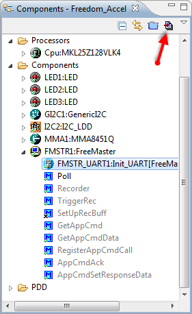
From the Components view, add the FreeMaster component to the project. It can be found in the Components Library view in Processor Expert:
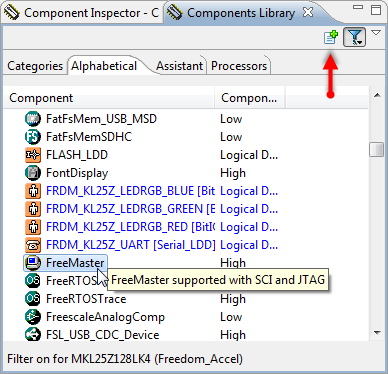
FreeMaster in Components Library View
To add it to the project, either double-click on it, use the ‘+’ icon or drag&drop the component to the project.
In the Component Inspector, enable Oscilloscope, Recorder and Application command:

Configuring FreeMaster Component
💡 ‘Recorder’ is a feature I’m now not covering in this tutorial, but I’ll have it enabled.
UART Configuration
Next step is to configure the UART: I select the device (e.g. UART0) and enable the Clock gate in the Init_UART sub-component. Then I configure a suitable baud (9600 baud in this example) with divisor and oversampling ratio values as below:
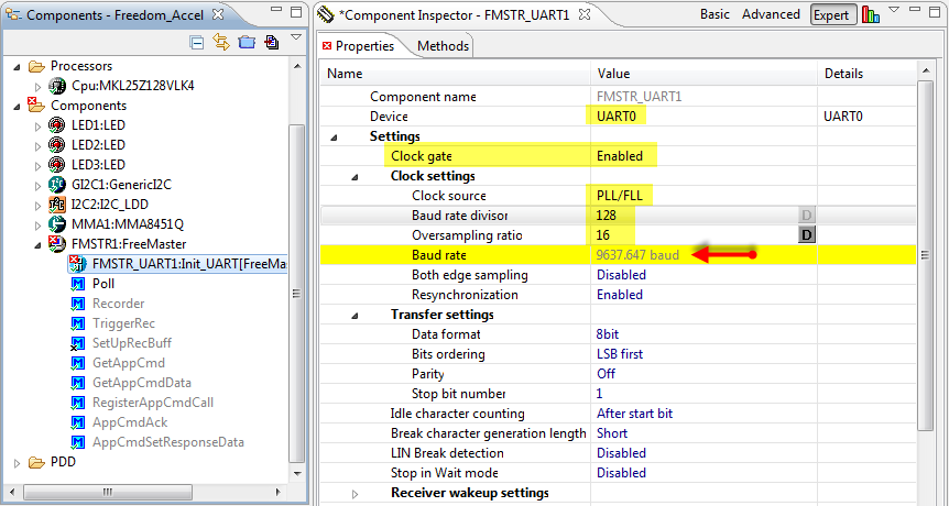
Init_UART Configuration for 9600 baud
❓ It is too bad that the FreeMaster component is using the Init_UART component (why?). It is very complicated in and not intuitive to set up the Baud rate with Init_UART. Why is it not possible to set up the desired baud as in the AsynchroSerial component? And with this way of component, it is not possible to say use USB or CAN?
Next to configure the UART RX and TX pins:

UART Pin Settings
Finally, I enable the error interrupts (so the Init_UART component is happy about the settings):

Error Interrupt Enabled
Generating Code
With this, there should be no errors, so time to generate code, either with the context menu on the ProcessorExpert.pe file or with the button below:
Generate Code
There are the following three warnings in the Problems view:

FreeMaster Warnings
They remind me that I need to call the FMSTR1_Poll() function to keep the communication alive with FreeMaster, and that I need to use the FMSTR1_Recorder() function to sample variables in the recorder.
❓ I have the requirement to have my projects error and warning free. Unfortunately I have not found a way to get rid of these warnings? Even if I’m using the functions, the warnings do not go away?
The FMSTR1_RegisterAppCmdCall() function can register added callbacks and is not used in this tutorial (I will use a direct way. More about this later).
Poll() and Recorder()
I add both FMSTR1_Poll() and FMSTR1_Recorder() calls to my application main loop. For this I can use drag&drop to place the function calls into my source file:
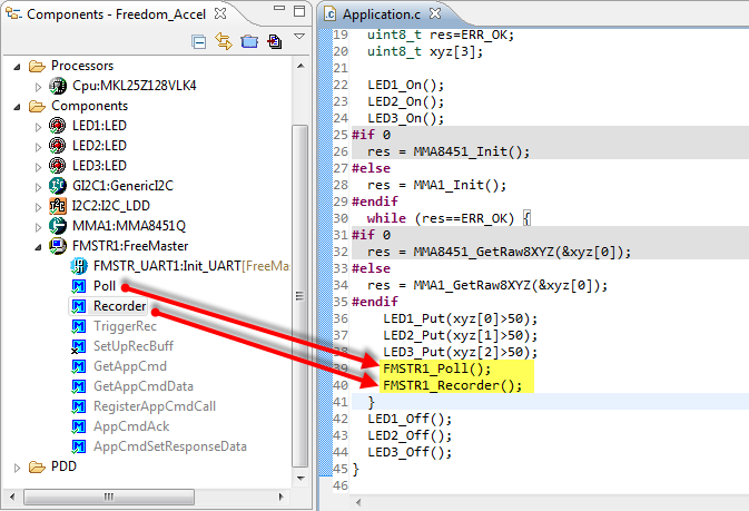
Added Poll and Recorder Calls
If needed, add the proper include to my source file:
#include "FMSTR1.h"Global Variables
FreeMASTER is accessing the target memory. For this, a variable needs to be at a fixed address. Accessing local variables on the stack does not make sense, as the memory address will change all the time. Therefore, any variable I want to watch, needs to be a global one.
💡 FreeMASTER can use as well directly the address of a memory location. But it is more user friendly to find the address of the memory location, based on the variable name.
So if I want to see my x, y and z accelerometer values (which are local variables in my example), I need to copy them into global variables. For this I add extra code to make accelerometer values global:
Global Variables for FreeMaster Access
❗ Of course if the variables to watch are already global, no copy is needed. But if you want to monitor local ones, then you need to make them global. Please refer to the project sources on GitHub.
With this, my application is complete, and I can build and download it to the board as usually.
FreeMASTER Application
Run FreeMASTER from the shortcut installed:
Running FreeMASTER from Shortcut
The application probably will complain about a communication port error:
FreeMaster Error (Could not open the communication port)
Click OK to get rid of it.
💡 Consider changing the FreeMASTER shortcut to add the project *.pmp file (more about this later), so it loads automatically your project at startup.
Select the menu Project > Options:
Project Options
Here we need to setup the communication and which binary file (map file) to use.
COM Port
Select the COM port where you connect to the board and the Baud (see above) you have configured on your board:
COM Port and Baud Settings
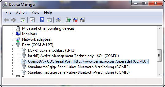
💡 If you are unsure which COM port is used, check the communication ports in the Windows Device Manager:
COM Ports Used in Windows Device Manager
Map (or ELF) File
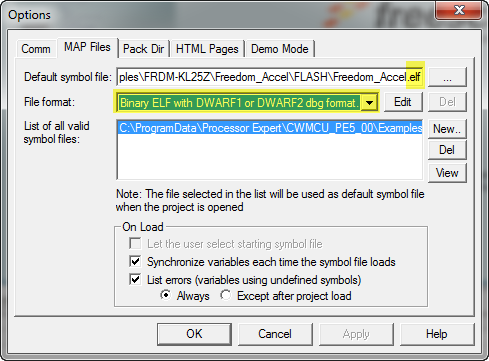
FreeMASTER is using the information inside the debug information of the ELF/Dwarf file. Under the ‘MAP Files’ tab, browse to the .elf application file and specify the File format:
Selected ELF File
❗ FreeMASTER is using old/outdated Windows libraries for the browse dialogs. As a result browsing Libraries in Windows 7 or 8 will not work, so you need browse to the absolute drive path.
This completes the communication setup. Press OK.
Creating Variables
With the .elf file specified, we can add variables to watch in FreeMASTER. Use the menu Project > Variables:
Project Variables
Initially, the list of variables is empty, so we are going to create new ones with ‘Generate’:
Generating Variable List
💡 I could use ‘New’ as well, and then setup things from scratch. Generate is a better way in my view as it automatically populates the settings with the settings from the debug information.
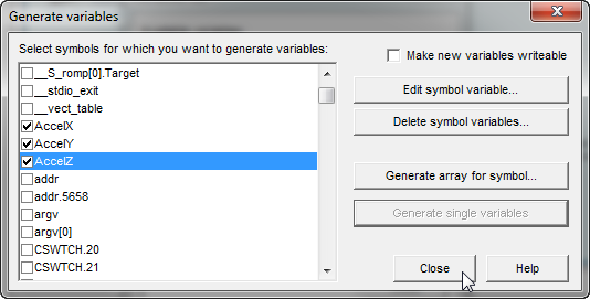
Then I select the variable and use ‘Generate single variables‘:
Generate Variable
I do this for all my variables:
Variables created
Then use ‘Close’ button. And I have my variables listed in the variables list:
Accelerometer Variables Created
Using the ‘Edit…’ button on a variable shows the details about it. For example the sampling period can be changed:
Changed Sampling Period
💡 FreeMASTER is using the data types for the variables as defined in the .elf file. In the above case, AccelX is defined as uint8_t in the sources. It can be changed in this dialog to a signed fixed point type (or any other type) as needed.
Then close the dialogs with OK.
Saving Project Settings
Now it would be a good time to save the project settings so it can be loaded later again:
Saving Project Settings
Otherwise if you close FreeMASTER, you will lose all your settings. So do not forget to save your settings on a regular base.
💡 I recommend to save the project file inside the CodeWarrior project folder. That way the path to the .elf file will be relative to the project root, and allows easier sharing of the file e.g. in a version control system. Additionally if you specify that project file as argument to the PCMaster.exe (that’s the name for FreeMASTER executable), then it will load that project file at startup.
Creating Subblock
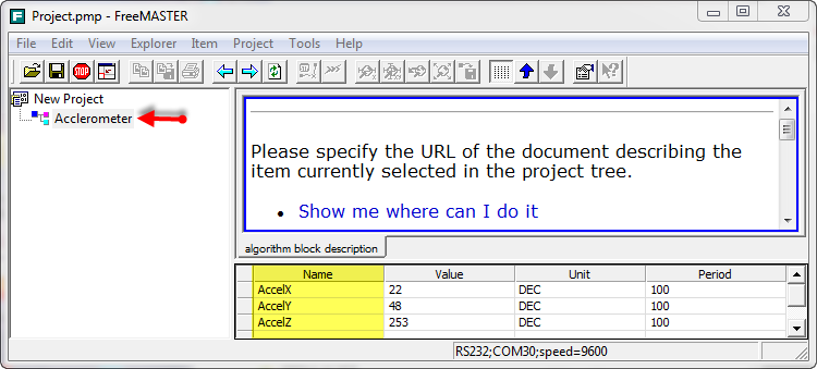
To show the variables, we need to create a ‘Subblock’. To do this, right-click on the project icon and use ‘Create Subblock…’:
Creating Subblock
Provide a (hopefully 🙂 ) meaningful name:
Naming Subblock
In the ‘Watch’ tab move the variables you want to watch to the right side using the ‘Add ->’ button:
Watch Tab with Watched Variables
Then close the dialog with OK.
Watching Variables Values
How to see the variable value? Select the subblock and I can watch the variable in the lower part of the window:
Showing Accelerometer Values
💡 To watch variables changing over time like in above view, I can use the ‘live view’ of the CodeWarrior debugger too.
Watching Variables in Graphical View
Having the variable value updated periodically is one thing. But I want to see the values plotted over time. To view the variables in graphical mode, right-click on the subblock and then create a scope:
💡 ‘Scope’ is meant here like a oszillo’scope’, and not in the sense of ‘scope’ in the sense of programming languages. So not like the ‘scope’ of a variable 😉
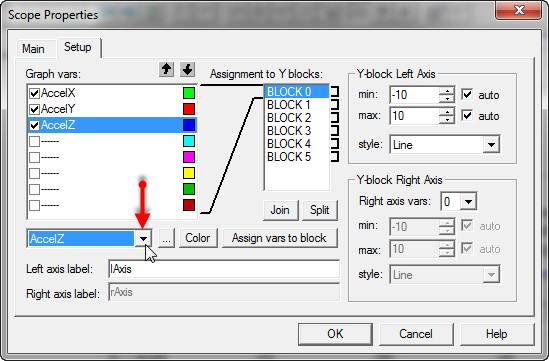
Creating Scope for Graphical View
Then use the Setup tab to assign variables to colors, using the drop down to select variables:
Assigning variables to colors
Close the dialog and we are ready to show the graph.
Showing the Variable Plot
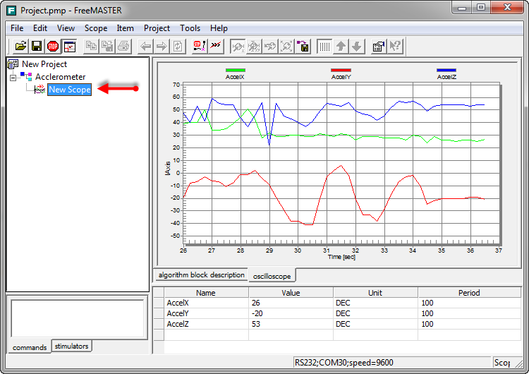
To show the plotted graph, select the scope created and enjoy the graph in the ‘oscilloscope’ tab:
💡 There is a ‘algorithm block description’ tab which I do not cover here. See the documentation about how to use it. You can hide this tab too if needed.
Showing the plotted graph
💡 I’m using the TWR-LCD module as display to a similar graphical view of data at runtime. Data is sent to the TWR-LCD with I2C. It is fast and does not require a dedicated PC like with FreeMASTER. But it requires a hardware LCD.
If data transfer is paused, I can zoom in/out the graph to inspect details:
Pause Scope Data Transfer
Changing Variables through FreeMASTER
It is not only possible to read and monitor variables: I can write them too. For example I want to control if the LED’s are used or not. So I use a variable ‘enableLED’ for this:
static bool enableLED = TRUE; /* if LED's are used or not */ void APP_Run(void) { ... if (enableLED) { LED1_Put(xyz[0]>50); LED2_Put(xyz[1]>50); LED3_Put(xyz[2]>50); } ... }As before, I add that variable:
enableLED Variable
And this time I mark it as writable in the ‘Modifying’ tab:
Modifyable variable
That way I can now control and change my application from FreeMASTER by changing this application variable:
Changing Variable
App Commands: Passing Information to the Application
With FreeMASTER it is possible to send commands to the application. That way commands with parameters can be passed to the application without using additional global variables. It is like if I would call the application on the board from the PC host. I can have multiple of such commands (each with a unique ID) on the host to control my embedded application. This can be used for testing purposes or for demonstrating functionality or to stimulate the system.
To show this, I’m going to send a custom command to the application to toggle the RGB LED on the board. I want to implement the following interface:
/*! * \brief Toggles a LED on the board. * \param[in] ledNO Which LED to toggle, 0 for red, 1 for green and 2 for blue LED. * \return Error code, 0 for OK and 1 for failure. */ uint8_t toggleLED_cmd(uint8_t ledNo);FreeMASTER Application Command Definition
First, I define the command in FreeMASTER. Right click on the subblock and select Properties:
Subblock Properties
Then create a new Application command with ‘New..’:
New Application Command
In the ‘Definition’ tab I give the command a name and a code number:
Application Command Definition
💡 The ‘Code’ is a numerical value I can use later in my application to differentiate between commands. It is more like a ‘command ID’.
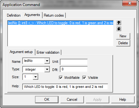
In the ‘Arguments’ tab I specify the argument(s) to be used:
Application Command Argument
I can have multiple arguments. In this example I just need one: the ledNo as a one byte of integral type.
Similar to this, I define the return codes:
Application Command Return Codes
With specifying a message icon, I the given return code text will be shown in a dialog box (more about this later).
Handling FreeMASTER Application Commands in Application
I define three variables in my application (they can be local variables too):
static FMSTR_APPCMD_CODE cmd; /* application command */ static FMSTR_APPCMD_PDATA cmdDataP; /* pointer to application command data */ static FMSTR_SIZE cmdSize; /* size of application command arguments */With the following call
/* check application commands */ cmd = FMSTR1_GetAppCmd();I check if an application command has been received.
💡 It is possible to register callbacks for application commands using RegisterAppCmdCall(). That way the FreeMASTER library will directly call the callback. In my example I’m using the polling method.
FMSTR1_GetAppCmd()returns the command ID (‘code’) I have defined earlier in FreeMASTER. If no command is present, it returnsFMSTR_APPCMDRESULT_NOCMD.If there is a valid command, I query for the size of arguments and the arguments itself:
/* check application commands */ cmdDataP = FMSTR1_GetAppCmdData(&cmdSize);This returns in
cmdSizethe number of bytes of the arguments, and a pointer to the arguments as return value.Then I need to acknowledge the reception of the command and return the return value. Otherwise FreeMASTER on the host will show a timeout. Acknowledgement is performed with
/* check application commands */ FMSTR1_AppCmdAck(0); /* acknowledge the command */Here I return the return codes I have defined before in FreeMASTER (e.g. 0 for OK, 1 for failure, etc).
In summary, my application command handling source then looks like this to toggle the LEDs:
cmd = FMSTR1_GetAppCmd(); if (cmd!=FMSTR_APPCMDRESULT_NOCMD) { /* received command */ cmdDataP = FMSTR1_GetAppCmdData(&cmdSize); if (cmd==0 && cmdSize==1) { /* ToggleLED_cmd (id: 0) has just one byte argument */ switch(*cmdDataP) { case 0: LED1_Neg(); FMSTR1_AppCmdAck(0); /* acknowledge the command */ break; case 1: LED2_Neg(); FMSTR1_AppCmdAck(0); /* acknowledge the command */ break; case 2: LED3_Neg(); FMSTR1_AppCmdAck(0); /* acknowledge the command */ break; default: FMSTR1_AppCmdAck(1); /* failed */ break; } } else { FMSTR1_AppCmdAck(1); /* acknowledge the command with failure code */ } }Sending Application Commands
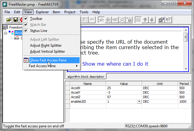
To send the application commands, make sure that the ‘Fast Access Pane’ is enabled:
Show Fast Access Pane
With ‘Send’ a command is sent:
Sending Application Command
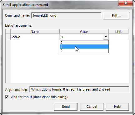
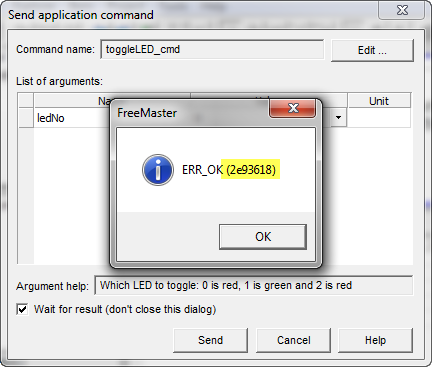
Double clicking in the command or using the ‘Send Dialog…’ opens a dialog:
Send Command Dialog
Make sure to check the ‘Wait for result’ box if you are interested in the return value. The argument values can be changed too:
Selecting different parameter value
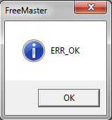
With ‘Send’ the command gets sent to the application. Based on the return value and the return value settings, a dialog box is shown (only if ‘wait for result’ is checked):
FreeMASTER return value box
Stimulating Variables
Similar to changing variables, it is possible to stimulate variables. Stimulation means that FreeMASTER will change the variable over time. For this I have added a variable ‘stimulatedVar’ to my application.
To create a stimulator, I use ‘New…’ in the ‘stimulators’ tab:
new stimulator
Then I select the variable to stimulate, plus the time-table with the values:
Stimulation Time Table
There are a few important details which might not be clear from this dialog (and I might be wrong as I have found no documentation about this feature in the delivered documentation, but I will prove my points below 🙂 ):
- The Time in the table are absolute time points, relative from the start of the stimulation.
- Between two time points the value between it gets *interpolated*, with the frequency given the ‘approximate time step‘ setting. So if this is 100 ms, then a new value will be written every 100 ms. So every 100 ms a new value gets written.
- The stimulation either runs once, or in a loop if the ‘Run in the loop‘ is enabled.
As visible with the graph, the stimulation is ‘approximate’. It seems not be at the very millisecond. Still, this is a very useful feature for changing variables on the target over time.
To run the stimulation, either double-click on it or use the context menu:
Running Stimulation
The running script is showing with a ‘green walking person’ 😉 :
Stimulation Running
To show what happens with the time-table I have set up, I show the plot of the changing value:
Stimulated Variable Graph
In summary, I can now watch variables, change them, display them in graphs, send my custom commands to the application, and I can send stimulation values :-).
Creation of Advanced Control Pages
There is more in FreeMASTER, and one big thing I have not touched is using advanced visualization pages in FreeMASTER. I have not found much information about this, except an application note AN2263 from 2004. It explains how FreeMASTER can be extended with HTML pages and to use ActiveX.
❓ The dependency on ActiveX might be the reason FreeMASTER is not available on Linux?
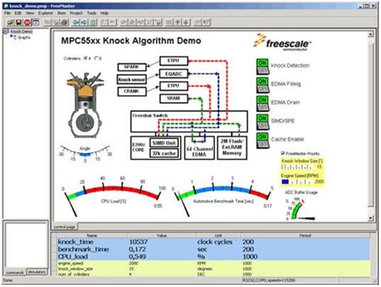
How this could look like is shown in the article by Jim Trudeau on FreeMASTER:
Visualization Example (Source: Freescale, Jim Trudeau)
Using Debug Connection
Another part which I have not touched yet is using a Debug Connection to the target, instead of using the serial communication protocol. This requires a JTAG/BDM run control unit like a P&E Multilink. The advantage is that this does not need changes in the application running on the target and does not need a serial port. The downside is that at least with the P&E Multilink debugging while running FreeMASTER is not possible, at least not for ARM/Kinetis.
Troubleshooting Tips
As with any software and tools, FreeMASTER is not perfect. Below are some tips & tricks in case of problems. Be free to post a comment if you have more hints and tips!
No Updates
One problem is that the variables in FreeMASTER do not get updated any more: they are frozen. I saw the application on the board running properly, and the serial connection was transmitting data. But FreeMASTER somehow was stuck. Closing FreeMASTER did not help. Logging out the user was not enough, it required a full machine reboot :-(. I had that case several times, and it seems to be related to the fact if switching back and forward between FreeMASTER and normal serial connection (having a terminal program open and connected to the board if not using FreeMASTER ). It seems that FreeMASTER then blocks the serial port, and only a reboot of the machine helps. So be careful with using terminal programs (especially on the same COM port) in parallel with FreeMASTER.
Host Suspend/Resume
The other thing I noticed: Suspend/resume on a notebook while FreeMASTER is running can be problematic. I need to exit FreeMASTER first, then suspend the notebook, and start FreeMASTER again after resume. Otherwise a ‘Can not detect board information’ error can show up:
Can not detect the board information
Sometimes it helps to unplug/re-plug the USB cable of the connected board (using USB CDC). In some cases I had to reboot the machine.
💡 The above issues might not be directly related to FreeMASTER itself, but to the USB CDC drivers (I used the FRDM boards with OpenSDA USB CDC drivers). It could be that using a ‘real’ COM port would work fine, but I have not tried this yet. But avoiding the notebook to enter suspend definitely helped in combination with FreeMASTER. Suspending the notebook with other application (terminal programs) seems not to be a problem.
Return Code Number in Message
A ‘#’ in the return code dialog box is supposed th show the return code number in the message:
Return Code Symbol
However, this did not work for me:
Wrong Return Code Value
I do not have a workaround for this (yet).
Return Code Dialog Box
The return code dialog box did not work initially (not really sure why?), as it should (it did not show up at all).
return code dialog box
Sending commands worked, but not the dialog box. It worked after closing FreeMASTER and loading the project again.
The other catch is: the dialog box shows up if the command is executed only if you do it with the ‘Send’ context menu. But it does *not* show up if using the ‘Send dialog’ way with the ‘wait for result’ unchecked. To show the return dialog box using the ‘Send dialog’ way, the ‘Wait for result’ needs to be checked.
💡 It would be more intuitive if each command would have a check box ‘show return code dialog box’.
Debugging
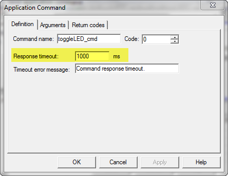
Debugging the application while connected to FreeMASTER is possible. But it is not possible to debug the board if FreeMASTER is using the debug port (instead of serial port). I was able to use FreeMASTER on the same USB connection to the FRDM-KL25Z board, both having the debugger and FreeMASTER running the same time. The CodeWarrior debugger is using the USB cable to debug, while the same the USB cable is used with USB CDC. But the target should not be halted during FreeMASTER application command processing, otherwise a timeout will occur:
Timeout Error
If that error happens otherwise, try extending the command response timeout:
Application command timeout settings
Summary
FreeMASTER is a free-of-charge tool to monitor, visualize and change variables or memory on my embedded system. It is suitable for a ‘few’ variables, as ultimately it will not allow to transfer a lot of data in a very fast way. But it works very well for a few bytes every few 100 ms. An ideal tool to inspect a system to see what is going on, either with a serial connectivity or using a debug port. Although FreeMASTER is intrusive to some extend, it adds a lot of value during the development of a system, as it allows to monitor and change the system in nearly real time.
For using serial connectivity, It requires that the target system adds a FreeMASTER library/source support. It offers using a debug port too, but then you cannot debug and visualize the same time (at least with ARM targets). It is using a viewer on the host PC (Windows only) which communicates to the target. Altough the FreeMASTER user interface and runtine library is not very easy to use, it is very easy to use with the help of Processor Expert. But it would be great if Processor Expert could support other protocols beyond Serial. For example the FreeMASTER communication drivers have the FSL USB Stack CDC sources added, but there is no way use it with Processor Expert. Unless Freescale would release a better component which would allow more flexible connections, I probaly need to implement my version if it to use something like my USB CDC component.
Unfortunately FreeMASTER is only available for Windows and no other host operating system. It seems that the FreeMASTER architecture and libraries used (e.g. ActiveX) does not make it easily portable to other systems. It is understood that such a tool is useful as a standalone version, but I wish it would exist as plugin in Eclipse. That would make it even more useful, and would certainly solve the cross-platform issue.
Neverless, FreeMASTER is a very useful tool. And I hope that tutorial is useful if you were searching for a tutorial about FreeMASTER as I did ;-).
Happy FreeMASTERing 🙂
PS: The accelerometer project used in this post is published on GitHub.


Erich as always you did an excellent job. If memory servers me PCmaster was the original name and when Freescale came about form Motorola it was changed to FreeMaster. None of that really matters.
The early usage was for motor control visual feedback, so the few App Notes and documentation make the package seem to be for DSCs only. We beat our way through usage for motor tuning and drive information in our robots with not enough time to write an App Note. Besides our company is to small by Freescale standards to publish our App Notes.
You are correct in there is no Note out there on how to use and/or configure FreeMaster which in itself is a shame.
Keep up the great work.
LikeLike
Hi Bill,
thanks for feedback and reading :-). Yes, most of the things I have found is DSC oriented, at it looks like only for DSCs (with USBTap/EtherTap) it is possible to use FreeMaster while debugging (if using the debug connection). But I think the value of that tool is well beyond motor control, but unfortunately it got labeled as such.
LikeLike
Erich, I think the original intent was for motor control readback but you have shown what we have not had time to do. I am looking at using it as the data source for joint motion on a screen (robotic arm). We have some other ideas but are not ready to release the thought just yet.
LikeLike
My old friend 🙂 FreeMASTER is perhaps the single most useful and valuable unsung tool in the FSL tool chest.
LikeLike
Glad to hear you met an old friend :-). It is like you wrote in your blog a gem, but an unpolished one. And if it would have at least some of the capabilites of National Instrument LabView, that would make that tool really outstanding.
LikeLike
Hi Erich, great job!!
Use Freemaster a while ago and today I learned many new things 🙂
When you made the post on USBDM and Freedom board I use it with Freemaster and I did not use the Freemaster component in my code, and is much faster than for UART. Would be interesting to see you try 🙂
LikeLike
Hi Carlos,
which target/board did you use with USBDM and FreeMaster?
LikeLike
KL25Z128
LikeLike
Hi Carlos,
how have you selected USBDM? I don’t see OpenSDA or USBDM in the FreeMaster connection settings?
LikeLike
Hi Erich,
There is the FreeMASTER communication plug-in that allows to access the target hardware over an alternative communication interface. This plug-in supports several BDM interfaces based on open source firmware including USBDM.
To select the USBDM, in the menu Project > Options click on the Plug-in Module and select the “FreeMASTER BDM Communication Plugin” in the drop-down list. Then press the Configure button and select USBDM.
The FreeMASTER communication driver is available at the bottom of this website:
http://www.freescale.com/webapp/sps/site/prod_summary.jsp?code=FREEMASTER&fpsp=1&tab=Design_Tools_Tab
LikeLike
Hi Tomas,
thanks, I need to try this out!
LikeLike
Hi all,
Being an old and very attached user of FreeMaster ( or PcMaster at the beginning of its story ), i’ve just to add a small note to the Erich’s article : FreeMaster view all the global or STATIC variables . In other words , you can view a variable internal to a function like this :
void func( void )
{
int a;
…..
}
simply by adding the static qualifier : static int a;
The static qualifier, infacts, says to he compiler to allocate space in RAM for that var and to not use the stack.
LikeLike
Hi Luca,
thanks for that additional point: yes, indeed, ‘static locals’ can be used too. I just add the note that some compilers might use very special names in the symbol table, so it might be hard to identify them.
LikeLike
Hi Erich, great job as usual.
Despite I’m a very old Freemaster user, your tutorial taught me a lot: thank you very much.
I just would like to point out that Freemaster for KL is not able to read MCU registers (sometimes useful to check configuration on target when you can’t put breakpoints) because target side firmware reads 32 and 16 bit variables (so registers too) byte by byte.
The program jumps to hard fault handler in this case.
Anyway this is OK for S08 MCU where most of registers are 8 bits wide.
Will it be possible to make a modification in the processor expert generated code?
Of course workaround is to stop code generation and modify the generated code but it does not look so smart 😉
LikeLike
Hi Roberto,
this sounds like a bug in FreeMaster to me. Have you reported it already to Freescale? And now I need to learn something from you: how can I read the registers?
thanks,
Erich
LikeLike
Erich,
More like a limited human design, goes back to earlier comment about DSCs which are 16-bit. Now it would be great if FSL would take this wonderful tool and expand it.
Bill
LikeLike
Hi Erich, thanks for your reply.
Yes I think it’s a bug too and I have already reported it to FSL…
Anyway to read a register:
Menu Project\Variables\New. The “usual” form will appear: enter for istance register name as variable name and its address in the edit box below, specifying type and size. Then you can set sampling period…That’s it.
On KL04 to read RTC_TSR
variable name = RTC_TSR
address = 0x4003D000
type = unsigned fixed point
size = 4
Roberto
LikeLike
Hi Roberto,
ok, I see. I was thinkig that you mean the core (CPU) registers, and not the memory mapped peripheral registers.
LikeLike
Maybe my poor english vocabulary lead to this misunderstanding.
Anyway that’s OK now.
Thanks again for this tutorial and all other ones.
Roberto
LikeLike
No, no, it is not your vocabulary! ‘Register’ can mean CPU register or ‘peripheral’. Always good to clarify.
LikeLike
Hi Erich,
I am also using FreeMASTER in my ‘Programming Microcontroller’ Course at my University. The tool is perfect to teach the student in online calibration and even for a HIL enviroment by using the interface between FreeMASTER and Matlab. All this is possible with a free licence. so first of all thank you to Freescale for providing this. However it is not everything nice-and-easy. The amount, the level of details and its widespreaded distribution makes it hard to get used to the tool. Although you are doubtless one of the worldwide experts in everything around the Freescale ecosystem you discovered a lot of obstacles during your work with it and there are still some questions open. Imagine how hard, better say frustrating it could be for a 2nd year student. So what I would love to see is a central place on the Freescale Website that collect everything about FreeMASTER and also has sufficient examples how to use the tools for the different purposes. I know there is already a lot available – but it would help a lot to centralize it.
Another thing are the available communication plug-in’s. I am planning to use the TCP Interface (via Ethernet). The belonging plug-in is marked as ‘experimental’. So I balk a little bit to start the project because I know I will have to solve a lot of things on my microcontroller – but it would be hard if I always have to question the host side as well.
So my conclusion: Great tool for many important things during the developement of an embedded system. However a little bit more attention and development from Freescale side is necessary to get its whole potential.
Best Regards
Markus
LikeLike
Hi Markus,
many thanks for your write-up, and this exactly matches what I have encountered while using FreeMaster on my own. I’ll pass this to my Freescale contacts, so hopefully this will be considered.
LikeLike
Great to see the profile of FreeMaster being raised, I have used it since it was PC Master and find it very helpful.
One thing that can be done is to use the FreeMaster driver on your micro and then implement your communications from your own PC software. You can then design your own UI without limitations. I used Visual C# Express to do this, any tool that can write to a serial port can be used. The protocol is fully documented. Just watch out for endian swaps.
Note that I found an issue with the Coldfire V1 Processor Expert component for FreeMaster
LikeLike
Hi Ian,
yes, I have seen that in the forum too, thanks for posting it!
Erich
LikeLike
Hi, can you provide a link for the freemaster protocol implementation? Regards
LikeLike
You would have to check with NXP on this.
LikeLike
Freemaster can’t parse elf – “Dwarf section corrupted”…
LikeLike
Hi Max,
just to check: is it a valid ELF/Dwarf file? And the Dwarf (debug) information has not been stripped off?
I hope this helps.
LikeLike
Hi, Erich
Project created by the wizard are creating a .elf file per default. In my property window of the project (debugging page): debug level maximum(g3), debug format dwarf-2, Other debugging flags -gstrict-dwarf.
Do you have any suggestions? Thanks.
LikeLike
I would try to set the compiler to no optimization. Which compiler/toolchain are you using?
LikeLike
I get the same error “Dwarf section corrupted”. My ELF file is compiled with -g3 and -O0. I’m using GCC version 4.8.0 which outputs the Dwarf 4 superset of Dwarf 2. Is it possible Freemaster is unable to parse certain Drawf 4 sections and this results in the error “Dwarf section corrupted”.
LikeLike
I have very well possible that Freemaster is not able to read Dwarf 4, as to my knowledge FreeMaster is using its own parser. There should be a new FreeMaster version out (V1.4), although I have not tried it yet, but you might give it a try. I’m using v1.3.
LikeLike
Hi Erich,
I’m using FreeMaster V1.4 in fact.
Thanks
Stephen
LikeLike
Pingback: Sumo Robot Battle Tips | MCU on Eclipse
Hi Erich, Thanks for the post, I have learned a lot :D.(Really xD)
I have a Question:
Can I use P&E multilink USB with FreeMaster?
I want to see the behavior of some data, but I dont see the opcion, I´m using the DEMOEM.
Thanks for Advanced.
LikeLike
Hi Braulio,
yes, this should be possible. I’m away from my boards and goodies, but from what I can tell is that it should support the P&E connection.
LikeLike
Could you help me to implement this using Keil toolchain without PE?
OR even better how to get my project started in driverless mode?
Thanks!
LikeLike
Hi Andrea,
I recommend that you use the driver suite (https://mcuoneclipse.com/2013/06/28/using-keil-%C2%B5vision-arm-mdk-with-processor-expert-driver-suite/), because with this you can get this done in a very short time, and then it works. Of course you are free to do it without PE, but then it is much more complicated.
LikeLike
Hi Erich,
I am unable to see Accelx,Accely,Accelz.
on FreeMaster, Its throwing me an error saying that the AccelX,AccelY and AccelZ symbols are not found
I am having the same problem even if i try to download your project and use it.
LikeLike
It works for me (I just tried that project again).
Are you using the same FreeMaster version? I’m using V1.3.15.0 (from Jul 27 2012).
LikeLike
Hi Erich,
I am using FreeMaster 1.3.16.0(from Oct 16 2012)
I even tried for another variable declared globally but even unable to see that variable also.
LikeLike
Looks like FreeMaster does not have the debug information. Make sure that in the Options/MAP Files tab you ahve your .elf selected, with ‘Binary ELF with DWARF1 or DWARF2 dbd format”, and that it lists the .elf in the list of valid symbol file formats (see https://mcuoneclipse.files.wordpress.com/2013/08/selected-elf-file.png). Maybe browse for that file again.
LikeLike
Hi Erich,
I have done the same I have also declared a few other Variable Globally, But none of them are visible
I don’t know what i am doing wrong.
Please help!!!!!!!
LikeLike
I really don’t know what could be wrong? Maybe post your problem in the Freescale Forum?
LikeLike
Hi Erich, veryvery useful site and post! Thank you for taking the time to make such detailed Information avalable!
However, I am having a Problem with the “Cannot detect the board Information” error you mentioned above. It is appearing always and not only when I had the PC in sleep mode. I also noticed, that I need to run FreeMaster as an Administrator explicitely, else it wouldn’t even start. I tried the USBDM plugin mode, too, mentioned by a reader. Nothing helps. Any ideas on how to get this running?
Best regards, Adrian
LikeLike
Hi Adrian,
which version are you using? I’m using V 1.3.15.0 from Jul 27 2012. I have explicitly not updated to a later version (“never change a running system” ;-).
LikeLike
HI Erich, wow, fast response! 😛 I am using 1.4.2.3 (comm protocol v3+). I see there is a 1.3.16 available at freescale.com. I’ll try this right away…
LikeLike
hmm, download says 1.3.16, installed says 1.3.15… whatever… but it still doesn’t work. What role does the communication driver play? I installed just the most recent one. Your tutorial says that this is only necessary if Processor Expert Component is not used. Do I need to use it at all if I only use the USB OpenSDA Connection?
LikeLike
I had not installed these communication drivers. From the Processor Expert component and application I’m using the normal UART of the microprocessor, which then gets translated by the K20/OpenSDA chip to USB CDC. On the host PC this is a normal virtual COM port which then is used by FreeMASTER. So all what you need for this is a working USB CDC/Virtual COM with the FRDM board. You should have that by default already. Check your Windows device manager if it shows up under the COM ports.
LikeLike
Hi,
I have tried to use PE with FRDM-K64F and to use the Freemaster PE cmponent, but it doesn’t exist, in the alphabetical order I have FreeCntr8 and then FreeRTOS, but NO FreeMaster, where can I find this?
Kind regards,
Anders
LikeLike
Yes, for strange reasons Freescale did not include the FreeMaster component into the KDS and Driver Suite distributions. I guess it was an ovesight, as it is present in CodeWarrior. I have been told that it should be included in the next release.
LikeLike
Hi agian,
I forgot to tell what version I use:
Kinetis Design Studio
Version: 1.1.1
And I have also downloaded and installed your Part1_Beans_19.09.2014.PEupd + Part2_Beans_19.09.2014.PEupd
/Anders
LikeLike
Hi Anders,
yes, it is not included in KDS (or Driver Suite 10.4). It is part of CodeWarrior for MCU10.6, but I think there is not a way how to extract it from CodeWarrior and install it in KDS. I have been told that it should be included in the next version.
LikeLike
Hi Erich,
I have now been able to port the code in the Freemaster serial driver + using the PE “init_Uart” component to set correct baudrate and pins etc to work with the virtual com port on the FRDM-K64F. And when starting the C:\Freescale\FreeMASTER_Serial_Communication_Driver_V1.8.1\examples\Kxx\TWR-K60N512\demo.pmp and just changing the elf-file + setting the COM9 which is my virtuall port,and it connects!!
BUT the var16 in the control window is the only variable that is updated and NONE of the variables in the watch view in the bottom are updated not even var16 here???
When opening the oscilloscope view doesn’t work either NOT even the var16 is showing any trace at all, have you seen this strange behaviour?
/Anders
LikeLike
Hi Anders,
is your variable a global (extern) variable? FreeMaster only can show ‘true’ global variables.
I hope this helps,
Erich
LikeLike
Hi Erich,
Its a pitty I can’t upload a screendump of Freemaster, sorry for not being clear about what I was testing: it is a Demo project that comes with the Freemaster serial driver v1.81 that has global variables var16 and var32.
See C:\Freescale\FreeMASTER_Serial_Communication_Driver_V1.8.1\examples\Kxx\TWR-K60N512\demo.pmp
And the realy strange thing is that I can see var16 but just in the “control view” I think it is some html code that uses “inline” the var16 value and this value is changing OK,
BUT in the bottom “Watch view” NONE of the variables are updated, they just show a “?” also the var16 is showing a “?”
/Anders
LikeLike
Hi Anders,
really not sure what is causing this. I’ll ask around if someone knows more about this.
Erich
LikeLike
Hello Anders,
this seems as a known bug which affects the FreeMASTER 1.4.x running on 64bit Windows systems. It will be fixed in FreeMASTER version 1.4.3 which is going to be released by middle of October at http://www.freescale.com/freemaster.
A workaround is to keep the serial port closed when the FreeMASTER starts and to open the port manually (Ctrl+K) when the FreeMASTER main window opens. You can change the start-up port settings in Project/Options… dialog.
LikeLike
We have used PCMaster for a long time with the Motorolla DSP56F80x line of controllers, recently we have swapped up to Freemaster and are experiencing issues when using the scope functionality. It will work as expected for a short period of time, it will then switch to greyscale and is no longer able to be navigated using the mouse. At some point latter it sometimes the whole scope window turns black. This happens on multiple computers so I do not think it is graphics driver based. Any Ideas?
LikeLike
I think it is a bug in the newer version. I explicitly did not upgrade and I’m still using the V1.3.15.0 version.
LikeLike
Thanks, so the bug is only in 1.4.
Any idea if it is possible to convert files back without the this file was made by a newer version errors
LikeLike
I have not upgraded to the new version, as I have seen reports with issues, and I did not need the new version anyway (“never change a running system”). Not sure if the files are backward compatible, but I hope so.
LikeLike
Erich, the project file of the 1.4. Freemaster are not backward compatible with 1.3.x . The Freemaster 1.4.x is able to read the previous version but when you save the project file with the new version that file will not be more “readable” by 1.3 software.
Anyway, I’d like to suggest to download the latest version ( 1.4.3 ) from the Freescale website . In my experience ( i’m using FreeMaster mainly in conjunction with DSC ), no problem so far ..
LikeLike
Thanks for putting up this great post. I followed the post and was able to create a basic main loop and plot data from my K20 device
I then tried the same thing on an application that is based on mqxlite RTOS with multiple tasks. Below is a task I created and I set it to the highest priority
void free_master_task(uint32_t task_init_data)
{
int counter = 0;
while(1) {
counter++;
FMSTR1_Poll();
FMSTR1_Recorder();
_time_delay_ticks(10);
/* Write your code here … */
}
}
I setup the UART0 port correctly and verified that I could communicate to the port and I also see the port in the freemaster utility. But when I try to read a global variable it gives the following error:
App:ReadValue(counter)
ReadVar(addr:0x1fff83dc, size:0x4)
Detect done [ERROR code=0x80000101]
done [ERROR code=0x80000103]
done [ERROR code=0x80000103]
Is there something special that needs to be done to get freeMaster working with an MQX lite application? (other than the steps you mention in this post)
LikeLike
I’m not aware of anything special, but I have not used MQX (lite) with FreeMaster, so I don’t have a definitive answer. Will it be better if you change the delay from 10 ticks to 1?
LikeLike
Thanks for getting back to me so quickly.
I tried a 1 ms delay instead of 10ms and it didn’t change anything. Have you ever used freemaster with an RTOS? Are there any gotcha’s?
LikeLike
I’m using FreeMASTER with FreeRTOS and that works great.
LikeLike
I have FreeMaster connected to the Freescale KIT9Z1J638EVM through the USB and the variables are being read through the scope and in Variable Watch. When I try to add a Recorder I get the following error “Recorder Could Not Be Initialised. Error 0x80000081(Invalid Command).” What does this mean, as I cannot find any information on the web? In the Recorder properties I also see that Board Time Base is “Not Defined” and Current On-Board Recorder Memory is at 0 bytes. I have tried everything I can think of, but I cannot get the recorder to initialize. Any ideas? I had a Freescale technician look at the code and he changed a few things and said that he did not get the recorder error on his system, but I get it on mine.
LikeLike
I suggest you have a look at freemaster_cfg.h. Have you enabled FMSTR_USE_RECORDER? I think probably not, so you are not able to use the recorder because of that?
LikeLike
Hi Erich,
Yeah its enabled:
#define FMSTR_USE_RECORDER 1 /* enable/disable recorder support */
#define FMSTR_MAX_REC_VARS 8 /* max. number of recorder variables (2..8) */
#define FMSTR_REC_OWNBUFF 0 /* use user-allocated rec. buffer (1=yes) */
I had a Freescale tech look the code over and the only thing he changed was the FMSTR_SCI_BASE for mm9z1_638, but that correction did not help the recorder to initialize.
LikeLike
Changing the SCI base only affects the UART address/port, and I’m wondering why this should have solved your problem. So there must be something else wrong. Have you tried stepping through the FreeMaster code on the target to see where the problem could happen?
LikeLike
HI Erich,
The Freescale tech was just correcting anything wrong in the code for my application. I think I found the problem, I am using the BDM communication plugin, because it Freemaster will not connect to KIT9Z1J638EVM via the serial port. The BDM connection has some limitations, see Startmenu | FreeMASTER 2.0 | Protocol & Library Documentation which reads “FreeMASTER Recorder, Application Commands, Target-side Addressing, Masked (bit-wise) write access and other higher protocol features are NOT available with BDM. In order to use such features over the BDM, use Packet Driven BDM Plug-in with FreeMASTER Serial Driver running on the target side.”
LikeLike
Hi Chris,
Ok, good you have found it. I admit that I have not used BDM or direct debug connection in my use cases, so thanks for pointing that out for everyone else who could run into the same problem.
LikeLike
Pingback: Automatic Variable, Expression and Memory Display with GDB and Eclipse | MCU on Eclipse
Will Freemaster be supported KDS 3.0?
LikeLike
Why are you asking? It should be already supported.
LikeLike
You’re the f***** Meister, I really like this tutorial as I saw it in my mcu’s class, thank you a lot, this content is a good one, as many as you have in this beautiful page.
LikeLike
Hello everyone!
I have 3-Phase BLDC/PMSM Low-Voltage Motor Control Drive from Freescale and I uploaded it with sample program from producent. I used to it CodeWarrior 10.6.4. I used to it MC9S08MP16 daughter board. BLDC works well but I have problem with Freemaster application. I didn’t change anything in the code and in it it was part for Freemaster too. When I want to show charts in Freemaster there is error: The hardware recorder could not be initialised. Error 0x80000101 (Response timeout.). I checked freemaster_cfg.h library and I think everything is correct:
#define FMSTR_USE_RECORDER 1 // enable/disable recorder support
#define FMSTR_MAX_REC_VARS 8 // max. number of recorder variables (2..8)
#define FMSTR_REC_OWNBUFF 0 // use user-allocated rec. buffer (1=yes)
Could you help me with this problem?
Greetings,
Pawel
LikeLike
Hi Pawel,
not sure what could be wrong. Does textual variable display work?
LikeLike
Yes, they show properly values. When I want to check recorder some of them are highlighted red. Here’s the link.
LikeLike
Hi Pawel,
so this means that the basic communication is working. I think it might be a problem with FreeMaster, have you tried it with v1.4 or an earlier version (v1.3) too?
LikeLike
I’m using Freemaster 1.3. That is version which was on the CD with added to kit. I try to use scope and it’s working good.
I don’t know what means triangles and circle appeared in my scope. Do you know?
LikeLike
Hi Pawel,
strange, I have never seen something like this :-(. I’m sorry, no idea.
Erich
LikeLike
I have just one more question. Did you ever have ‘Command checksum error’ while changing the value of variable? I don’t have idea why it appears…
LikeLike
No, I have never seen that message. It seems like the communication between your host and the FreeMASTER agent on the target is corrupted (corrupted checksum). Can you verify that there are no issues with it?
LikeLike
Hi Erich
I’m trying to run the freemaster on kl25z128, but I’ve stuck on generating processor expert code.
For some reason I get :
Generator: FAILURE: at line 3: Property not found: “Wait” (file:Drivers\Common\GenericI2CSettings.Inc)
Line 3:
%;**%>12 Wait %>60: %get(Wait,Text)
Generator: FAILURE: at line 4: Property not found: “SupportStopNoStart” (file: Drivers\Common\GenericI2CSettings.Inc)
Line 4:
%;**%>12 Support STOP_NOSTART %>60: %get(SupportStopNoStart,Text)
I’ve tried to load Your project “FREEDOM_Accel” but I’m getting an error in “.project” file due to the project couldn’t be loaded.
Mabey some hint?
LikeLike
Have you loaded the latest versions of components from SourceForge (see https://mcuoneclipse.com/2014/10/21/mcuoneclipse-releases-on-sourceforge/) already? It could be that you have old or missing components installed?
LikeLike
Yes i’ve loaded the latest components from 2016-02-07 package.
LikeLike
OK
After removing and adding one again the generic I2C component, generating the processor expert code successfully finished.
LikeLike
Ah, good, thanks for checking and confirming 🙂
LikeLike
OK
after debug i’ve got 2 new errors :
I2C2.h: No such file or directory Events.h /acc/Sources line 34 C/C++ Problem
I2C2.h: No such file or directory I2C2.h: No such file or directory Events.h /acc/Sources line 34 C/C++ Problem
They’re both in “Events.h”.
I’m extreamly fresh in CodeWarrior and C but I need to grab few scopes (FreeMaster) from ACC on kl25z. This is one-time need but if it end successfuly I’ll take some time to know CW better…
So please, don’t be mad when my questions will “look stupid” 🙂
LikeLike
But these messages did not affect debugging in any way, correct?
Just in case, this might help: do a Project > Clean and rebuild your project. Or delete the ‘Debug’ folder in your project and do a rebuild.
I hope this helps.
LikeLike
It helped 🙂
Thank You VERY much 🙂
LikeLike
Erich,
Probably last one question/problem 😉
While runing the debug process I’m getting connection fault.
I have my kl25z on port com3, but in connection settings (OpenSDA Embedded Debug – USB choosed) there is no device detected. This way I can’t perform full debug process. I’ve reinstall usb drivers from P&E.
When I connect the board to SDA port mbed drive shows up.
LikeLike
if there is no device shown, this means that P&E has not found the drivers. Maybe a dumb question: have you loaded the P&E firmware on the board already (bootloader of the K20/OpenSDA)?
LikeLike
My bad, I’ve forgot about draging the updated app after updateing the bootloader…
so far so good, but still it’ not perfect – i’ve set the communication options in freemaster, but i get a communication error : could not open the communication port…
LikeLike
OK, silly misteake – wrong com port.
the fault is :
could not detect the board information. the comunication will be paused
LikeLike
So it is working now?
LikeLike
No 😦
When I check communication options in freemaster it detects board on com4 (baudrate is set correct) but when I try to connect it pop up’s an error : could not open the communication port… have no idea how to move it…
LikeLike
OK! it works now.
problem was (I think so), that after debuging and opening the freemaster I should first connect and then hit run in debuger.
LikeLike
Erich
I know I look stupid but I really need Your help. Everything seems to work fine. I get the x y z values from my acc, I read those values in freemaster but I always get the XYZ values in DEC (i.e. XX,000 where only “XX” changes). I tried to change every settings in freemaster but nothing helps. But thats not all. Can You please tell me how to transform those readings from ACC to any readable form? I mean how to change them to “g” units or even better to “m/s2” or “mm/s2”?
Right now I’m just checking values for each axis in still position and multiplying them by 9,81 (m/s2) but I doubt it’s a good idea…
Mabey there is another way to get valuest form ACC in a readeable form?
LikeLike
I suggest that you make the conversion e.g. to m/s2 on the target and store it a global variable, then read that variable(s) with FreeMaster.
As for decimal->hex conversion: I did not need that, so I don’t know 😦
LikeLike
OK I’ll try 🙂
As I see, there is an option to change the readings to mg and from this I can transform it to m/s2.
Or mabey You know an easyer way to convert the RawXYZ to m/s2?
LikeLike
I don’t know an easier way 😦
LikeLike
Hi Erich,
I tried to install FreeMASTER 2.0 using CodeWarrior 10.6 and KL25Z with OpenSDA, but unable to do so. Could you please help and advise the procedures/links where I re-install the FreeMASTER 2.0 for use with OpenSDA.
Thank you very much for your help.
Best Regards
Hoe Min
LikeLike
Hi Hoe Min,
I have used FreeMaster V1.3 and V1.4 sucessfully, and have not seen a reason to upgrade to v2.0. So I don’t know what problems you are facing? I think the previous versions are still available and you could check if the v1.4 or v1.3 works for you?
I hope this helps,
Erich
LikeLike
Erich,
Thanks for your quick response.
This is the first time I use FreeMASTER, I just picked the latest version.
I will delete v2.0 and install v1.4.
I presume there are instructions on v1.4 to do the setting to use OpenSDA, otherwise please advise.
Thanks.
Hoe Min
LikeLike
Hi Hoe Min,
this article used V1.3 with OpenSDA and I had not seen any issues.
Erich
LikeLike
Erich,
Thanks for your message.
Sorry to troubling you again.
I have uninstalled FreeMASTER 2.0 and installed FreeMASTER 1.4. I am connecting a NXP KY82/100 Temperature Sensor Pin 1, 2 and 3 directly to KL25Z Pin 12 (Ground), Pin 8 (3.3V) and Pin 2 (PTB0 (Signal) respectively using CodeWarrior 10.6 without Processor Expert. The idea is to capture the temperature profile and display on FreeMASTER 1.4 graphically.
The codes written on C were fine, but just cannot get the FreeMASTER 1.4 to display the temperature profile yet because I have trouble in understand what setting need to be done on FreeMASTER 1.4 to get it working.
I was not able to follow the procedures stated in your article because it was written with Process Expert. Could you please provide me with the instructions how to configure the settings of the FreeMASTER 1.4 to capture and display the data.
Thank you very much for your help.
Best Regards
Hoe Min
LikeLike
Hi Hoe Min,
I have used FreeMaster only with Processor Expert, as this works fine and was very easy and simple to set up.
Erich
LikeLike
How to make FREEMASTER communication via CAN microcontroller and MC9S12XEP100
LikeLike
The Freemaster documentation includes information how to use a generic transport protocol, including CAN.
LikeLike
Pingback: Plataforma Freemaster de NXP | Leonardo Moreno Urbieta
Enjoyed the article. Was hoping you might help me with a problem I am having. I receive the following warning: Description Resource Path Location Type
Warning: Please call Inhr1_Poll() function regularly and process the FreeMASTER communication (typically in main loop of your application). Pix_4000_Test Inhr1 Processor Expert Problem
I am hoping that you can tell me how to fix this problem.
LikeLike
Hi John,
this is more of an information message. It informs you that you have to call the Poll() function in a frequent way, otherwise the FreeMaster communication will not work.
Erich
LikeLike
I thought that was the case and I put a call in the main loop but I still receive the error.
LikeLike
it should not be an error, but a warning only (you can ignore).
LikeLike
Pingback: What is “Realtime Debugging”? | MCU on Eclipse
hi,Erich!
thanks for your sharing,it is a great job!I’m a newer in FreeMaster, I have a question:
how can I connect the FreeMaster with the MC9S12XEP100 by TBDML?
My TBDML——HW Ver:2.0,SW Ver:4.6,DLL Ver:4.6,GDI DLL Ver:v1.7
LikeLike
As long as you get some kind of communication (UART, …), this should be possible to use the UART FreeMaster layers. But I have not used TBDML, so I cannot comment on that specifically.
LikeLike
Erich, as usual, your tutorials are amazing! I was able to make this run in the FRDM-KL02 using CodeWarrior and ProcessorExpert. However, I am trying to do the same thing in Kinetis Studio for the FRDM-KL03, but when configuring the Pins/Signals, the following message appears just by Transmitter modulation: “Problem in the component: property model is not supported by the selected processor – LPUART0_TransmitterModulation (Transmitter Modulation)”. I try to enable and disable this option (according to my experience with KL02 it should be disabled), but the problem continues to appear.
This creates 2 errors in the debugger.
– Error in the inherited component settings (Init_UART) Processor Expert Problem
– Problem in the component: property model is not supported by the selected processor: LPUART0_TransmitterModulation (Transmitter modulation) Processor Expert Problem
Have you ever faced this problem? Do you have an idea on how to solve it?
I tried to create a new project in Kinetis Studio based on the project for Freemaster that I generated for the KL02 in CodeWarrior, replacing several code lines between the UART code of the KL02 and the LPUART on the KL03, but I still haven’t been able to make the code run succesfully with Freemaster. Do you have any suggestion? It is very annoying that CodeWarrior doesn’t support the KL03 Processor Expert.
Thanks,
Andy
LikeLike
Hi Andy,
I don’t remember I saw something like this. I have not used FreeMaster for a while because the Segger RTT and Segger Scope is providing me similar functionality with less overhead on the device.
Again, I have to create a project myself with KDS and the KL03Z, just give me some time.
Erich
LikeLike
Hi Andy,
I think I see now your problem. The issue is that Processor Expert does support the KL03Z only with the SDK components. But the FreeMaster component is not compatible with the SDK components (I think the FreeMaster development has been stopped at that time. So support as for the FRDM-KL25Z or KL02Z is not possible the same way, and NXP stopped further development of Processor Expert :-(. The only way I see would be to move the source files over from the KL02Z project to the KL03Z and port them to the UART. For sure not something which can be done in a few hours 😦
LikeLike
Erich, thanks for your fast and insight reply. I will try to finish moving the source files, but I guess it can be more time lost that what it will really benefit me in my application. Thanks anyway! 🙂 Have you tried another scope with KL03Z?
LikeLike
Hi Andy,
yes, I’m using the Segger J-Scope (https://www.segger.com/products/debug-probes/j-link/tools/j-scope/): it is free of charge and simply works. Yes, less features than the FreeMASTER, but has all what I need.
LikeLike
Super! I’ll check it out. Thanks, and keep the excellent work in this site 🙂
LikeLike
Hi eric,
I wanted to run Freemaster as a FreeRTOS task, because in my application i have delay’s and is causing freemaster not to work. My questions is: Do i just create a task which has contains: FMSTR1_Recorder(); FMSTR1_Poll(); functions in the task ? Do i need to anaything else for the Freemaster to work under FreeRTOS?
Thank You
LikeLike
Your approach sounds correct to me, I would do the same.
LikeLike
Thanks Eric. I just tried It and it worked !!!!!
LikeLike
Hi Erich,
I´m trying to make a new baremetal project using Freemaster (I´m new with this) for FRDM-KL25Z board and I found this one https://community.nxp.com/docs/DOC-98836 from Tomas Vaverk. The example worked fine for me, but I coudn´t watch it running on Freemaster. I saw the source code but there is no libraries at all on it to communicate with Freemaster, so how the variables are displayed there? I also tryed to run a demo from FreeMASTER_Serial_Communication_Driver_V2.0 I have download at NXP, but some libraries (for example freemaster_example.h) are missing when I build the project thus getting a lot of errors.
Can you please help me to solve this problem? thanks in advance.
LikeLike
FreeMaster is able to connect to the target over the debug probe too (see the communication drivers section in FreeMaster).
But instead of using FreeMaster, you might use other ways to show your data which might be a better approach:
if using MCUXpresso IDE, there is a way to directly watch the data in the debugger, see section “Global Variables Graph with LinkServer Connection” https://mcuoneclipse.com/2018/05/20/overview-of-mcuxpresso-ide-v10-2-0/ if using a LinkServer debug connection.
Or if you are using a Segger J-Link connection, see https://www.segger.com/news/segger-introduces-j-scope-data-visualization-for-j-link/
LikeLike
Hi Erich, thanks for your response.
Well, in fact FRDM-KL25Z board was only for testing purposes and the target is a custom board of mine with uses the SKEAZ128MLK4 (KEA128 family). This board has a working RS232 (thru PTC6 and PTC7 pins), I´m debugging with S32 IDE and I have installed the Freemaster SDKs for this project. The major problem here is that there is no way to connect to the board and show the variables on Freemaster. I already checked the baud rate, called FMSTR_Init(); and FMSTR_Poll(); in my source code but with no results. Even in community I didn´t find any reasonable doc explaining how to make Freemaster work when it doesn´t communicate with a board. Can you help me on that?
LikeLike
Hi Marcio,
so I assume your setup works with the FRDM-KL25Z, right?
What I would try is the following:
a) check with a logic analyzer/scope if there is any communication on the PTC6 and PTC7
b) halt the target in the debugger inside the FreeMaster code to see what might be blocking?
The later could be difficult as some portion of it are only delivered as a library.
LikeLike
Using an osciloscope I can see that it is receiving some pulses thru RS232 (Rx line), but it is not transmitting (Tx line) at the boards side. On debug everything seems to be working fine and the code doesn´t halt anywhere, this is weird : S
I have written the following code to test out FreeMaster. Was it suppose to work this way?
uint8_t test_variable;
int main(void)
{
__disable_irq(); /* global disable IRQs */
/// Clock initialization
ICS_C1 |= ICS_C1_IRCLKEN_MASK; /* Enable the internal reference clock*/
ICS_C3 = 0x90; /* Reference clock frequency = 31.25 kHz*/
while ( !(ICS_S & ICS_S_LOCK_MASK) ); /* Wait for PLL lock, now running at 40 MHz (1024*39.0625 kHz) */
ICS_C2 |= ICS_C2_BDIV( 1 ); /*BDIV=2, Bus clock = 20 MHz*/
//ICS_S |= ICS_S_LOCK_MASK; /* Clear Loss of lock sticky bit */
SIM_SCGC |= SIM_SCGC_UART1_MASK; // Enable bus clock in UART1
UART1_C2 = 0;
UART1_BDH = 0; // One stop bit
UART1_BDL = 33; // Baud rate at 38400
UART1_C1 = 0; // No parity enable,8 bit format
UART1_C2 = UART_C2_TE_MASK | UART_C2_RE_MASK| UART_C2_RIE_MASK; // Enable Transmitter, Receiver and Receiver interrupts
NVIC_EnableIRQ(UART1_IRQn); /* Enable UART1 interrupt */
FMSTR_Init();
__enable_irq(); /* global enable IRQs */
while(1)
{
test_variable++;
FMSTR_Poll();
}
}
LikeLike
I don’t see a call to the recorder functionality? And is UART1 really what your Freemaster is using for communication?
LikeLike
Yes, I just called FMSTR_Recorder(); right before FMSTR_Poll(); but it didn´t change anything (still not communicating). And yes it is UART1 I´m using for communication, I have changed the FMSTR_SCI_BASE at freemaster_cfg.h file, 0x4006B000UL should be the UART1 address as I check at its reference manual:
/*****************************************************************************
* Select communication interface (SCI/FlexCAN base address)
******************************************************************************/
#define FMSTR_SCI_BASE 0x4006B000UL /* UART1 registers base address on KEA */
#define FMSTR_CAN_BASE 0x40024000UL /* FlexCAN0 base on MPC5604B/P */
LikeLike
Not sure what else it could be. I cannot try things out as I don’t have your hardware. I think something is missing. Did you reach out in the NXP forums already? Otherwise you have to single step through the Freemaster code to get an idea what is not working.
LikeLike
I understand. The thing is with the FRDM-KL25Z I couldn´t communicate with Freemaster either, so it could be something simple I´m not seeing right now. To make things easier, how about to start a example project for FRDM-KL25Z using PEx and Freemaster component in KDS? I´d be very happy if I´ll be able to watch a simple variable reading at Freemaster. Can you send me this demo project?
LikeLike
I have pushed a project here: https://github.com/ErichStyger/mcuoneclipse/tree/master/Examples/KDS/FRDM-KL25Z/FRDM-KL25Z_FreeMaster
LikeLike
Yes, your demo worked here so the problem still remains at my project. The UART1 or SCI1 is working fine as I have tested using hyperterminal to transmitt and receive data and changing the baud rate doesn´t make any difference.
I started an empty project on KDS with PEx and Freemaster component only. The variable “contador” is the one I want to watch and below it folows my code:
byte contador = 0;
int main(void)
/*lint -restore Enable MISRA rule (6.3) checking. */
{
/* Write your local variable definition here */
/*** Processor Expert internal initialization. DON’T REMOVE THIS CODE!!! ***/
PE_low_level_init();
/*** End of Processor Expert internal initialization. ***/
/* Write your code here */
// FMSTR_Init();
for(;;)
{
contador++;
FMSTR1_Recorder();
FMSTR1_Poll();
}
/*** Don’t write any code pass this line, or it will be deleted during code generation. ***/
/*** RTOS startup code. Macro PEX_RTOS_START is defined by the RTOS component. DON’T MODIFY THIS CODE!!! ***/
#ifdef PEX_RTOS_START
PEX_RTOS_START(); /* Startup of the selected RTOS. Macro is defined by the RTOS component. */
#endif
/*** End of RTOS startup code. ***/
/*** Processor Expert end of main routine. DON’T MODIFY THIS CODE!!! ***/
for(;;){}
/*** Processor Expert end of main routine. DON’T WRITE CODE BELOW!!! ***/
} /*** End of main routine. DO NOT MODIFY THIS TEXT!!! ***/
Here I´m facing a new problem: when I try to connect to Freemaster using the Stop icon I got a PE_DEBUGHALT(); (!?)
/*
** ===================================================================
** Method : UnhandledInterrupt (component SKEAZ128LK4)
**
** Description :
** This ISR services the unhandled common interrupt.
** This method is internal. It is used by Processor Expert only.
** ===================================================================
*/
PE_ISR(UnhandledInterrupt);
PE_ISR(UnhandledInterrupt)
{
PE_DEBUGHALT();
}
LikeLike
I suggest that you use my application code (application.c) for the polling and handling?
LikeLike
Solved! I have inicialized the UART1 (on my S9KEAZ128AVLH board) with no interrupts and did the same at freemaster_cfg.h:
/******************************************************************************
* Select interrupt or poll-driven serial communication
******************************************************************************/
#define FMSTR_LONG_INTR 0 /* Complete message processing in interrupt */
#define FMSTR_SHORT_INTR 0 /* SCI FIFO-queuing done in interrupt */
#define FMSTR_POLL_DRIVEN 1 /* No interrupt needed, polling only */
So, I think the problem is when we use interrupts with Freemaster.
LikeLike
Erich, in fact AN4752 tell us to assign FMSTR_Isr() to the UART1 (my case) interrupt vector on kinetis_sysinit.c file, but it was not generated here. Do you know what is the file and where I can do this?
(tIsrFunc) FMSTR_Isr, /* 67 (0x0000010C) (prior: -) UART 3 status sources */
(tIsrFunc) FMSTR_Isr, /* 68 (0x00000110) (prior: -) UART 3 error sources */
LikeLike