With the Joystick shield I have a convenient way to drive and control a Zumo Robot without a wired connection:

Joystick Shield with Robot
While things started promising, there was a power supply problem at the end to be solved…

With the Joystick shield I have a convenient way to drive and control a Zumo Robot without a wired connection:
Joystick Shield with Robot
While things started promising, there was a power supply problem at the end to be solved…
Thanks to the GNU ARM Eclipse plugins from Liviu it is easy to build and debug projects for all the different ARM cores. But I need to specify the device name in the debug configuration:
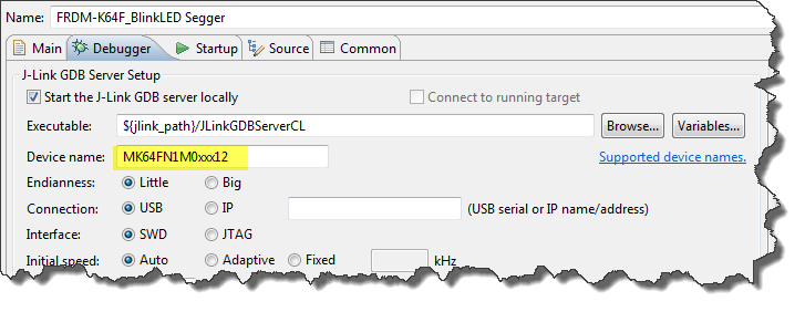
Device Name for Segger GDB Configuration
There must be an easier way for this? Yes, indeed, there is 🙂
For the GNU ARM tools it is easy to print out the code and date size information, see
But this is all for ARM cores. What if I use other architectures like S08 or ColdFire in Eclipse?

Code Size Information in Build Console
The existing OpenSDAv1 (see “OpenSDA on the Freedom KL25Z Board“) bootloader is using the industry standard Motorola S-Record (S19) Files. However, new FRDM-K64F board (see “FTF: FRDM-K64F, Kinetis Design Studio and Kinetis SDK“) has OpenSDAv2 on it, which is an mbed bootloader. So how to create files with an IDE other than mbed for that bootloader which is present on the FRDM-K64F board by default? Well, creating binary files is one thing, but to have it working with the mbed bootloader is another challenge :-(.

FRDM-K64F with mbed MSD bootloader
The new flagship of FRDM boards is the FRDM-K64F board. After FTF I have explored different ways debugging the board, and received many comments and questions about it (thanks!). Freescale announced the supports with the new Eclipse based Kinetis Design Studio (KDS). But until KDS is out, how can I use the FRDM-K64F board with CodeWarrior?

Debugging FRDM-K64F Board with CodeWarrior for MCU v10.6
The mbed for FRDM-K64F firmware (http://mbed.org/handbook/Firmware-FRDM-K64F) has great potential. Unfortunately it seems that edges are still very rough: It happens very often that my FRDM-K64F board gets locked up :-(. I can see that the target CPU is constantly resetting: the red reset LED is always on:
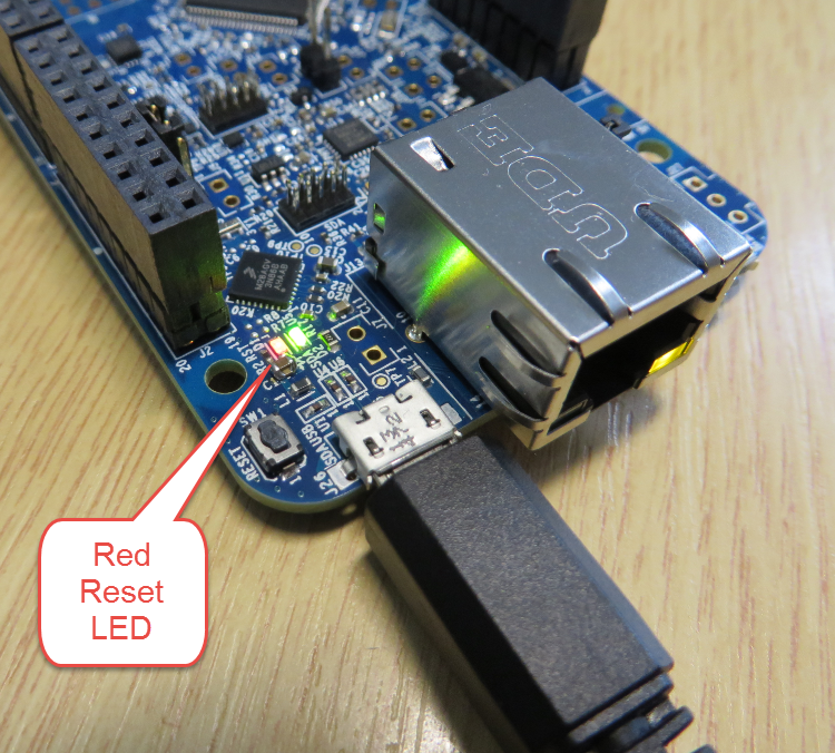
FRDM-K64F Red Reset LED always on
my students sometimes are afraid to ask questions, although I urge them ask any question. In my opinion there are no ‘dumb’ questions: only questioning things let us think and learn new things. I see that many readers of this blog are *not* afraid to comment or ask questions. The WordPress statistics shows 5’687 questions/comments for this blog (thank you all!), and the spam filter protected me from 202,341 items (ok, these *are* dumb) :-).
The ‘question of the week’ comes from Andy. That question caused me some serious head scratching, but the same time I have learned something important and useful for my next project: how to tell the ARM GNU linker *not* to initialize variables?

GNU ARM Embedded Linker Options
Many modern microcontroller have a cool feature: Pin Muxing. What it means is that I can ‘mux’ the pins for different purposes: such as I can use a SPI or I2C pin as GPIO (General Purpose Pin) or vice versa. In an ideal world, I would be able to ‘route’ or ‘mux’ pins freely around. In practice these ‘way switches’ are more or less limited.
In “Using the Reset Button on the Freedom Board as User Button” I muxed the FRDM-KL25Z reset pin as GPIO pin. The same approach can be used for muxing the NMI (Non-Maskable Interrupt) pin for the Freescale Kinetis devices. I’m showing it here how to do this with Processor Expert as this allows me to do this with a few mouse clicks.

NMI Pin Used as GPIO Pin
Eclipse is very powerful. To the point that you can do the same thing in multiple ways. I’m always learning new things, and recently I discovered a new way how to create a new launch or debug configuration.
So far I selected the item (e.g. GDB Hardware Debugging) and used the ‘New’ Icon:
New Debug Configuration with New Icon
I have been asked this question several times:
“How can I define my own interrupt vector with Processor Expert?”
So I think it deserves a short tutorial, if more than one person is asking this ;-).
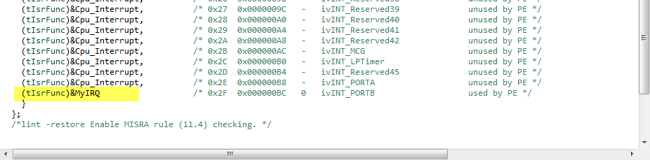
My user interrupt in the vector table
