
From my previous MetaClockClock project, I still had some hardware available. So I decided to build my largest build so far: to clocks with 78 clocks each.
Outline
A ‘MetaClockClock’ is a clock made of clock, arranged in a matrix organization. The hands of each clock can be controlled individually. That way, it can ‘draw’ text or orchestrate moving patterns.
You can find more about the hardware and build instructions in my previous articles, for example here: MetaClockClock Build Instructions. Sources and hardware files are available on GitHub: https://github.com/ErichStyger/MetaClockClock
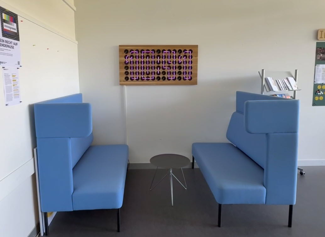
MetaClockClock with Oak Front Panel
My previous build (New MetaClockClock: Combining Art and Technology in Clocks) used the concept of an oak wood front panel with 60 clocks. I used the same idea for the front panel. But instead of a single clock, I have built two clocks with 78 units each.
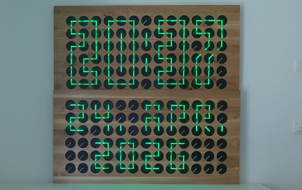
Because the clocks are using an RS-485 bus for communication, multiple clocks can be combined for a larger unit as shown below:
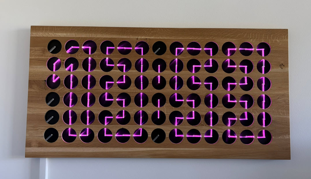
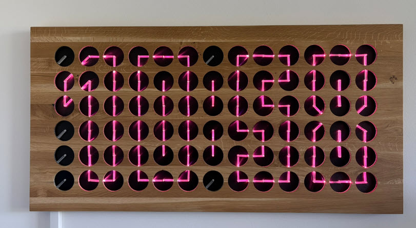
The MetaClockClock is Open Source and can display both animations and text:
Facts and Figures
Data for each of the two MetaClockClock78:
- Number of clocks:78 clocks with 360 degree dual shaft stepper motors
- Arrangement: 6×13 matrix
- Weight: 10.3 kg
- Size (WxH): 120 x 60 cm
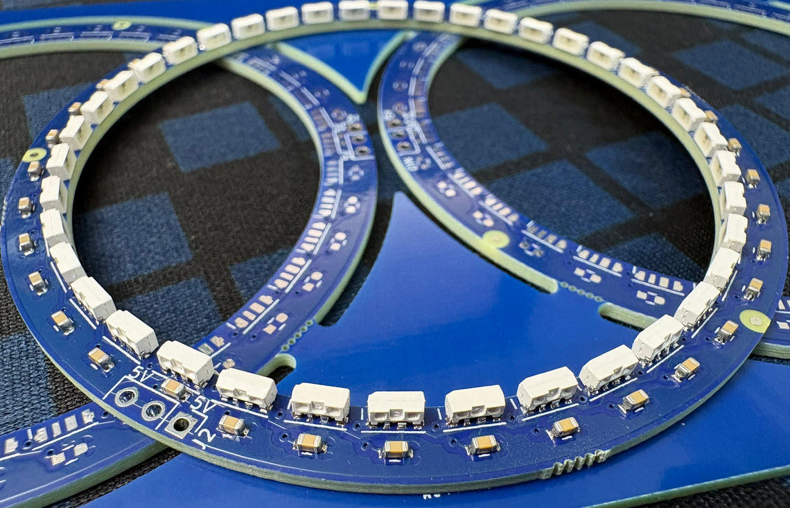
- LEDs: 3120 SK6812-Side LEDs, 40 for each clock
- PCBs: 78 clock PCBs plus 78 LED PCBs plus 1 RS-485 master
- Controller: NXP K02FN128
- CNC: 26 hours cutting time ((Shapeoko 4)
- CO2 Laser engraving and cutting for clock hands: around 60 minutes
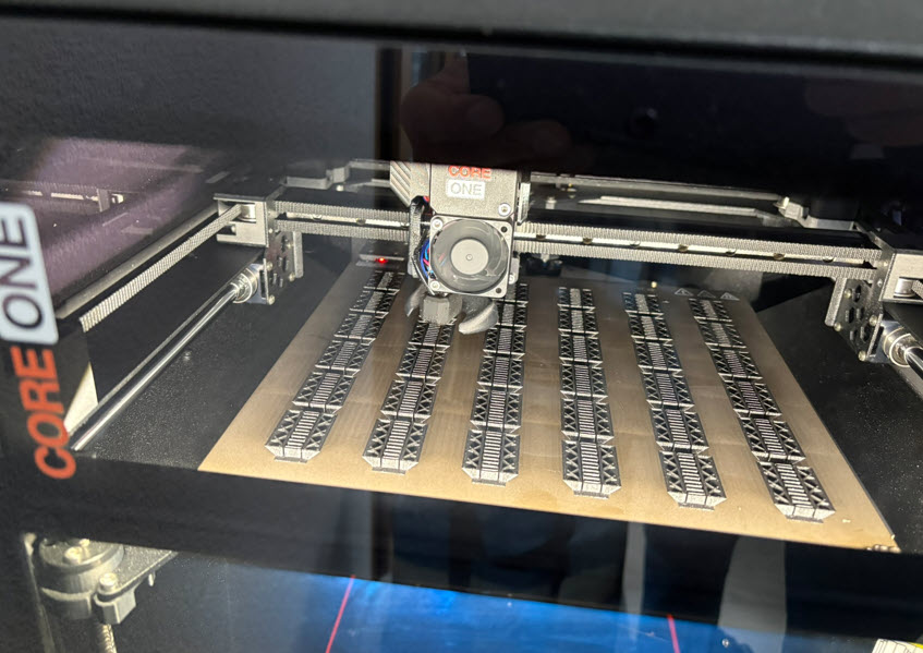
- 3D printing time: 52 hours (Prusa Core1)
- 3D printing material: 1 kg PLA
- Electronics BOM: 1500 USD (assembly/shipping not included)
Hardware
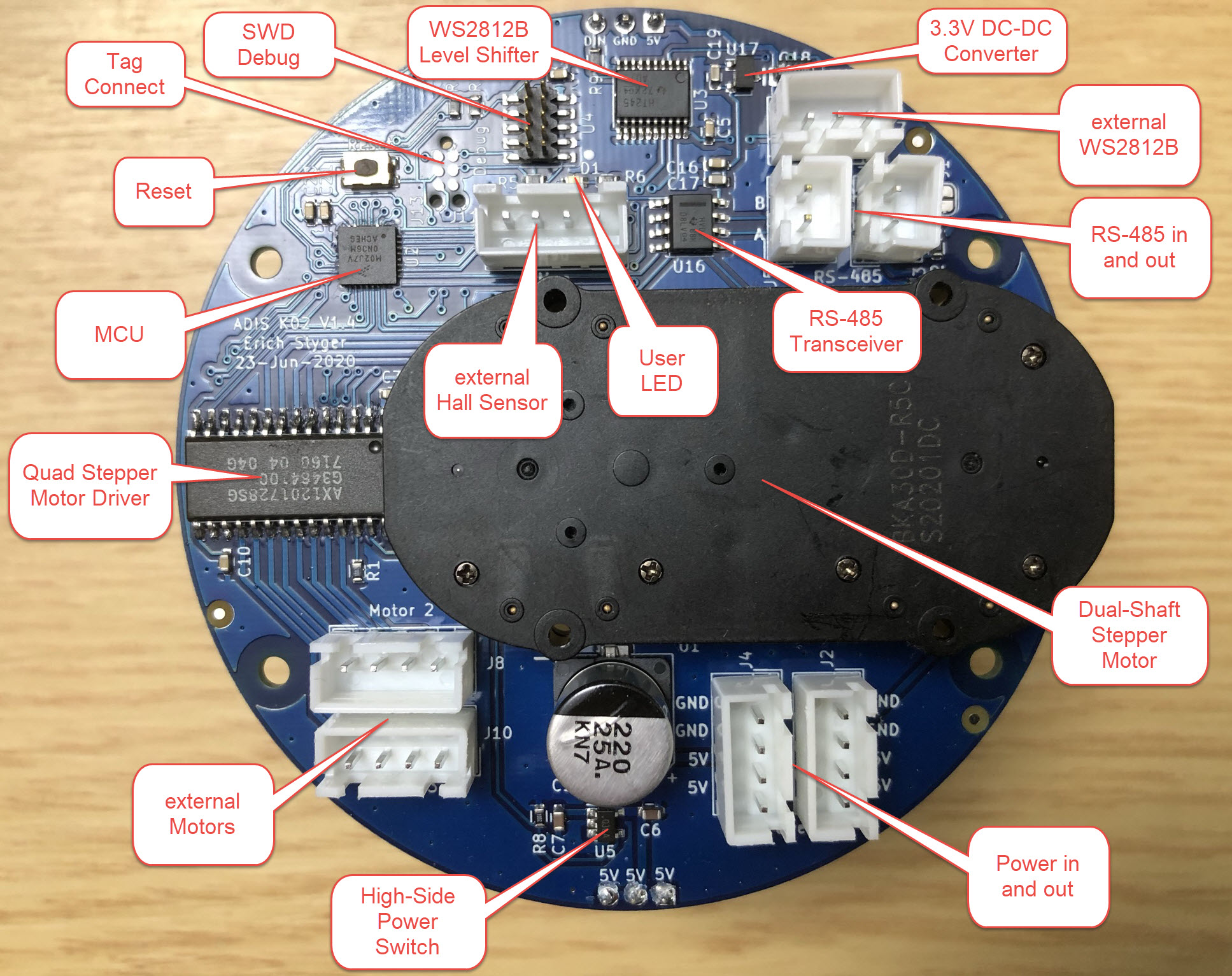
You can find details about the hardware design in MetaClockClock Build Instructions. The clocks use a combination of ‘MCU PCB’ and a ‘Motor PCB’:
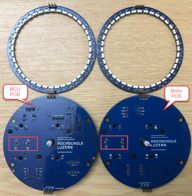
The ‘Motor PCB’ drives its own clock motor plus an extra one on the ‘Motor PCB’. Below the details of the ‘MCU board’:
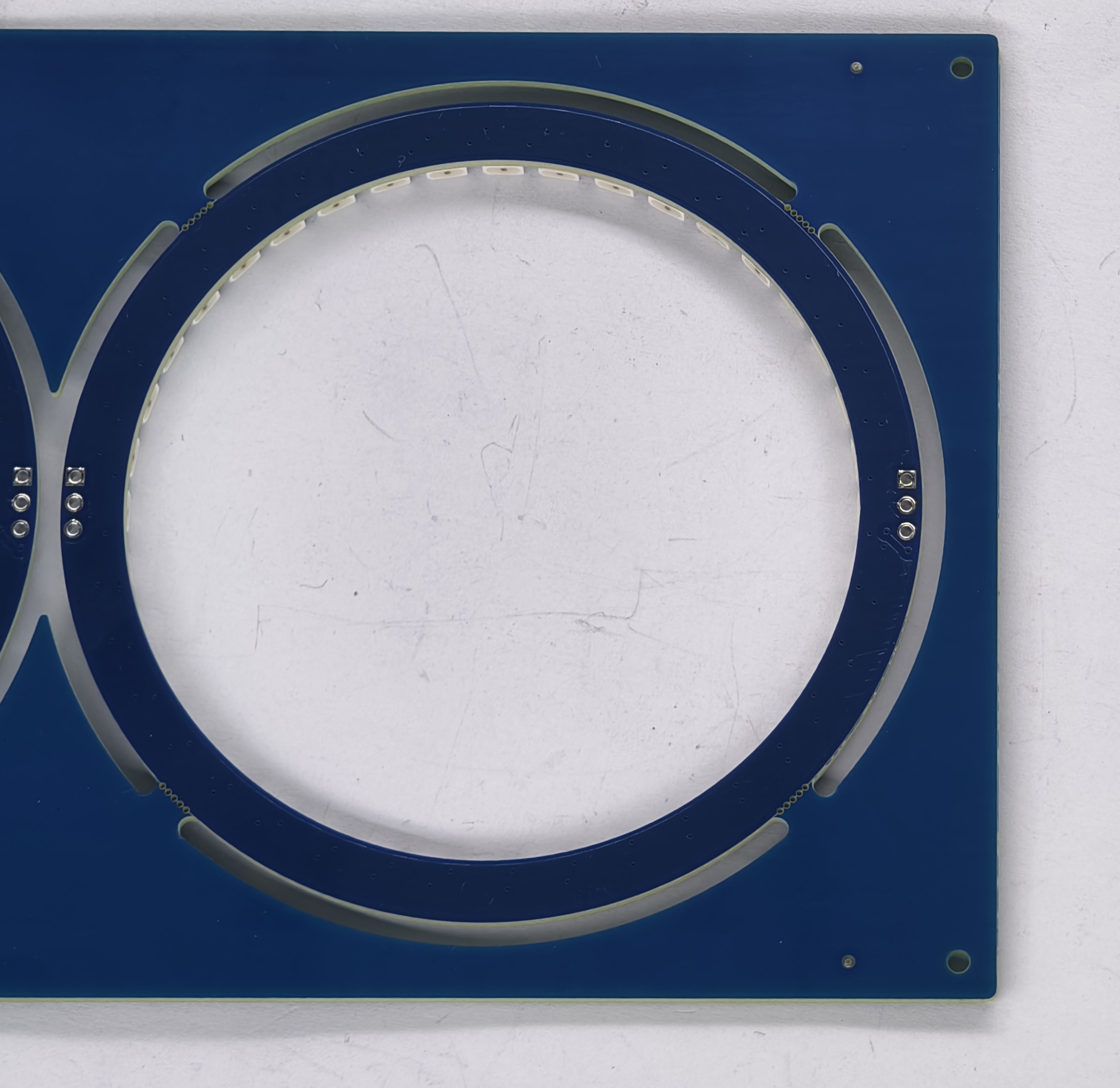
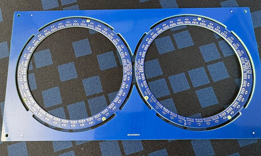
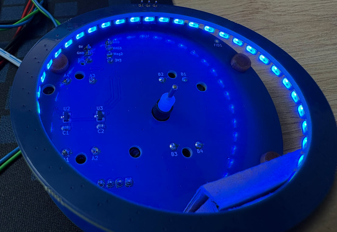
LED Ring PCBs and Assembly
I did not have enough LED rings for the second clock. So, I considered using our HSLU PCB SMD Pick&Place machine. During the semester, I don’t have much time and bandwidth. I reached out to PCBWay not only for the PCBs, but as well for assembly service.
The process is very simple: all what they need are the PCB files (Gerbers, position information) plus the BOM.
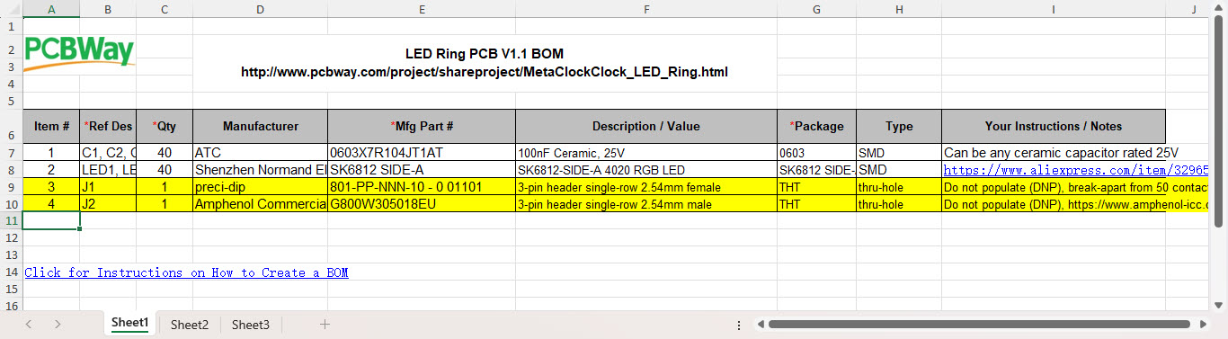
That was simple for me, as I already had this in place as shared project on PCBWay (https://www.pcbway.com/project/shareproject/MetaClockClock_LED_Ring.html).
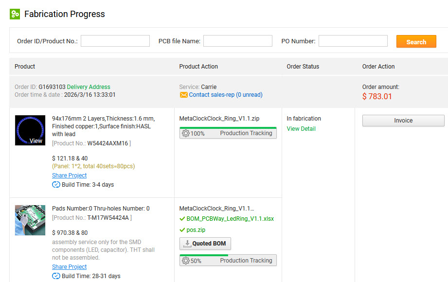
What I like is that I can follow the production status of my order on the web page.
PCBWay sent me images to check for component orientation, pin one alignment, and polarity. This way, I can check and give feedback before the full production run.
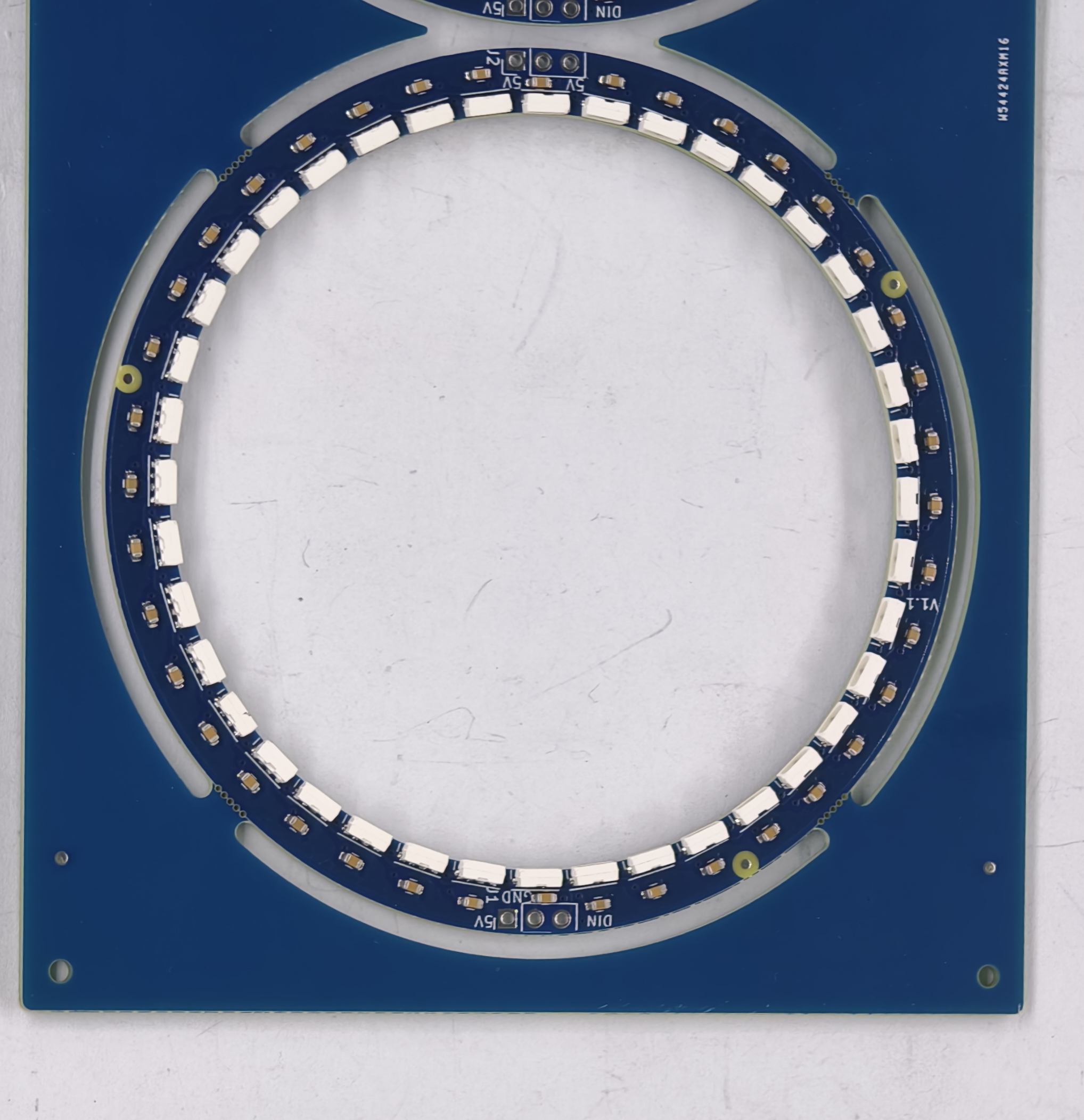
PCBWay packaged each LED ring into an ESD bag. In addition to that, they sent me some extra panels so I could use them populate more rings if needed.
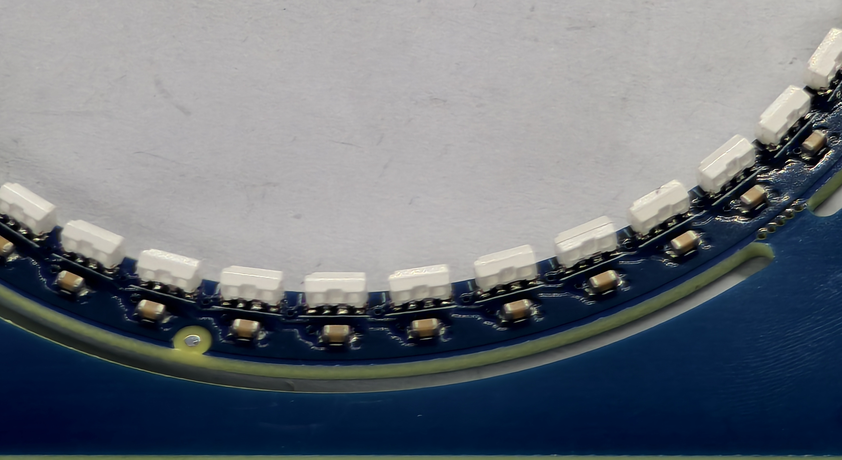
Visual inspection of the produced LED rings look fine,
PCBWay offered to test the assembled hardware, but I agreed to do it on my side. I used a simple test rig to test each of the 80 boards:
With such ‘blind’ assembly, there is a risk that some PCBs might need some rework. But in this case, every of the 80 PCBs worked without issues :-).
In retrospect: using PCBWay was the right decision and saved me a lot of assembly time.
Enclosure
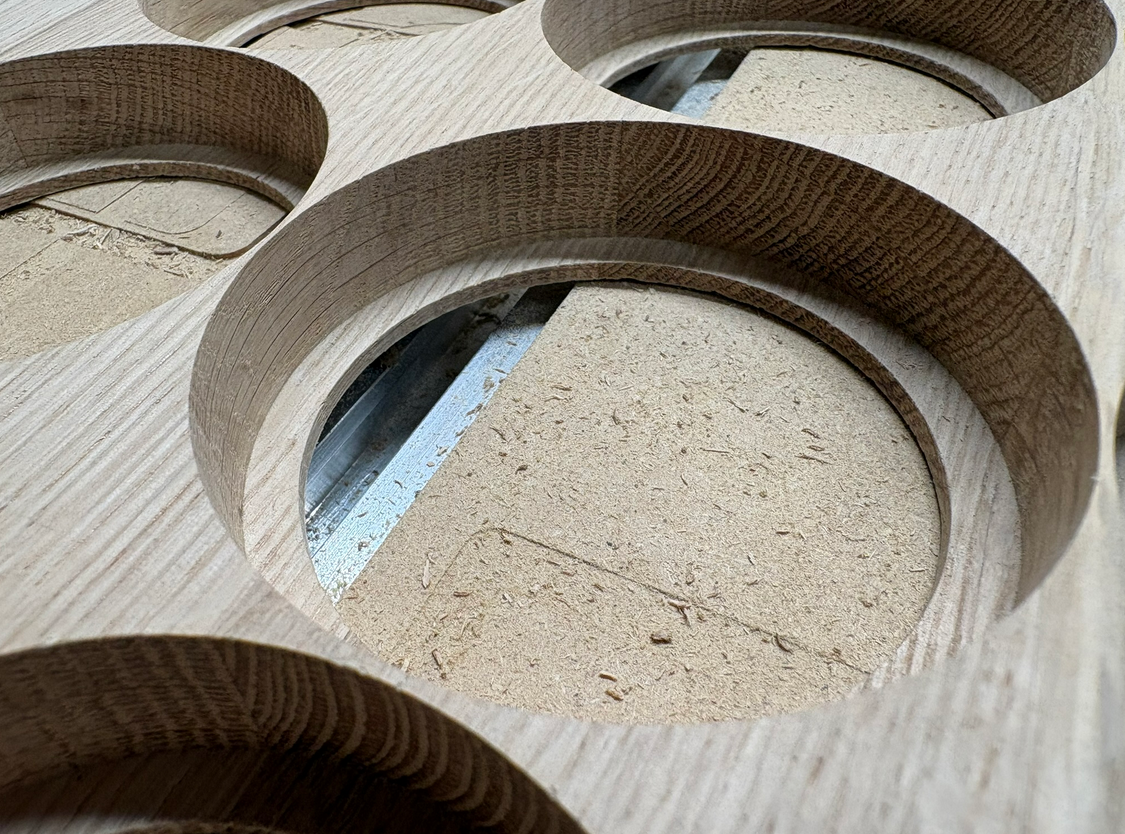
The front and enclosure is made of a 120x60x2 cm oak wood. Inserts for the clock has been cut with a Carbide3D Shapeoko 4 CNC machine.
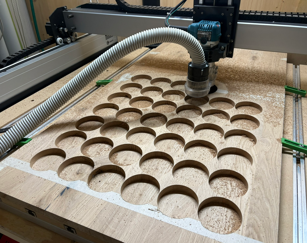
I only left 4 mm of wood for the LED rings to the front:
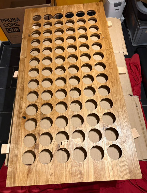
Each front panel had to be cut in two steps, because of the limits of the CNC cutting area.
After sanding, wood oil gave it the final look:
Wiring
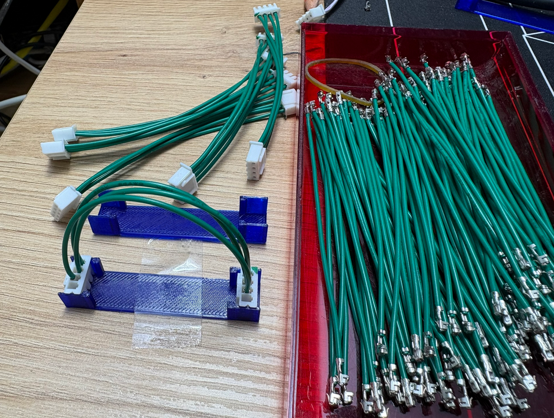
For the wiring and cables, I used pre-crimped wires, at least for most connections.
Below a view with the wiring on the back side:
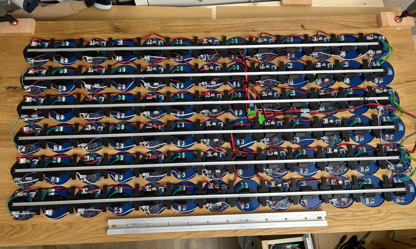
Clocks are connected on an RS-485 bus. For details see MetaClockClock Build Instructions.
Clock Mounting
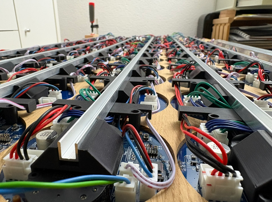
The clocks use a ‘press-fit’. U-shaped aluminum bars with 3D printed parts keep clocks an cables stored and aligned.
Everything is ‘press-fit’ without any screws for easy assembly and disassembly:
Software
Previous clocks used a 2×3, 3×5 or 4×5 font. For the new clock with 6 rows, a 3×6 font has been implemented:
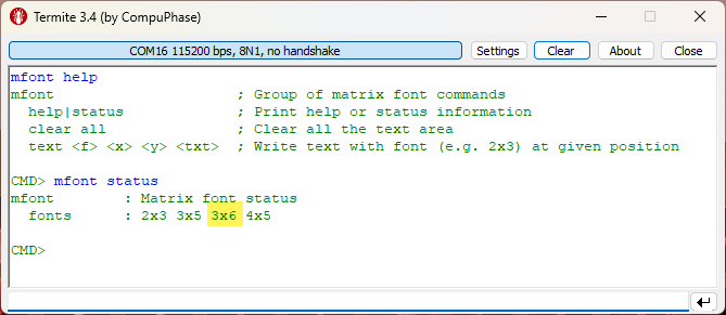
Because of the added column, I was able to add a ‘:’ separator for the time display:
Other than that, in the last months a lot of new features have been added:
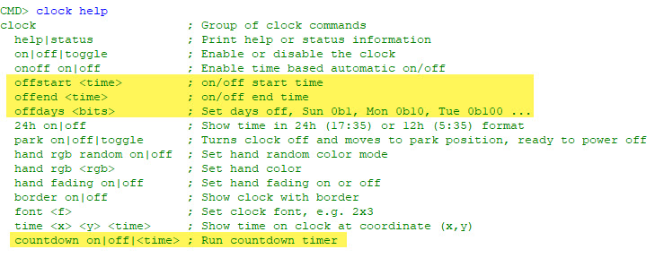
- Automatic daylight saving time switching
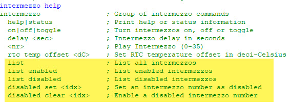
- Intermezzos can be individually enabled and disabled
- Clock can be turned off during night time or weekend days
- Clock with countdown mode
- Font characters can have proportional width
Videos
Below a few videos of the clock in action:
Summary
This has been my largest clock so far. And the biggest project to build two of them. The hardware has been proven from the previous clocks. But the total number and size has been challenging and time consuming. It took me 3 months from the beginning to the completion. Using PCBWay with assembly service for the rings of one clock was the right decision, it has saved me a lot of time. Software extension are working very fine with the MetaClockClock78. All the previous clocks are still supported too.
I probably won’t build another one. What I started with is integrating the clock into my home automation system (HomeAssistant). So that will be the next step and evolution.
If you want to build your own version: Hardware and Software is open source and available with the links at the end of this article.
Happy clocking 🙂
Links
- Previous project: New MetaClockClock: Combining Art and Technology in Clocks
- GitHub: https://github.com/ErichStyger/MetaClockClock
- Build instructions: MetaClockClock Build Instructions

Sehr cooles Projekt
LikeLike
Vielen Dank!
LikeLike