The new v0.5 MCU-Link-MR PCB (see MCU-Link-MR v0.5: Enhanced Debug Probe for ARM Cortex-M) comes with an extra pin header for logic analyzer signals. Because of this I have updated the enclosure for it:
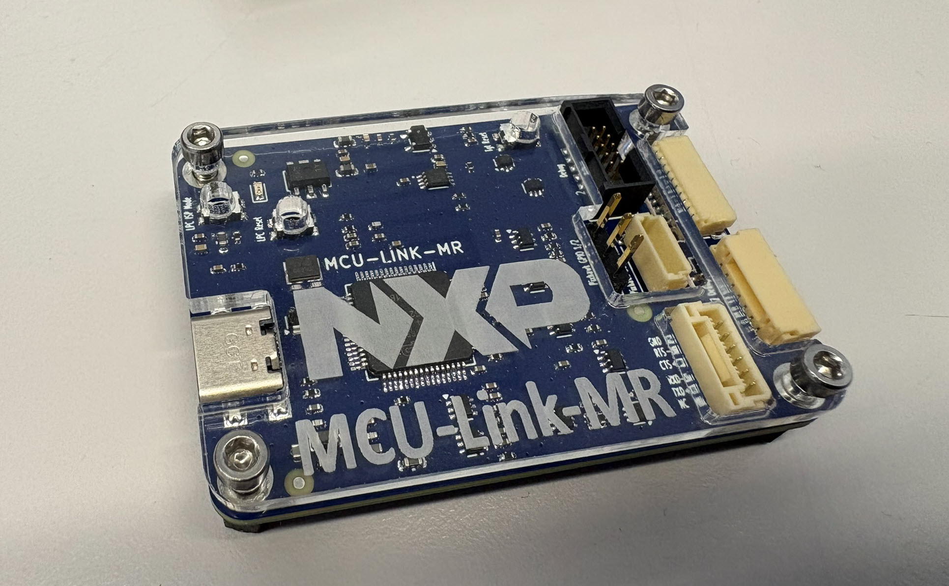

The new v0.5 MCU-Link-MR PCB (see MCU-Link-MR v0.5: Enhanced Debug Probe for ARM Cortex-M) comes with an extra pin header for logic analyzer signals. Because of this I have updated the enclosure for it:
With “Adding RGBW Wings and Enclosure to a Debug Probe” I have a really shiny enclosure for the MCU-Link Pro Enclosure.
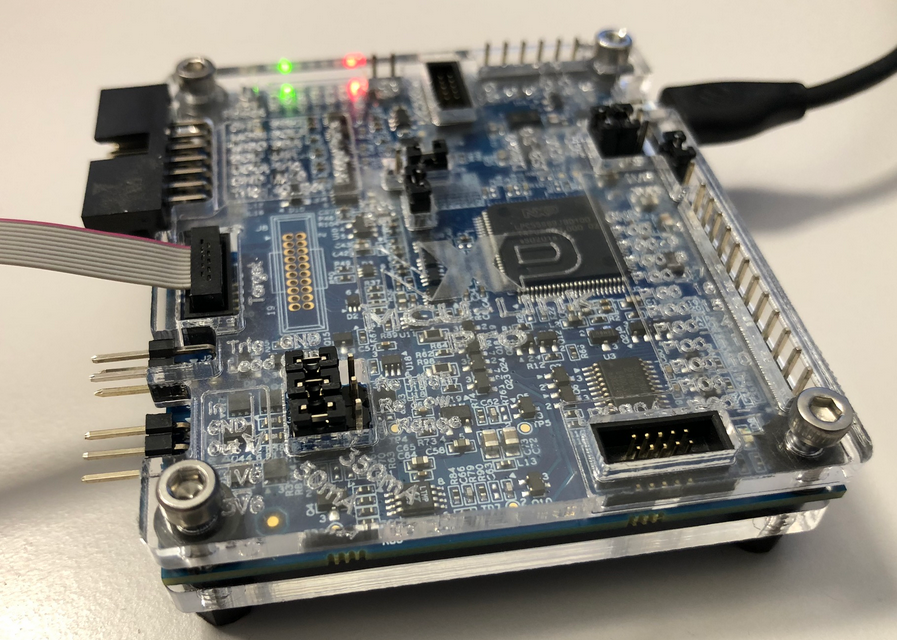
But I did not had enough time to replicate this for a full set of classroom hardware. The original card boxes from NXP showed already after one semester severe wear, so I have to setup something more robust: a box to store all the cables, and an enclosure to protect the PCB, for 40 units.
3D printing would take to much time, so I ended up with buying storage boxes and creating an laser-cut acrylic (PMMA) enclosure for the debug probe itself:
Tomorrow is the 1st Advent, and right on time I was able to finish a special version of an Advent calendar for the Christmas 2020:
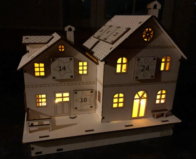
laser cut advent calendar illuminated
Human since 1982 claims
“Human since 1982 have the copyright to works displaying digital time using a grid arrangement of analog clocks…”
I’m not a lawyer, but without obligations (imho) I have removed the content.
You can read more of the details here: Copyright Law for Makers and Educators
Thanks for understanding,
Erich
Having access to a laser cutter makes it possible to design custom enclosures. This one is for a Raspberry Pi in a Steampunk design:

Steampunk Enclosure
For this Christmas time I wanted to create a special gift box for a special neighbor family.

Christmas Gift Box Wrapped
Need a quick way how to attach a LED, a push button and two resistors to the Raspberry Pi header? One way is to use some ‘flying’ wires. Or to use three pieces of lasercut plywood for a nice looking Raspy extension board:

Wood Circuit Board on Raspberry Pi
After all the 3D printing and laser cutting for a Pick&Place project, my laser cutter had something else to do this Easter weekend:
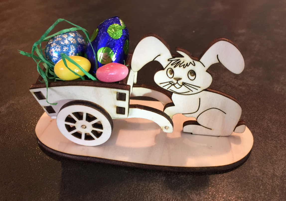
Happy Easter
