
Question: What to do on a rainy Sunday?
Answer: Having fun with USB and the KL25Z Freedom board! :-).
In “A shell for the Freedom board” I used the UART-to-USB OpenSDA capability of the KL25Z Freedom board: The KL25Z processor uses the OpenSDA K20 microprocessor as Serial-to-USB converter. But this only works because of the P&E OpenSDA USB CDC (Communication Device Class) implementation. If I create my board without OpenSDA, I need a different approach: I want to do USB CDC with the KL25Z :twisted:.

USB CDC Device on COM22
For several months I’m using successfully my Processor Expert FSL_USB_CDC component since early this year, in several projects and with different boards. What is missing is support for the Kinetis KL25Z. So this is what this tutorial is about. It takes you maybe around 30 minutes, and you will have USB support with your Freedom board :-). As for myself, after learning all the knowledge needed, it takes me less than 10 minutes :grin:.
I’m using CodeWarrior for MCU10.3 with my Processor Expert components. If you followed my earlier Freedom Board tutorials, then I hope you are familiar with loading more user components. Otherwise, have a look at the section “Additional Processor Expert Component Installation” in this post. In this tutorial I’m using following components:
- FSL_USB_Stack: Freescale USB Stack as Processor Expert component.
- Wait: Universal realtime waiting functions.
- Optional: LED: Universal LED driver.
❗ The FSL_USB_Stack Processor Expert component has been updated to version V1.008 to support the KL25Z
Step 1: Creating the Project (or reuse an existing one)
In this tutorial I start from a clean sheet and create a new project. Of course it is possible to add USB CDC support to any of the other tutorials I have published for the Freedom KL25Z board, e.g. Tutorial: Enlightening the Freedom KL25Z Board. In that case, you can skip this step.
To create a new project, I select the menu File > New > Bareboard Project and give it a project name:

New Bareboard Project
Next is to select the device:

Selecting Device
I’m going to debug the board with OpenSDA only, so I deselect the default P&E Multilink, and select Open Source SDA:

OpenSDA Selection
The next dialog is about the language and build tools options: I go with the defaults:

Language and Build Tools Options
In the next dialog I make sure I select Processor Expert:

Processor Expert Project Option
Pressing Finish will create the project:

Project created
💡 Hint: In case the extra Processor Expert views are not already open: I use the menu ‘Processor Expert > Show Views’.
Step 2: Adding the Components
The next step is to add my other component(s): I select the component(s) in the Components Library view and add it to my project. If I already have the Wait component in my project, of course no need to add it again.

Selecting and Adding Components
This will add the components to my project. And the USB component shows a red (x) telling me that it needs to be configured:

Need to configure the FSL_USB_Stack
I need to component Inspector to configure the properties.
💡 The context menu ‘Inspector’ on a component opens the Component Inspector View.
If I inspect the properties of the USB component, it shows me that I need to set up the CPU and the USBInit property:

Need to configure component
So I select the CPU for my KL25Z board, and select Init_USB_OTG_VAR0 to initialize the USB peripheral for it:

USB component configured for KL25Z
❓ No idea why Freescale has decided to name that Kinetis component as ‘Init_USB_OTG_VAR0’. A name like ‘Init_USB_OTG_Kinetis’ would have been *much* easier to use and remember.
The USB CDC stack is using two ring buffers:
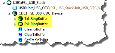
USB Ring Buffers
Make sure that the buffers (Rx and Tx) has enough buffers specified. Recommended is a minimum size of 32 bytes:
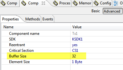
Ring Bufffer Size
The next thing is to inspect the USBInit component. And it is good to pay close attention to the warnings:

Warnings in USBInit
Enabling the Clock gate ensures that the USB module is clocked. And as I have no external clock pin, I select to use the PLL/FLL clock source:

Enabled Clock Gate and configured clock source
The inspector informs me about a very important thing: the USB module requires a 48 MHz clock. So I need to make sure that this is configured properly.
❗ Warning: Failing to configure the USB clock properly is probably the most common source of failure. For myself I can count endless hours debugging and inspecting my projects, and in many cases I made a mistake in the clock configuration. Unlike many other USB enabled devices, the Freescale ones need an external crystal, and that crystal has to be used to generate a very stable and accurate clock signal. Otherwise it will *not* work.
Step 3: Configuring the Clock
According to the FRDM-KL25Z Schematics (SPF-27556_D).pdf have a 8 MHz crystal on the board:

8 MHz Crystal on FRDM-KL25Z
❗ IMPORTANT: I’m using in this post the ‘white’ pre-production Freedom Board. The black production board board has several differences (see Completing the FRDM-KL25Z Board). An important difference is that the black board has the 1.0MOhm resistor R25 nearby the 8 MHz: with that resistor *not* populated, the clock will *not* run in high gain mode. So for the black Freedom board with that resistor *not* populated, the clock mode has to be in ‘low power’ mode.
The configuration of the clock is in the CPU component. For this I select the CPU to configure the properties:

CPU component to configure the clocks
I can have multiple oscillator settings, but here I just need one. So I enable the ‘System oscillator 0’ setting, and configure it to use an 8 MHz external crystal in High gain mode (for the white pre-production board which has the R25 (see above) populated, but in Low Power mode for the black production board:

Setting 8 MHz external crystal with High Gain (White board only!!!)
As the black Freedom board has no R25 populated, the Oscillator operating mode has to be ‘Low power’ instead:
")
Low Power Oscillator Mode required if R25 not populated (black Freedom board)
Next is to select the PEE (PLL Engaged External) clock mode: in this mode, the PLL is using the external reference clock. Remember that the USB block needs an 48 MHz PLL signal? So I need to configure it to 96 MHz as it will be divided by a factor of 2 until it reaches the USB block:

PEE MCG Mode
With my clock changes, the core clock is not set correctly:

Error for core clock
With my base clock of 8 MHz, I can set the CPU core clock to 48 MHz and a Bus clock of 24 MHz:

Core and Bus Clock
Now I could think that everything is just fine. But there is one possible glitch, and maybe this is even a silicon problem (?): I need to *disable* the Internal and External reference clock, otherwise my board will crash during clock configuration. So I need to *disable* the reference clocks:

Internal and External Reference Clock disabled
Checking my USB module again, it shows that it is now properly clocked with 48 MHz:

USB with 48 MHz PLL clock
😕 Processor Expert still warns about the need for 48 MHz clock, even I have it set up with 48 MHz? Anyway, the important thing is that it *is* clocked with 48 MHz.
Step 4: Adding Application Code
I keep things very simple here: no RTOS. All what I add in Processor Expert is a simple loop-back which does an echo of what I type into the terminal window.
To show the current enumeration status, I’m using my code from my earlier Tutorial: Enlightening the Freedom KL25Z Board.
❗ Hint: An easy way to copy Processor Expert components from one project to another is using copy-paste. If you do not want to use the LEDs, then simply remove the code for the LEDs in the code below.
I’m adding the function CDC_Run() to the ProcessorExpert.c as below and call it from main():
Note: Later version of the component is using CDC1_ Prefix for functions, as the methods have been moved to a separate CDC submodule.
/** ###################################################################
** Filename : ProcessorExpert.c
** Project : ProcessorExpert
** Processor: MKL25Z128VLK4
** Version : Driver 01.01
** Compiler : GNU C Compiler
** Date/Time: 2012-10-07, 12:33, # CodeGen: 0
** Abstract :
** Main module.
** This module contains user's application code.
** Settings :
** Contents :
** No public methods
**
** ###################################################################*/
/* MODULE ProcessorExpert */
/* Including needed modules to compile this module/procedure */
#include "Cpu.h"
#include "Events.h"
#include "WAIT1.h"
#include "USB1.h"
#include "USBInit1.h"
#include "Tx1.h"
#include "Rx1.h"
#include "LED1.h"
#include "LED2.h"
#include "LED3.h"
#include "GPIO1.h"
#include "GPIO2.h"
/* Including shared modules, which are used for whole project */
#include "PE_Types.h"
#include "PE_Error.h"
#include "PE_Const.h"
#include "IO_Map.h"
/* User includes (#include below this line is not maintained by Processor Expert) */
static uint8_t cdc_buffer[USB1_DATA_BUFF_SIZE];
static uint8_t in_buffer[USB1_DATA_BUFF_SIZE];
static void CDC_Run(void) {
int i;
for(;;) {
while(CDC1_App_Task(cdc_buffer, sizeof(cdc_buffer))==ERR_BUSOFF) {
/* device not enumerated */
LED1_Neg(); LED2_Off();
WAIT1_Waitms(10);
}
LED1_Off(); LED2_Neg();
if (CDC1_GetCharsInRxBuf()!=0) {
i = 0;
while( i<sizeof(in_buffer)-1
&& CDC1_GetChar(&in_buffer[i])==ERR_OK
)
{
i++;
}
in_buffer[i] = '\0';
(void)CDC1_SendString((unsigned char*)"echo: ");
(void)CDC1_SendString(in_buffer);
(void)CDC1_SendString((unsigned char*)"\r\n");
} else {
WAIT1_Waitms(10);
}
}
}
/*lint -save -e970 Disable MISRA rule (6.3) checking. */
int main(void)
/*lint -restore Enable MISRA rule (6.3) checking. */
{
/* Write your local variable definition here */
/*** Processor Expert internal initialization. DON'T REMOVE THIS CODE!!! ***/
PE_low_level_init();
/*** End of Processor Expert internal initialization. ***/
CDC_Run();
/*** Don't write any code pass this line, or it will be deleted during code generation. ***/
/*** RTOS startup code. Macro PEX_RTOS_START is defined by the RTOS component. DON'T MODIFY THIS CODE!!! ***/
#ifdef PEX_RTOS_START
PEX_RTOS_START(); /* Startup of the selected RTOS. Macro is defined by the RTOS component. */
#endif
/*** End of RTOS startup code. ***/
/*** Processor Expert end of main routine. DON'T MODIFY THIS CODE!!! ***/
for(;;){}
/*** Processor Expert end of main routine. DON'T WRITE CODE BELOW!!! ***/
} /*** End of main routine. DO NOT MODIFY THIS TEXT!!! ***/
/* END ProcessorExpert */
/*
** ###################################################################
**
** This file was created by Processor Expert 10.0 [05.03]
** for the Freescale Kinetis series of microcontrollers.
**
** ###################################################################
*/
❗ It is important that the application calls App_Task() frequently, because with this routine data is sent and received.
Step 5: Running the Application
Now I can generate code for my drivers, e.g right click on the ProcessorExpert.pe file and selecting ‘Generate Processor Expert Code‘:

Generate Processor Expert Code
followed by building the sources (menu Project > Build Project). And then download/debug it.
With the USB plug disconnected, the red LED is on:

USB disconnected: red LED on
With connecting the USB cable to the KL25Z, it enumerates the device and the green LED is on:

USB enumerated: green LED on
Additionally it has been enumerated as device on my host machine:
Freescale CDC Device
In case it is the first time you use such a CDC device: the driver .inf file is generated in the ‘Documentation’ folder (for details see USB CDC, reloaded):

cdc.inf driver files
I connect to the virtual CDC COM port with a terminal program. And the application will echo what I send to it:

Terminal Connection with Echo
Summary
Setting up and using a USB stack is definitely not a trivial task, as a lot of settings needs to work correctly. I hope that with the above information it should be much easier to do this now for the Freescale FRDM-KL25Z board. Using Processor Expert makes things definitely a lot easier. While the above project is bare-metal (no RTOS), it is easy to add an RTOS to it. That’s actually how I use it like in the Freedom Shell project.
The above project can be downloaded here or from the link on http://www.steinerberg.com/EmbeddedComponents/Examples/Examples.htm
Happy USB Freedom 🙂

Another excellent tutorial, thank you. I have saved this into One Note so I can reference it when I set up your USB/Fatfs components with the K20.
You mentioned in the point on disabling the reference clocks (I did not know this either), similar to this point regarding the clocks, I noted that there are external capacitors to ground on the KL25Z clock circuit. I spent a lot of time trying to get our k20dx256 custom board to sync on the clock and it wouldn’t, because we had put these same capacitors in the k20 clock circuit during layout. A mistake in design on my side because I had used the wrong reference design… a fatal error. Everyone would not make that mistake, but it is very important to check the clock circuit because some silicon like the coldfire and some Kinetis processor use these cap’s, others do not. It can waste a lot of time.
LikeLike
Hello.
I am having trouble setting the buffers for the FSL_USB_Stack component. The message “No inherited component assigned” appears on the “Send Buffer” and “Receive Buffer” lines on the “Details” column. When I open the drop-down menu, the item “Buffer” appears, I select it but it doesn’t stay selected, it disappears immediately and properties stay marked as errors.
When I started creating the project I had not installed the USB stack from Freescale. I installed it midway through the steps. I thought that might the problem, so I closed and reopened CodeWarrior but the problem persists.
I can see from your screenshots that you don’t have this problem. Do you have any idea why this is happening?
Thanks.
LikeLike
This sounds like you have not loaded the RingBuffer component? Have you installed this one http://www.steinerberg.com/EmbeddedComponents/RingBufferUInt8/home.htm ?
Hope this helps,
Erich
LikeLike
hi Erich,
Thanks for this wonderful post. After doing all exercises my code is working fine but after close codeworrier, my problem start. When i reopen this project, during import this project i get following error.
Error
Length of selected text is below required minimul length: 16 charcter (Bus reported Device)
Length of selected text is below required minimul length: 28 charcter (Bus reported Vendor)
Please guide.
Regards
anand Kalode,.
LikeLike
Hi anand,
This looks like a bug Processor Expert introduced a while back, which I have fixed with a workaround in my components. Can you confirm that you are using the latest components from SourceForge (see https://mcuoneclipse.com/2014/10/21/mcuoneclipse-releases-on-sourceforge/) as it seems to me that you are using older files?
Erich
LikeLike
Hi there.
Me again. I finally got to debugging, but when I click the button, the screen changes to the Debug Perspective but nothing happens. Focus is given to the Console window in the bottom but with nothing written on it.
On the Debug Window on the top there is a line that reads “Thread [ID: 0x0] (Running)”. Usually when the programming is finished and debugging is ready to start, the ProcessorExpert.c code is displayed, but it’s not.
Do you have any idea on what might be the cause?
Thanks.
LikeLike
Looks like the debugger is running, but did not reach main(). Could you suspend/pause the debugger to see where you are? Maybe it loops within the clock set-up? This would mean that your clock settings are not correct.
LikeLike
Hello.
Yeah. Looks like it’s stuck in line 126 of Cpu.c, it reads:
while((MCG_S & MCG_S_IREFST_MASK) != 0x00U) { /* Check that the source of the FLL reference clock is the external reference clock. */
}
On my CPU component settings, the MCG is in PEE mode, and according to the pop-up that comes up when you hover over the settings, in PEE mode the FLL is disabled in a low-power state, and it is, in fact, marked as Disabled in the Component Inspector.
Any idea why this is?
Luis.
LikeLike
I downloaded your project source files and copied them to my workspace, built the configuration and started the debugger, and the debugging stops at the same line. I can see from your screenshots that didn’t happen to you.
Also, I read in this post that there’s a problem when debugging with JTAG, but I don’t think that’s the case here, is it? Although they reference the same line in the code.
LikeLike
I tried using the MSD SDA application, so as to not use the debugger, and copying the hex file geterated into the FRDM-KL25Z drive but that didn’t work either.
LikeLike
Have you reprogrammed the firmware application on the board as shown in https://mcuoneclipse.wordpress.com/2012/09/20/opensda-on-the-freedom-kl25z-board/?
What error message (if any)?
LikeLike
Yeah.
I’m using the latest version that comes in the Quick Start package, DEBUG-APP_Pemicro_v102.SDA and MSD-FRDM-KL25Z_Pemicro_v105.SDA.
There are no error messages, neither when programming through MSD nor the debugger. Through MSD nothing happens (I believe the red LED is supposed to light on when there is no USB detected, and the green when there is), and in the debugger, the code stops at the line previously mentioned.
It’s strange this doesn’t happen to you.
LikeLike
Really interesting. It works for me on the white preproduction board as shown in my blog. But I can reproduce what you say with the black production board. Looking closer at the black board, I see that the 1 MOhm R25 resistor between crystal and microcontroller is *not* populated on the black board. No clue why. But this could be the reason for the failure. I don’t have a resistor at hand, but I bet if you would solder that resistor onto the board, it will work. I check if there is something I could change in the Processor Expert settings to overcome this.
LikeLike
Yep.
I see it now. That’ll show me to look everywhere for issues, not just software. I’ll try to get a hold of that 1 MOhm resistor as well, and i’ll let you know.
Hope you find a software workaround for this. I’ll be checking back for updates in case you do. I’ll give it a shot too.
Thanks for the help.
LikeLike
I have found the solution! In the CPU component, under Clock Settings > System oscillator 0 > Clock Source > Oscillator operating mode, change the settings from high gain to ‘low power’. I will update the post with that information.
LikeLike
Hey!!
That’s great news!!
Will try it as soon as I get back to the lab. I’ll let you know.
Thanks again.
LikeLike
Hello.
Just writing back to let you know that it worked great.
Thanks for everything.
Luis.
LikeLike
Hello.
Just writing back to let you know that yesterday I received a new FRDM-KL25Z board and that one DOES come with the R25 1MOhm resistor soldered. They are both of the blue board kind, NOT the white.
So maybe it was just a certain batch of boards that didn’t get that resistor assembled. I’ll write an email or something to Freescale just to let them know and get some answers as to what happened there, just to know.
Anyways, just wanted to let you know.
Luis.
LikeLike
Yes, I have found out the same: at least one black board which I have ordered has the R25 populated as well, and I have informed Freescale already about this.
LikeLike
Pingback: Completing the FRDM-KL25Z Board | MCU on Eclipse
I have secured my device and now is showing “Device Secured ! Erase to Unsecure ?” I click yes but the problem continues ! I have tried with OpenSDA and P&E Multilink FX debugger and the result remains the same ! What to do to unsecure device ?
LikeLike
Have you enabled the ‘disable mass erase’ bit on the device? If so, then you are doomed, as you cannot recover the device. As for myself: I’m able to recover with that dialog my devices which are secured. It would be interesting to know what you did? Are you using the external clock? Maybe your board is damaged?
LikeLike
Pingback: Using the 8 MHz Crystal on the FRDM-KL25Z Freedom Board | MCU on Eclipse
Hello Erich
I followed both examples:
Tutorial: A Shell for the Freedom KL25Z Board
Tutorial: USB CDC with the KL25Z Freedom Board
II tried to combine the two examples, but I could not get it to work
Can you put on your list an example that links the two tutorials in order to transmit from a usb and receive from the other and vice versa ,obviously with FreeRTOS?
Thanks
Carlo
LikeLike
Pingback: USB CDC and SCI: Side-by-Side with the Freedom Board | MCU on Eclipse
Hello Erich,
after updating the component FSL_USB_Stack from 1.008 to 1.010 the project (Freedom_UsbCdc) does not build. With version 1.008 all is fine, but the echo is char by char and not as your screenshot (https://mcuoneclipse.files.wordpress.com/2012/10/terminal-connection-with-echo.png) show.
The error is first:
– CPU (under CDC1:FSL_USB_CDC_Device): No value selected
->> After choosing Kinetis KL25 (my FRDM-KL25Z board) the errors are:
Description Resource Path Location Type
FAILURE: at line 2: Command %set cannot be used in this type of script. It can be used in component script only. (file: Beans\FSL_USB_Stack\FSL_USB_Stack.chg) Freedom_UsbCdc Processor Expert Processor Expert Problem
FAILURE: at line 25: Command %set cannot be used in this type of script. It can be used in component script only. (file: Beans\FSL_USB_Stack\FSL_USB_Stack.chg) Freedom_UsbCdc Processor Expert Processor Expert Problem
FAILURE: at line 26: Command %set cannot be used in this type of script. It can be used in component script only. (file: Beans\FSL_USB_Stack\FSL_USB_Stack.chg) Freedom_UsbCdc Processor Expert Processor Expert Problem
FAILURE: at line 27: Command %set cannot be used in this type of script. It can be used in component script only. (file: Beans\FSL_USB_Stack\FSL_USB_Stack.chg) Freedom_UsbCdc Processor Expert Processor Expert Problem
FAILURE: at line 4: Command %set cannot be used in this type of script. It can be used in component script only. (file: Beans\FSL_USB_Stack\FSL_USB_Stack.chg) Freedom_UsbCdc Processor Expert Processor Expert Problem
FAILURE: at line 5: Command %set cannot be used in this type of script. It can be used in component script only. (file: Beans\FSL_USB_Stack\FSL_USB_Stack.chg) Freedom_UsbCdc Processor Expert Processor Expert Problem
FAILURE: at line 6: Command %set cannot be used in this type of script. It can be used in component script only. (file: Beans\FSL_USB_Stack\FSL_USB_Stack.chg) Freedom_UsbCdc Processor Expert Processor Expert Problem
FAILURE: at line 7: Command %set cannot be used in this type of script. It can be used in component script only. (file: Beans\FSL_USB_Stack\FSL_USB_Stack.chg) Freedom_UsbCdc Processor Expert Processor Expert Problem
FAILURE: at line 8: Command %set cannot be used in this type of script. It can be used in component script only. (file: Beans\FSL_USB_Stack\FSL_USB_Stack.chg) Freedom_UsbCdc Processor Expert Processor Expert Problem
FAILURE: at line 9: Command %set cannot be used in this type of script. It can be used in component script only. (file: Beans\FSL_USB_Stack\FSL_USB_Stack.chg) Freedom_UsbCdc Processor Expert Processor Expert Problem
mingw32-make: *** [Freedom_UsbCdc.elf] Error 1 Freedom_UsbCdc C/C++ Problem
undefined reference to `USB1_App_Task’ ProcessorExpert.c /Freedom_UsbCdc/Sources line 47 C/C++ Problem
undefined reference to `USB1_GetChar’ ProcessorExpert.c /Freedom_UsbCdc/Sources line 56 C/C++ Problem
By the way, thank you very much for this awesome article.
Regards,
Juan
LikeLike
Hello Juan,
yes, these error messages seems to be a problem with the MCU10.3 beta. The good news is that the workaround is very simple: close the project (menu Project > Close) and re-open it again, and the error should go away with the next code generation.
Thanks,
Erich
LikeLike
thank you, it worked.
Regards,
Juan
LikeLike
Hello Erich,
I have been trying to follow the above tutorial. However, I have not been able to find the “FSL_USB_Stack” component in “USB_STACK_V4.0.3.zip” or “.2”.
Somewhere I found “FSL_USB_Stack_1.010_15.11.2012.PEupd”. I am able to import this into my component library, but it can’t be installed into any project.
Do you know where I might be able to find the solution to this problem?
Thank you.
LikeLike
I figured out the answer to the above. It was one of those “You didn’t look carefully enough” questions.
Nevertheless, as described in my post, I still cannot include “FSL_USB_Stack” into my project from PE Component Library.
Do you have any suggestions I might try?
Is there any way to use any of the other USB components in the above tutorial instead of FSL_USB_Stack?
Thank you.
LikeLike
Not sure what the problem is. But maybe you could try the project from http://www.steinerberg.com/EmbeddedComponents/Examples/FreedomBoard/Freedom_UsbCdc.zip ?
LikeLike
My terminal output:
echo: Hey Erich, check this out!
echo: Program works
echo: Thanks again for your contribution
Thanks!
Rich.
By the way, Codewarrior 10 has a nifty terminal built into it so there’s no need for external programs anymore, which is pretty cool. It’s become my new favorite terminal program since it makes changing serial settings on the fly really easy to do. The view is normally hidden, but to access it, if interested, you can go to: Window –> Show View –> Other… –> Terminal
LikeLike
Hi Richard,
yes, I’m aware of the Terminal View, and I’m using it from time to time as well. It works very well for day to day tasks, but for special things I’m using HTerm, and many times Termite too. I love the coloring of the output in Termite, and it is very easy to use as well. The only negative thing about the Eclipse built-in Terminal view is that sometimes it does not properly release the serial port: then I have to exit Eclipse. Happens to me especially during USB development, where somehow the COM port is not properly released. Using an external terminal program avoids that problem or makes it easier to deal with.
LikeLike
Hi Erich,
This is a great article; helped me get a good head start making things work the way I want.
I followed your tutorial and have everything functioning; but I do have one question…
How can I receive data asynchronously (I.E., Interrupt?). I looked through the generated files and couldn’t seem to find anything addressing this.
Thanks for a great article!
-Matt
LikeLike
Hi Matt,
currently that interrupt method is not supported. I would need to look into it, but I think (or hope) this should not be too hard to implement.
Erich
LikeLike
Hi Erich,
Thanks for the article. I started working on Freedom and ARM by your article’s help.
I had a question regarding USB. Is there a Processor Expert component that supports USB Vendor Specific protocol (like given here for HCS08: https://sites.google.com/site/bitwok/home)?
The problem with USB CDC is, I changed the MCU from MC9S08JM16 to KL25Z in my project after it was almost finished, and other thing is USB CDC stack is too slow compared to the stack given in this firmware (though after I edited this firmware). So I am also in the process to make similar stack for KL25Z. But looks like it will take a long time.
Thank you very much for your great articles.
LikeLike
Hi,
no, I’m not aware of such a USB vendor specific Processor Expert component. As for myself, I would be reluctant to use something like this. I rather would use USB CDC: it is much more generic, it can be used like a serial protocol and is more portable in my view. I might be wrong. But I’m aware of many projects using USB CDC with C# application on the PC (I was using one for a graphicl UI too): it is simply opening a serial port and then communicates data back and forward. Just a thought.
LikeLike
Hello Erich,
I finally got the above tutorial to work. I gave up on trying to do it with Win XP running on VirtualBox on Ubuntu. Perhaps it can be done. I just needed to move on. (I put a Win XP box next to my linux box and use two monitors next to each other, etc.)
I am ready to move onto my next step which is to transfer binary data from an Android tablet to the FRDM board.
For this, I need a bit of USB advice, please. I understand how you are transferring data into and out of the KL25Z. However, I don’t know anything about how the terminal program interacts with the host computer USB port, so I don’t know how to send and receive binary data without typing it into a terminal program.
On other devices, I use ControlTransfer to put a word (1 byte) on the host USB bus and then read a data byte back into my program on the host. (I expect I can also read/write 4 bytes at a time through the USB.)
So, question 1) How can one read data from, and write data to, endpoint zero on the KL25Z? Are those buffers different from the buffers used in the above tutorial? (I assume so.) And how can those buffers be accessed?
(FWIW, I think maybe ControlTransfer only works on endpoint zero of the USB device.)
Question 2) If that cannot work, then how do I put bytes or binary words on the host USB so the KL25Z can read them (and send bytes or words back, of course)?
Thank you.
LikeLike
Hello Injun,
USB CDC is not limited to textual date: you can send and receive binary data too. On the host/PC side, simply open a COM port (as you do it in the terminal) with your application (written in C/C++/C# etc). So no need to send/receive on the low level USB protocol level. I’m not familiar with Android, but this should be easily possible on an Android platform too.
The other thing which comes to my mind: I have an inexpensive Bluetooth module on my desk which I wanted to try with the Freedom board. Maybe Bluetooth would be a an option? Read/Write to Bluetooth is typically done like writing to a COM port, so easy too.
LikeLike
Hi,
I’ve got Erich’s tutorial working, and I’m also using it to communicate with an android tablet. Instead of trying to do everything from scratch, try using one of the free USB Serial communication stacks for Android floating around on the internet. I am using the following:
https://github.com/ksksue/FTDriver
This is working for me quite well; hopefully I can spare you the hours of frustration I spent getting the freedom board to talk to android.
-Matt
LikeLike
THANK YOU MATT!!!
I will try it out first thing in the morning.
YAY!
LikeLike
Thank you for the advice. I was expecting to use cabled USB because that is what I used on my first Android control system, however, we eventually wanted to go wireless. After looking into Bluetooth as you suggested, I will investigate how to use Bluetooth on this new system I am designing. It may not be as hard as I first thought. Thank you.
Controlling a KL25Z from a Bluetooth cell phone or tablet sounds like an exciting adventure to pursue. That would have unimaginable applications and could make the KL25Z highly desirable to countless developers, “midnight engineers”, and hobbyists.
Thanks also for the advice with the COM port. That should be enough to get me going in that direction also.
LikeLike
Matt,
I got the basics of it working. ( YAY!! )
Now I have to scramble it all up so I can use it the way I want to. 😉
Thanks again. You did save me many hours.
LikeLike
Hi Erich, thanks, I think your tutorials are very helpful to me and others.
I think Freescale should give you a bonus for Christmas (the same as whatever the CEOs give themselves).
LikeLike
Hi, and thank you for the tutorial. I’ve recently bought this development board from Farnell, and it’s a mean little piece of HW! The bad part is that I get stuck on creating a project in Eclipse. When I select Show Views from Processor Expert menu, it says: ” Error initializing component development environment” and that the configuration folder is missing. Do you have any ideea regarding this issue? Regards.
LikeLike
Hi Vlad,
which CodeWarrior have you installed? MCU10.3? It looks like you have not installed Procoessor Expert?
Can you check if you have this folder present:
C:\Freescale\CW MCU v10.3\MCU\ProcessorExpert
?
LikeLike
Pingback: Be Aware of the Baud Problem | MCU on Eclipse
Hi Erich, Thanks for the tutorial. It worked for me after I closed/opened the project. Although I’m seeing a problem when I send about 100 characters or more at once in the terminal. The terminal doesn’t respond so I pressed pause in the Debug window of CodeWarrior 10.3. It’s hung up on line 263 of CDC1.c “while(Rx1_Put(dp_rcv->data_ptr[index])!=ERR_OK)”
The Rx1_Put function below keeps returning ERR_TXFULL so it’s caught in this loop. I added the comments below.
// File: Rx1.h lines 51 to 68.
byte Rx1_Put(byte elem)
{
byte res = ERR_OK;
EnterCritical();
if (Rx1_inSize==Rx1_BUF_SIZE) { //** both values are 64.
res = ERR_TXFULL; //** This is what is returned
} else {
Rx1_buffer[Rx1_inIdx] = elem;
Rx1_inSize++;
Rx1_inIdx++;
if (Rx1_inIdx==Rx1_BUF_SIZE) {
Rx1_inIdx = 0;
}
}
ExitCritical();
return res;
}
I have the black board and want to send in lines like this:
S3ED000000F815690000454C0000454C0000BD720000BD720000454C0000454C0000454C0000454C0000454C0000454C0000454C0000657A0000454C0000454C0000454C0000454C0000454C0000454C0000454C0000454C0000454C0000454C0000454C0000E9060000054900003D7A0000454C0000454C0000454C0000454C0000454C0000454C0000454C00002D2D0000454C0000454C0000454C0000454C0000454C0000454C0000454C0000454C00002534000005310000454C0000454C0000454C0000454C0000454C0000454C0000454C0000454C0000454C0000454C0000454C0000454C0000454C000052
Should I reduce my expectations and just send a few characters at a time (which works fine)? Do others see the same problem? I’m using tera term now. I’ll try termite to see if the problem is there as well.
Thanks again for your tutorials and helping everyone out.
Andrew Brown
LikeLike
I tried termite and it fails the same way.
Andrew Brown
LikeLike
Hi Andrew,
TeraTerm or Termite is not the problem. The thing is the ring buffer size.
You can increase the RingBuffer size (it supports up to 255 characters). You can do this in the component properties.
That way you can put up to that amount of characters into the buffer. If more is needed, I (or somebody else) needs to implement a ring buffer with more space.
The other thing is that you need to ‘serve’ the USB. So you can put things into buffer up to the buffer amount, and then poll the USB. The RingBufferUint8 component has as well methods/event like NofFreeElements() or OnBufferFull() you could use.
I hope this helps.
LikeLike
Hey Erich, Not sure if the Freescale USB Stack changed since you wrote this post, or if it’s just another variable naming subtlety, but in order to get your example to build I had to use CDC1_App_Task instead of USB1_App_Task, and CDC1_GetChar instead of USB1_GetChar. I have a FSL_USB_CDC_Device bean under my FSL_USB_Stack bean, and the Tx1 and Rx1 RingBufferUInt8 beans live under the FSL_USB_CDC_Device bean.
LikeLike
Hi Victor,
yes, the component has evolved a bit since then. See https://mcuoneclipse.com/2012/11/13/usb-component-splitted-and-updated/
And thanks for the heads-up: I have added a note to the original post about the name change.
In any case: use the examples on GitHub as reference, e.g. https://github.com/ErichStyger/mcuoneclipse/tree/master/Examples
LikeLike
Hello Erich,
This is a great example, do you have something like this for the HID class? I have been trying to get to work the examples that come with the most recent version of the FSL USB stack, but none of them would work. It is very frustrating to compile code that does not work.
Best regards.
LikeLike
Hi Manuel,
yes, many have asked for this, but I simply had not had the bandwidth for it. Sorry 😦
LikeLike
Hi Manuel,
in case you have not seen it: I just published an article about USB HID Keyboard support on the FRDM-KL25Z: https://mcuoneclipse.com/2013/06/30/using-the-frdm-kl25z-as-usb-keyboard/
LikeLike
Hello
I’m trying to develop an application using USB CDC with KL25Z, the application waits for the addressing system, which does not occur because the device manager complains that “The drivers for this device are not installed”, which usb driver should be used?
thanks
LikeLike
hello Charels,
you need to point Windows to the cdc.inf file within the Documentation folder of your project.
LikeLike
Tanks, Erich;
Now worked
LikeLike
Hi Charles,
very good!
LikeLike
Erich, Am I missing something in my Codewarrior 10.3 installation? The only Processor Expert device that I see for USB is USB_LDD. As a followup question, I am trying to set up a USB task in MQXLite. Will FSL_USB_Stack allow me to do that?
LikeLike
Hi Greg, there is no USB stack included in the base CodeWarrior 10.3 installation. If you install the FSL USB stack (e.g. 4.0.3), then it comes with a set of Processor Expert components you can install. You can try them out. I was not using them, as I had my own port already. As for MQX: MQX comes with its own USB stack implementation, I recommend to use that one. But I could adopt the FSL_USB_Stack for MQX (at least MQX Lite) easily: I only would need to change the malloc() and free() macros.
LikeLike
Hi Eric,
This is an excellent tutorial. I have the stack running string data without any issue. However, I need to run binary data through the USB link, and the methods appear to be string oriented. Can you point me to methods that facilitate the use of a binary?
Thanks
LikeLike
Hi George,
good to hear that it works for you, so the hard work to get it working on my side was truely worthwile :-).
And your suggestion is an excellent one! I have added a new method to the component
byte CDC1_SendBlock(byte *data, word dataSize);
which does what you need: sending a binary block of data.
I have commited the change on GitHub:
https://github.com/ErichStyger/mcuoneclipse/commit/4aa989846199a200fe00e7a2796b6e4d7d37f861
LikeLike
Hi Eric,
The Send Block works great.
Is there a way to get access to binary receive data on the USB link?
Thanks,
George
LikeLike
Hi George,
my thinking was that you could use CDC1_GetChar() for this. It just returns you byte by byte the content from the RX buffer.
Does this work for you?
LikeLike
Hi Eric,
It works. I did not expect the ASCII coding.
Thanks,
George
LikeLike
Hi George,
ok, great. And that was an easy extension anyway :-).
LikeLike
Thanks for the great tutorial!
I was able to get the project to work properly and loop back data when connected to an FTDI Vinculum II USB host chip. However when I went to adapt the code for my own application, I’ve had some problems. I can receive data all day from the host, however when I try to send data back from my app code using the (void)CDC1_SendString(usb_tx_msg); function the data doesn’t come out of the host phy. I haven’t yet determined whether the problem is on the device (freedom) side or the host side but it looks like it’s on the device side. It’s almost as if the SendString function won’t run anywhere except inside the CDC_Run function. Can you tell me if there is anything special that I need to do to utilize the SendString function throughout my app code, like changing some build settings or anything not obvious that needs to be done in code?
Thanks!
LikeLike
Hi Jake,
serveral things to consider/check:
– CDC1_SendString() will block if on host there is no terminal/virtual COM port receiving the data. I understand that you hare using an other microcontroller, so this is probably not your problem. You should can verify this if you debug your application: if it is stuck in the send loop, then you need to use the additional Timeout feature I recently have added to the FSL_USB_CDC_Device. The demo on GitHub (Freedom_UsbCdc) is using it.
– In your application, you need call CDC1_App_Task() frequently, as in the CDC_Run() function. CDC1_SendString() does not automatically send the string: it only writes it to a ring buffer (except if the buffer overflows). The string is sent inside CDC1_App_Task().
– in case you are sending a lot of data, consider to increase the RingBuffer size inside FSL_USB_CDC_Device component. It allows up to 255 characters for now.
I hope this helps.
LikeLike
Ok thanks Erich I’ll try calling CDC1_App_Task() repeatedly until the TX buffer is empty and see if that does it. I’ll let you know…
Thanks,
Jake
LikeLike
I implemented regular calls to CDC1_App_Task() as you recommended and now I’m able to consistently send data bidirectionally! Thanks again Erich for the great tutorial and support!
LikeLike
Hi Jake,
very good! I’ll update the tutorial that App_Task() needs to be called regularily.
LikeLike
Hi Erich, I tried with MQX Lite RTOS but CW can not generate. The error message is “Can not generate because duplicate of file name”. The duplicate file is “user_config.h”
LikeLike
Hi Ng,
please update with the latest Component sources from GitHub. I have fixed/solved that problem last week, as both the USB stack and MQX Lite are creating a file named user_config.h. The USB stack is using now usb_user_config.h
LikeLike
On a separate note: we have found out that MQX-Lite is not working properly with any Init component which installs an interrupt :-(. This has been reported to Freescale, so hopefully there will be a solution. So if you want to use the USB stack with an RTOS, then I recommend that you use FreeRTOS, as this works without issues.
LikeLike
Hi Erich,
Currently I implemented USB CDC successful for MQX-Lite. And USB CDC worked well for first time I plug USB connector. But PC can not recognize USB CDC after I un-plug and replug USB Connector (without stop power supply for KL25Z Freedom board).
Do you have any idea for fixing this issue?
LikeLike
Good work… very tnx!!!
I have a small problem… I have implemented an USB CDC device on MKL25Z128, but it must to dialog via USB with an Android platform (PDA)…
Where i search a right driver to do that?
LikeLike
Hello,
I don’t know, as I do not have an Android phone. Sorry.
LikeLike
And try to implement an Device HID class (instead of CDC..)?
Generally, for HID classes is not necessary particular driver in the host (android).
I have tryed, but with much difficult in the generation-code for the component FSL_USB_Stack.. may be is not complete for HID classes?
LikeLike
Hello,
yes, I have not added USB HID to the FSL_USB_Stack component. This is on my list for a while, and hopefully I can do this in the next weeks. It should not be that complicated, but it easily will take a few hours.
LikeLike
Hi adm_size,
I just have released an article about USB HID Keyboard for the FRDM-KL25Z: https://mcuoneclipse.com/2013/06/30/using-the-frdm-kl25z-as-usb-keyboard/
LikeLike
TNX Erich,
i have just read your good article about USB HID class, you are a very best tutor, compliments!
But, for my application, i discovered not usable the HID class, because the monodirectional flux of data is a limitation.. i must to send but also RECEIVE data from USB host.
My problem is to resolve an android driver for CDC class of FSL_USB_Stack.
Anytime, your is very good work Erich.
LikeLike
Hi Antonio,
thanks! Yes, USB HID is mainly one directional, and the host can only send requests like ‘turn on Caps-Lock LED’. So CDC is much better for your needs. Unfortunately I do not have any Android device. Post a comment if you have found a solution, as I know many are interested in this.
LikeLike
Hello Antonio,
It is possible to connect the FRDM board to an Android platform device (3.1 and above). I was able to do it with the following driver.
https://github.com/ksksue/FTDriver
I had to fiddle around with it a bit to make it all work together.
I may may try to write something up on how to do it in a few days, but I don’t have time today.
Sorry.
LikeLike
Hello Injun,
i have re-compiled the kernel on my Android host with your suggested driver..
The classes CDC-ACM appear to run properly with FRDM-KL25Z board via FSL_USB_Stack CDC_Device without RTOS!
I’am testing all around pre-existent software…
..but appear all ok!
Very very TNX, Injun !
LikeLike
Hello Erich,
may be is a small bug into a FSL_USB_Stack component?
In your example, the dimension of USB buffer, defined as USB1_DATA_BUFF_SIZE into USB1.h header file generated by processor expert, is still 64 even you set a different value on TX/RX RingBufferUInt8 component of FSL_USB_CDC_Device.
I have tried to set at 128 this deep, but the constant USB1_DATA_BUFF_SIZE stay at 64 value whereas the data packet over 64 byte is not loss… different if leave the default deep at 64, the data over this range is losses.
LikeLike
Hi Antonio,
that value is hard coded, and does not depend on the ring buffer size:
%if CPUDevice=”MC9S08JS16″
#define %’ModuleName’%.DATA_BUFF_SIZE 16
%else
#define %’ModuleName’%.DATA_BUFF_SIZE 64
%endif
I took this from the FSL stack. There was a note that JS16 only supports up to 16 bytes.
If you want, you can go into this file on your machine and change the value:
C:\ProgramData\Processor Expert\CWMCU_PE5_00\Drivers\sw\FSL_USB_Stack.drv
I go ahead and make it a property in the component, ok?
LikeLike
Ok, Erich, may be an useful feature.. tnx
LikeLike
Hi Antonio,
ok, I started working on porting things to the FRDM-K20 board. I have made good progress today, but I need to see if I can find time tomorrow night on it.
LikeLike
Many thanks for the tutorial! Took a tad bit of effort to get it working in the latest version of codewarrior but finally managed.
Had to pull the latest version from your github & had a odd component generation issue. In usb_framework.c, USB_OUT_PKT_SIZE is not defined. I defined it arbitrarily and it worked. Not sure what option I missed that resulted in that.
Anyhow, thanks again.
LikeLike
Nathan,
ups, that’s an oversight on my part. I missed to add
#ifndef _MC9S08JS16_H
#define USB_OUT_PKT_SIZE 32 /* Define the maximum data length received from the host */
#else
#define USB_OUT_PKT_SIZE 16 /* Define the maximum data length received from the host */
#endif
in usb_user_config.h.
Sorry about that!
The fix is on GitHub too:
https://github.com/ErichStyger/mcuoneclipse/commit/c05f4e494b9dbc6aac33932a564d5c670282bc5d
Best regards,
Erich
LikeLike
Hi Erich,
How do you set the baud rate on the CDC connection?
Kind Regards,
Vic
LikeLike
Hi Vic,
USB does not know something like baud (as it is a common attribute for serial connection). With SCI/serial connection, the bits are coded on the physical wire with the given baud, while with USB the underlying transport mechanism handles this (full speed USB, High Speed USB). You can specify a baud on the terminal on the PC host side, but this is not reflected on the USB Bus itself. So you cannot specify a baud for a USB CDC connection. Or as for the host: you are pretty much free to specify any baud.
LikeLike
Wonderful tutorial. It was easy to implement, following the steps correctly. We may need some updates (like USB1_App_Task changed to CDC1_xxx), but it is easy when we go through all the comments above :-).
But, I wanted to implement the same to my custom board based on K20DX, but I think I cannot use this PE component. Is there any tutorial, how I can add my processors to the existing PE component? Thanks in advance for any help.
LikeLike
Hi Balaji,
many thanks for your feedback :-). Yes, I have improved the component, and sometimes it is hard to update all the previous tutorials. I incorporated your suggestion and changed the usage of USB1_ to CDC1_, thanks! I’m not sure what is special with the K20DX, but I think the USB block on it is the same as on the K20 I have used (the latest component on GitHub for example supports the FRDM-K20D50M). You might give it a try if things are working for the K20DX too. Just let me know the outcome. As for changing the component for a new device: this requires some knowledge about how components are created: I hope looking up the sources on GitHub should give an idea.
LikeLike
Hi Erich,
Thanks for the quick reply. I tried with K20DX. Somehow, when I select “clock divider source” to PLL/Fll Clock, the clock divider input frequency and module clock frequency becomes “STOPPED”. Though .elf is created, but when I try to flash it with J-Link says “Image size is 0 bytes”. But, actually .elf is a much bigger file. I guess, I may be doing more than one mistakes 😦
LikeLike
My mistake: Selected “PLL Clock” and everything seems fine. But, I am unable to flash this file with Jlink.
————————-
Auto-detection is successful.
File is of type Elf Format.
Image size is 0 bytes, nothing to erase.
Nothing to erase. No sectors selected
Performing target initialization …
Erase Command Succeeded.
cmdwin::fl::write
————————-
Using restricted address range 0x00000000 to 0x0003FFFF
Programming file C:\Users\boominathan\freescale\USB_Tests\K20_CDC_New\FLASH\K20_CDC_New.elf
Auto-detection is successful.
File is of type Elf Format.
0 Bytes Programmed, Check Restricted Address Range
Program Command Succeeded
———————————————————
Do you have any idea, why this happens? I have another GPIO project, and it flashed correctly (not a PE project) and running as expected. But, somehow, this project gives message like above.
I have a binary, but not able to test 😦
LikeLike
Could it be that you are trying to flash a RAM project, and not a FLASH one?
LikeLike
Not exactly. As you see from the warnings, FLASH is correctly used. Is there anything to do with init file? Or any other mismatch in USB stack, as these are different processors?
LikeLike
Finally, lit bit improvement, but not good.
PE somehow creates wrong linker file. Though it is a FLASH project, it creates .ld for RAM. So, I just copied the linker file from another project, after PE generated code and then built it and flashed it. It flashes.
But, it does not show as “FSL Device” in the COM port section, but shows as “Unknown Device” in the USB controller section. Seems enumeration has problems, but do not exactly get what the problem is? Is it anything to do with clock?
LikeLike
Is the ‘Flash’ configuration selected in the PEx project as well? Otherwise, there are typically several reasons why USB does not fire up:
– interrupts not enabled. You can verify this setting a breakpoint in the USB routine (see vector table). If it does not stop there, interrupts are not working
– wrong USB clock: needs to be 48 MHz. Best if you do a K20 configuration as in my project
– USB BDT (Buffer descriptor Table) not at the correct location or not aligned.
I hope this helps. Is there a Tower board available with your CPU on it?
LikeLike
I have only FRDM-K20, and it works fine in that.
But, in my board it doesn’t work. As you said, I put a breakpoint in USB_ISR and it never reached there. It seems interrupts are not enabled? How to do that in PE? I don’t quite understand this. Sorry.
LikeLike
Is your K20 a 72 MHz part/device? Which one exactly?
LikeLike
Hi Erich,
Thanks for still following my problem 🙂
Part no: MK20DX256VLK7 (80 Pin K20, 72 MHz)
LikeLike
Ok, I see. And I see as well that the K20DX is using different USB registers and names :-(. No wonder why the K20 (50 MHz) project is not working correctly. I’m checking tonight what I can do for you, but it looks like I need to add a new device selection (again) :-(. I’ll keep you updated.
LikeLike
Correction in your message: 72MHz is not working.
Thank you and I will wait for the update 🙂
LikeLike
Hi Balaji,
I have added support for K20 72 MHz to the stack. I have sent you a message with details and a project. Hopefully this works for you.
LikeLike
Hi Erich!
I read all your tutorials about USB ( Tutorial: USB CDC with the KL25Z Freedom Board // USB or not: CDC with Processor Expert // USB CDC, reloaded ) and I didn’t find a solution for my problem.
Here “Giulio Gaio” asked something similar to my problem: I’m working on remote control and I need to communicate it with a computer via
USB.
I download the example Freedom_UsbCdc and run into FRDM KL25Z and it works perfectly. But I try to use it in my bare metal board and it doesn’t work.
First at all, I don’t use the LEDs red, green and blue, but I replace them for one led: PWMLCD_Display. I use different speeds instead your LEDs.
The FRDM_KL25Z board has a 80-pin microcontroller (MKL25Z128FRDM), and I use a 64-pin (MKL25Z128VLH4). The USB pins don’t match in each microcontroller: 9 and 10 in the first one, and 5 and 6 in the other. I’m sure that the pinout it’s not the problem, because in the FSL_USB_Stack component I can’t choose any pin.
Another thing is the Low Power/High Gain option. I’ve populated the R25 resistor, so I choose High Gain for my project and Low Power for FRDM_Board.
My question is: what I miss? Windows doesn’t recognize me component as CDC the first time I plug my board, but it does when I plug the FRDM board…
Can you help me?
Thanks a lot!
LikeLike
It sounds to me that your USB clock is not working properly. If the clock is not stable or not working correctly, then the enumeration will not work properly. Can you check that you have a stable (say 24 MHz or 8 MHz) external clock.
LikeLike
In my board I have a stable 8 MHz in TPM_CLKIN0 and in TPM_CLKIN1, as well in FRDM_KL25Z.
The FSL_USB_Stack is exportable to any KL25Z microcontroller?? I use the P&E USB Multilink instead OpenSDA, but the problem is the no communication through USB0.
Thanks a lot for the quick answer!
LikeLike
Hi,
not sure what you mean with ‘exportable’. But I’m using OpenSDA, P&E Multilink and Segger J-Link with the stack, and the run control does not make any difference for sure. Still I believe that either your USB wiring to the USB connector might have a problem, or that the clock is not configured properly.
LikeLike
Hi Erich! Thanks for the answer
With “exportable” I mean that I’m not using the FRDM KL25Z Board, I’m using my own one. If I use the same schematic (with another distribution and another microcontroller 64-pin versus 80-pin KL25Z128), I would know if I can use the same FSL_USB_Stack, or do I need to configure another parameters?
And the configuration of my clocks is not the problem because I run the same program (just changing the leds) in my design and in the FRDM Board in it only works in the freedom one.
I’m wondering if it’s a schematic problem.
Thanks a lot!
LikeLike
Yes, the pin number does not matter, the same USB stack can be used. I guess you need to carefully check the USB connection/traces and as well to verify again the clock circuit.
LikeLike
To check the Bus clock, I used the CLKOUT pin control to see the signal in the oscilloscope. It is a 24 MHz signal. So, the clock is configured correctly. I’m gonna check the tracks and components
Thanks Erich!
LikeLike
Hi Juanma,
I believe the CLKOUT pin is not relevant: the internal USB block on the device needs to have the proper clock and settings.
E.g the clock gating/etc must be configured correctly (as in my example).
Erich
LikeLike
Hi Erich! I’ve found the problem!!
I forgot to connect the pin 12 VREGIN to USB-5V. So the USB Controller wasn’t powered. I thought this pin was only for regulate VOUT33, but it also powers the USB (reference manual, chapter 3.9.1.2.3 USB bus power supply).
Thanks a lot Erich, and I will begin to use your example ^^
LikeLike
Excellent :-). And yes, that ‘check the plug’ thing is something always to check 😉
LikeLike
Hi Erich
This time I will not ask a question 😉 😛
I write this post for future problems like mine. If you remember, I forgot to connect VREGIN pin to 5V. Once I did it, my remote connected to PC via USB, but TROUGH A USB HUB!
I’ve been trying to connect directly to USB port in the PC, but it always appears the same message: Unknown Device. BUT… I found the problem!! And again, a crazy pin!!!
So, I write this message for future KL25Z-programmers/designers:
– Connect the VREGIN to 5V (pin 8 in MKL25Z128VLH4 and pin 12 MKL25Z128VLK4).
– Connect a capacitor (2.2uF) to GND in VOUT33 (pin 7 in MKL25Z128VLH4 and pin 11 MKL25Z128VLK4).
So, Erich, if you can update your post with this previous comments, and attaching the USB schematic (KL25Z – Schematics – Rev D), it could be helpful.
Thanks for the tutorial!
LikeLike
Hello,
thanks for the additional input, appreciated.
As for the schmematics: there is already RevE of the FRDM board (https://mcuoneclipse.com/2013/06/09/frdm-kl25z-reve-board-arrived/) and the schematics can be downloaded from the FSL site. So it probably does not make much sense to re-post the schematics here again.
LikeLike
Hello Erich,
Congratulations again on the +1M views on your blog. I was wondering if you had looked into adding support for receiving data asynchronously (such as a “USB RX data ready” style interrupt). I see on your comments that other people have been asking for this since last year.
If not, then how can I help you to implement it? And/or how should I get started on my own if you are currently too busy with other projects? I would be happy to share it if I get it working.
We could maybe collaborate on this through your GitHub account or mine.
Thanks again!
LikeLike
Hi Carlos,
thanks :-).
Yes, I’m too busy with too many projects right now, and I know about this request. It is just that I have not needed that asynchronous Tx in my applications. But you could help me if you find out the right place from the USB ISR to create such an event. Just if you can point me where you would place it, then I can easily add it to the component. The question would be what interface to use? either something like
void CDC1_OnCharRx(uint8_t ch) ? So it would be called for every character received?
LikeLike
Hi Erich,
Thanks! I’ll take a look at the USB ISR and report back to you. Yes, for the interface, void CDC1_OnCharRx() would be nice for reacting to single character commands from the host computer.
Another very useful event handler would be to be able to detect incoming “chunks” or “blocks” of data rather than generate an interrupt request for every character in the receive buffer. This additional event handler would be good when we need to receive and parse longer messages.
Of course, I understand that you are busy so any suggestions on how I should approach this on my own would be welcome and I would be happy to share the results.
My motives for this handler (I’ll keep this as short as I can):
For example, this event handler could be used to detect configuration commands to change the sampling rate of a sensor or to allow the host computer to request configuration register values from a specific SPI slave when one has multiple slaves connected to the same SPI port. Such commands would have a format such as “[type of command] [arg1] [arg2]…[argN]” where each bracketed phrase represents one byte like “[read sensor] [sensor id] [reg addr]”. This one would be for infrequent temperature readings or whatever is needed. Having this type of event handler makes it very easy to implement all kinds of command protocols on top of the USB stack.
Maybe it’s too tricky or even silly for an MCU to detect one incoming character from the USB stack and then to try to ignore the rest? I did this on an FPGA to send and receive commands on top of UDP/IP. But on an FPGA it’s easy to detect a flag from the UDP stack when data is available and then just read out and process each received byte as we pop them out of the UDP stack’s Rx FIFO. This of course forces us to always read out the entire contents of the Rx FIFO before the ISR can warn us again about an incoming additional command. Also the incoming commands would be infrequent. So that eliminates the possibility of overflowing the Rx FIFO.
Anyway, for now I would be very happy with the simpler approach of detecting an interrupt for every single incoming character from the USB stack. But I often have projects with trickier requirements and I imagine many others do as well.
Thanks as always and I wish you and your students a great end of the semester!
LikeLike
Hi Carlos,
ok, I see your motiviation. That asynchronous way would help to get notified, but I think this could be achieved with the current approach (reading the characters by the polling mechanism). Raising an event makes sense to get notified very early, but from your description I feel timing is not that critical. I might be wrong.
Thanks for the wishes, I pass them on 🙂
LikeLike
Hi Erich,
Firstly thanks for all the great resources you have provided, and secondly thanks for the smiley at the footer.
I have finally got this to compile using cross gcc on linux.
For me though, it appears the device enumerates correctly, but connecting to it instantly throws a hard fault.
I followed your guide on how to debug a hard fault on an M0, and this is what i see:

i’m slightly confused, if r1 holds the PC that faulted then it is pointing to the startup code? but the device definitely enumerates. To me this sounds like an uninitialised function pointer being called?
I’m using PE on Kelper on Ubuntu 12.04, with PE modules from your repo. And all i have done is changed the toolchain – so its probably something related to that?
I have committed the modified project
https://bitbucket.org/dine909/freedom_usbcdc/
can you help me please sir?
LikeLike
Erich, please disregard my plead for help, i fixed it.
Firstly my hard fault debugging clue was a red-herring because i was looking at the wrong tab in eclipse, i should have been looking at ‘r1’ in the registers tab.
That all pointed me to the linker flags and the eventual omission of
-mcpu=cortex-m0
many thanks.
LikeLike
No problem! I know that debugging hard faults is not straight forward. Glad to hear that you solved it!
LikeLike
The debugging all made sense. bIt got me thinking.
Eclipse development isn’t something i’ve done, but how hard it would be to create some eclipse mojo that detects that it was our custom hard fault code that halted the debug process (through a flag in a known register implemented by a debugger PE module that handles the hard fault vector?) and then attempt to highlight the last C line (in the c file) mentioned in the disassembly before the address r1?
LikeLike
Yes, the debugger could try to find out what kind of exception it is (reading stack content and status registers), then basically performing what my hard fault handler is doing, and showing the result to the user in a nice and clean way. I think I have only seen Code Red doing this (not sure any more). For sure a very nice feature which could be used across all ARM families. The other thing would be to develop a small script doing this kind of things.
I had proposed to the ARM engineers that they should make this easier in the hardware itself instead having every debugger vendor adding that complexity. But if it comes to ‘cost of silicon’ vs. ‘cost of software’, then many times the thinking is that ‘software writes itself’ 😉
LikeLike
Yes, yes it does.
Totally sounds like something you need to write up here once you’ve developed that hehe. 🙂
LikeLike
Hi again Erich,
I have what i need kind of working, although the CDC Rx buffer keeps filling up faster than my main loop can empty it.
I have however fixed the issue completely, but by hardcoding Rx1.c and Rx1.h to change the Rx RingBuffer to use ints instead of bytes to count, and increased the buffer from the maximum of 255 to 1024. This seems to work perfectly and allows me to transfer around 1 megabit reliably:
http://pastebin.com/HTc6NCg0
The project in it’s working, but overflowable state is updated here: https://bitbucket.org/dine909/freedom_usbcdc
Can you offer any advice on how to specify the RingBuffer that CDC uses so i can create my own high capacity RingBuffer, as I can’t see any way to detach the RingBuffers that are instantiated alongside CDC.
Many thanks!
LikeLike
Hello,
I do have a component named ‘RingBuffer’ which is more flexible. Right now it supports differnt element sizes (1, 2 or 4 bytes for each element in the buffer). But it is limited to max 256 elements too. Let me extend it so you can have a size up to 2^16 (configurable). Then I need to change the USB interface to the ring buffer so it can be used. Would that help?
LikeLike
I think in this instance it would help massively – For now i set Rx1 to ‘do not generate’ and moved the .c and .h into /Source
I think i am touching on the limits of throughput with the code i have – my plan was to create a 4Mbaud UART transmitter, i have it working up to about 1Mbaud (committed to that repo). I don’t know if i should just cut the RingBuffer out and replace its Put function with something that spits byte out the UART directly.
So extending that, if one could select the output buffer (be it a RingBuffer or custom handler) that’d be perfect.
Just a thought, could i use DMA to transfer from USB endpoint to UART? i haven’t seen USB mentioned alongside DMA in the datasheet for the KL25Z so i’m assuming not?
🙂 thanks for the help
LikeLike
Are you willing to do a quick beta test? That new RingBuffer works fine on my side. If you are using my GitHub sources, then this is available as of now. Otherwise I can send you the two affected components (RingBuffer and FSL_USB_CDC_Device).
LikeLike
Hello Erich,
Not sure about the right place for the question.
Did you try to port USB DFU bootloader for KL25 already (AN4370)?
Thanks in advance.
LikeLike
No, I have not ported that. I see very little value in the USB DFU bootloader as it requires a special program on the host (which is host specific). And to my knowledge the source files for the AN4370 are not available (or do you have all the sources to build the application on the host?). Without the sources and if say Windows changes, you immediately will be cut off. That’s why I saw little to no value in such a DFU bootloader. Or I’m missing something?
LikeLike
Hello Erich,
No, you are absolutely right. My brain didn’t look for host application code. Your arguments are fully valid. With the USB OTG device in hand, I see without an usb bootloader custom board and application is difficult. I have seen your Serial bootloader example, but do you have any example for USB MSD bootloader?
LikeLike
No, I have not yet implemented a USB MSD Bootloader (this is on my bucket list for a while already, but never had the time).
LikeLike
Hi ,
The tutorial is indeed excellent, however, on my board (REV E) and my PE (10.5) and the latest PEUpd files from the attatched GIT, the board would hang using the setup you’ve given. I’ve tracked the issue down to a CPU interrupt due to setting the clock of the USB. What works for me is attatched in the following image: https://www.dropbox.com/s/bxsczdywd0rgtln/Zrzut%20ekranu%202014-02-20%2009.46.40.png
Can you share a thought or two about it? Overall excellent tutorial, your work is greatly appreciated.
Kind regards, Piotr
LikeLike
Hi Piotr,
thanks for the flowers :-).
I don’t have a RevE board at hand (all my students took them ;-), so I need to verify this once I get a board. Let me check.
LikeLike
Hi Piotr,
I have tried it on my RevE board, and it works for me without this additional clock setting. I do not understand why you need to use the alternate clock input for the USB block, that does not make sense to me?
LikeLike
The error must’ve been somewhere elsewhere, as I’ve rebooted my project to a clean state and added CDC support – everything works just fine.
Can you share a thought about using CDC with Libusb? I’m trying to get it to work (from linux), but when sending a block of data via libusb the chip behaves as if it only gets the first character. When using a terminal, everything works just fine. Perhaps I’m missing something? Perhaps I should use a block device or a HID device? I’ve no experience whatsoever w/ USB.
Thanks for the answer, this site is the best resource on the whole internet regarding Kinetis processors!
LikeLike
Hi Piotr,
I have used USB CDC only with the standard windows USB CDC drivers, so I’m not much of help here :-(.
Erich
LikeLike
Oh, I see 🙂 It’s ok, I think I’ll manage to get it done. When I do, I’ll send the solution over, perhaps someone will be interested.
Kind regards, Piotr
LikeLike
Yes, I think many will be interested, so please post whatever you will have.
LikeLike
Piotr, linux will detect the CDC serial device as such and automagically mount the device under /dev
It’ll be named something like /dev/ttyUSB0
you can see the log of the mounting process by issuing ($ means enter the following in shell prompt):
$ dmesg
that’ll present you with the kernel log, inspect the last few lines (hint: $tail dmesg) and you’ll see the device name it got mounted under.
from there its a simple case of redirecting the output of a command to and from that device to communicate e.g.
to send:
$echo ‘hello world’ > /dev/ttyUSBx /tmp/afile
hope this helps
LikeLike
as usual, wordpress formatting ruined my comment so none of the commands will work.. you get the jist though..
to send:
$echo ‘hello world’ > /dev/ttyUSBx
to recieve:
$cat /dev/ttyUSBx > /tmp/afile
LikeLike
Hey dine,
Certainly, that I am aware of. But suppose you’d want to implement your own serial protocol (ie. for sending lightweight packets that contain images or sensor data? Or that use USB as means to coordinate sensor nodes? Or perhaps you have to perform certain DSP on the data before actually sending it?) That’s why I’ve gone into libusb, in order to make it customizable – sometimes it’s desirable to be able to create and send binary packets rather than characters.
I’ve already tested sending data as chars, but the solution doesn’t satisfy me – I’d very much rather make a call like “libusb_write(dev_fd,data,data_size)” where the data is organized how I want it. Call me crazy – I think it’s easier 😉
Thank you for your input, It’s appreciated.
LikeLike
Oh – and in this particular instance, the device is recognized as a modem, /dev/ttyACM[x].
Kind regards, Piotr
LikeLike
No its not crazy at all – For what i do CDC fits perfectly as there’s a known driver for every OS. Otherwise you have 4 OS’s to write usb drivers for, and then you have to maintain them.. euck.
I use CDC at megabits, and embed network frames over it (RNDIS & usb ethernet gadget) to keep all comms stacks protocols transport neutral, in that sense CDC is great as it’s good as a full duplex streaming point to point network link, with no drivers required to be written for any os, just plug in the device and a network port is registered –
LikeLike
Hello again Dine,
Can you please share a point or two about your implementation? I’ve been struggling with it for some time, and I begin to see some flaws of my thought process regarding the CDC on a KL25Z.
For example – how do you send your packets? In terms of implementation? It appears that the CDC on KL25 does not support interrupt based transfers, and there are also issues regarding some lost characters when I’m sending data over from linux (not using libusb – I’ve tried but to no avail, I think that I’ve been missing the point of the CDC USB device class up to now). It would be very helpful, as it’s my first week of actually working on a project like this 😉
LikeLike
A particularly interesting bit would be the mcu scheme for receiving data – are you polling, or are you using the hardware(interrupts)? Because in my case I’m using a very simple state machine and emulate “processes” (just calling functions in a for(;;) in the main mcu loop) in one of which the CDC code responsible for the communication is situated. Perhaps we can share some experiences?
LikeLike
Hi Erich, thanks, I am testing your code. I used the “termite” and I sent “hello” but the frdm board brings me back only 1 character.
I do not know what happens!!
Regards
LikeLike
I made a mistake, everything is ok!!
Thanks so much!!
LikeLike
Hi Jose,
what was the mistake? I have same your problem …
Thanks,
Stefano
LikeLike
Hi Jose,
check your termite settings: I have Append CR-LF set.
Erich
LikeLike
Hello,
I am configuring USB CDC with the KL25Z Freedom Board.
Is it possible to work with internal crystal as input clock frequency of USB is 48MHz.
LikeLike
To my knowledge, this is not possible, as the internal clock is not accurate enough. You need an external crystal for USB operation.
It *might* work for low speed USB devices, but if it works, it will not work in a reliable way.
LikeLike
Hi All,
I am using the USB-CDC interface following your “Tutorial: USB CDC with the KL25Z Freedom Board | MCU on Eclipse”
I’ve installed last PE component and I haven’t compile errors.
The problem is that I can see only one RX char from PC (using Termite, Ucon or another Terminal). I’m sure that I set ‘Append CR-LF’ configured.
The function CDC1_GetCharsInRxBuf() returns always 1 and so I see the loopback with only one char.
Can you help me?
Thanks,
Stefano
LikeLike
Hi Stefano,
how large is your RxBuffer()? See Rx1_BUF_SIZE in Rx1.h. If it is just one, then only one byte can be received until the task getting it. Check the size of the Rx and Tx buffers insidethe ‘CDC’ component (unfold it).
I hope this helps.
LikeLike
Hi Erich,
you are right!! The size was 1!
I had been misled by DATA_BUF SIZE of CDC1 component that wasset to 64. Good!
Thank you very much!!!
Stefano
LikeLike
Ok, I see now were the confusion was. DATA_BUF_SIZE is for the USB hardware (defined in the USB stack).
Good to hear that it looks that it is working now 🙂
LikeLike
Hi Erich,
another thing: I am trying to use both USB port of FRDMKL25Z but it doesn’t work. I tried two ways:
1 – add to USB-CDC project (which works perfectly alone) an AS1 component (to RX/Tx with PC).
2 – add to my AS1 project (which works perfectly alone and Rx/Tx with a PC serial application) the USB-CDC project’s component.
In both cases the driver of USB-CDC port is unknown and I cannot use the USB-CDC port. Note that the single projects work perfectly alone, but if I join them, the USB.CDC port remains unknown.
First: Can I use both USB port or it is not a feature of board?
Have you some idea about this issue?
Thanks in advance,
Stefano
LikeLike
Hi Eric;
I developed my product with MKL25Z128 with USB CDC device, the driver works perfectly on Win XP and Win 7, hovever, Win 8 not install the driver, from what I could see, would be due to lack of digital signature, is there any CDC driver digitally signed for Win 8?
thank you
Charles
LikeLike
Have you disabled the Windows 8 check about signed drivers? I believe this is what you need.
Something like
https://www.craftedge.com/tutorials/driver_install_windows8/driver_install_win8.html
LikeLike
The usb component is no longer work without the FSL usb stack now( deleted as FSL requesting), and just copy the source from the FSL usb 4.1.1 to the PE user driver directory is not working too, FSL released there own usb PE components, maybe need some time to update the high level components to using those components.
LikeLike
Download my *.PEupd files from GitHub (see https://mcuoneclipse.com/2013/05/09/processor-expert-component-peupd-files-on-github/) and import them, then you will get what you need.
LikeLike
Hi Erich,
I am trying to use both USB port of FRDMKL25Z but it doesn’t work. I tried two ways:
1 – add to USB-CDC project (which works perfectly alone) an AS1 component (to RX/Tx with PC).
2 – add to my AS1 project (which works perfectly alone and Rx/Tx with a PC serial application) the USB-CDC project’s component.
In both cases the driver of USB-CDC port is unknown and I cannot use the USB-CDC port.
Note that the single projects work perfectly alone, but if I join them, the USB.CDC port remains unknown and the driver into documentation folder doesn’t work.
1: Can I use both USB ports, or it is not possible on KL25Z FRDM board?
2: If yes, have you some idea about this?
Thanks in advance,
Stefano
LikeLike
Yes, I’m using both the KL25Z USB port and the K20/OpenSDA port (USB to serial) without a problem. If the USB device does not get enumerated, then it looks your interrupts are disabled. Have you debugged your project to check if interrupts are enabled?
LikeLike
Hi Erick,
I imported your .PEupd , but when i fellow your blog post ,still errors in PE,
Generator: FAILURE: at line 11: Error in including “Drivers\FSL_USB_Stack\Device\source\class\usb_cdc_pstn.c”
(file: Drivers\FSL_USB_CDC_Device_Files.prg)
about 26 errors like this
Is any other things i did not do ?
LikeLike
Another thing is i enabled the dev mode in PE.
LikeLike
Problem solved. Thanks
LikeLike
Hi Kevin,
that really should not matter.
Erich
LikeLike
Hi Kevin,
Dev Mode really should not matter. I’m catching up on your questions, but it sounds now that all your problems have been solved? Would be good news 🙂
LikeLike
I have meet the same problem like you, how did you solve.
I’m running under Win8.1, CW10.6(CW10.5 are same), all components get from github.
cai.
LikeLike
Hi cai,
are you using the *sources* from GitHub, or the *components* (*.PEupd)? The thing is this: the sources on GitHub do *not* include the USB source files any more (I had to remove them on request from Freescale). Make sure you download and install the *.PEupd files from https://sourceforge.net/projects/mcuoneclipse/
LikeLike
I’m keep update source from your respository before. and now after install .PEupd is OK, but did I have to lose keep update from your respository directly?
LikeLike
The USB sources are in
C:\ProgramData\Processor Expert\CWMCU_PE5_00\Drivers\FSL_USB_Stack
One trick is:
a) rename CWMCU_PE5_00 (your Git copy)
b) install the *.PEUpd files
c) copy the drivers\FSL_USB_Stack folder into your git clone
d) delete the folder created by the *.PEupd
e) rename the Git clone version back to the original directory name
LikeLike
Hi Erich
Thanks for the great tutorial and it was working fine in the past. But today I am not able to enter the Send and Receive Buffer in the CDC component. In the combobox for the buffers It offers me one selection “RingBuffer” only. But my selection will disappears as soon I click on it ?!
Using CW 10.5 and the latest download of your components in mcuoneclips-master.zip, creating a new project, following any single step from your description.
Any words on this are much appreciated?
Cheers from Basel
LikeLike
Solved!
loading part2 of the new components is required ! It offers the RingBuffer component.
Cheers
LikeLike
Great! I wanted just to ask about this. Unfortunately I had to split the components into two parts, as I have hit a limit in Processor Expert with the amount of components in a single package.
LikeLike
Hi Erich,
Would you happen to know if CDC1_App_Task() attempts to re-enumerate the microcontroller as a USB device if the first attempt at enumeration fails?
I know for a fact that it is always the USB host (the computer) that initiates enumeration when an electric change is detected on the USB wires. But is it possible for CDC1_App_Task() to trigger successive attempts at enumeration if the first one fails?
I have eight KL46-based boards that fail to enumerate in about 1 out of 40 times that I plug each board straight to the computer. They tend to fail right after I reset the test computers (Dell and HP laptops running Windows 7). I have run this test many times with several of the boards.
At the start of my firmware I check how many times CDC1_App_Task() returns ERR_BUSOFF. If enumeration is not detected after X number of attempts then the boards will conclude that they have been plugged in to a USB power supply, like a mobile phone charger, instead of a USB host.
I used TotalPhase’s Beagle USB 12 hardware analyzer to check the situation and I managed to capture several of the failed enumeration attempts. In each of the failed attempts the analyzer says that the first device descriptor sent from the KL46 to the computer has an invalid length.
Currently the boards wait 2.5 seconds before they give up on the enumeration. I still get 1 failed enumeration out of 40. I can keep increasing the timeout counter but I’d like to know if further increasing this timeout count has any hope of solving the problem. These reliability tests are very time consuming.
If CDC1_App_Task() doesn’t re-attempt enumeration then it won’t matter how long I have the boards wait for enumeration. Even more, this would mean that there’s some bugs in Freescale’s USB stack. If that’s the case then I need to report this so the good folks at Freescale can look into it 😉
Thanks in advance!
LikeLike
Hi Erich,
Apparently Windows 7’s USB host controller attempts to enumerate a USB 1.0+ and USB 2.0 device three times before it reports it as an Unknown Device in the Device Manager.
Here’s the related paragraph from a post by Windows’ USB developer team:
http://blogs.msdn.com/b/usbcoreblog/archive/2009/10/31/how-does-usb-stack-enumerate-a-device.aspx
Timeout of Port Reset:
In the case of a timeout of the first reset request, the hub driver will attempt to retry enumeration up to 3 times by returning to the beginning of the “First Port Reset” state. A delay of 500ms occurs between each retry to allow the device to settle. If the port reset times out on the 3rd retry, enumeration will be cancelled and an “Unknown Device” will be reported to PnP.
I’m going to increase my KL46’s enumeration timeout period from 2.5 to 5 seconds and see if I can still catch a failed enumeration with the USB analyzer. If I still experience failed enumerations then I’ll know there’s something fishy going on with the USB stack on the KL46. Or maybe an interrupt on the KL46 side is messing up the enumeration?
I’ll let you know what happens.
Thanks again!
LikeLike
Hi Erich,
Have you or your students had any luck communicating independently with two Freescale USB CDC devices simultaneously connected to the same host computer without each device causing communications problems to each other?
Both of my KL46 devices are using the default vendor, product and serial numbers (0x2504, 0x0300, 0x00) that come with Freescale’s USB stack. In the USB protocol, a serial number of 0x00 means that the device doesn’t have a serial number.
The problem I’m experiencing is that both devices see each other’s communications with the host computer. Each device is only supposed to communicate with the host computer and never among each other. Currently, device A sees the communications intended for device B and considers them as corrupt packets because the USB packets contain “invalid PID” sequences (PID = USB packet ID). The contents of the corrupted packets are either the enumeration sequence for device B or other commands that my software is trying to send to device B. I figured this out by monitoring one of the device’s USB traffic using a USB analyzer.
Both devices show up as separate COM ports on Windows 7’s Device Manager. But I noticed that Freescale’s USB stack doesn’t populate the “iSerialNumber” property for the device’s USB descriptor. Furthermore, I don’t see a way to set the iSerialNumber property using Processor Expert.
Jan Axelson’s USB Complete book states that:
“Devices with the same Vendor ID, Product ID, and device release number should not share a serial number.”
It also states that:
“Serial numbers are useful if users may have more than one identical device on the bus and the host needs to remember which device is which even after rebooting.”
Have you or your students experienced this problem? Would assigning separate serial numbers to each device solve the problem? Is it possible to set the iSerialNumber property with Freescale’s USB stack?
Thanks in advance!
P.S. I’m still trying to figure out the occasional enumeration problems but this problem with the corrupt packets is more serious than that.
LikeLike
Hi Carlos,
no, I have not seen problems with multiple identical devices/serial numbers attached so far. But very likely, it could be a spurious problem. I’m thinking that maybe best the CPU UUID could be used as serial number, so I have to look into this.
LikeLike
Hi Erich, look i successed in connecting Freedom board with PC, via USB.. And manage a LCD Display through it.
But this worked fine in Windows, not in linux, when i plug it in a PC with Ubuntu, this message appears http://www.subirimagenes.net/i/140819085609430571.png . Its a deal with driver but i dont know how to make it work.
Thanks in advice
LikeLike
Hi Javier,
unfortunately, I don’t have such a Linux machine available, and I’m not experienced enough with these Linux drivers :-(. So I believe it must be something going wring with your USB drivers installation for USB CDC?
LikeLike
Hello again Erich,
Maybe this could save you some work in answering my question about configuring the USB descriptor’s iSerialString. I see that the Processor Expert component for Freescale’s USB stack generates a file called “usb_descriptor.c”. This file contains the vendor and product IDs as well as a “Serial number string index”. It seems like this string index is the memory address location where the serial number should be stored. But it also looks like this is hard coded to zero and I’m not sure how to override this or the actual value for the serial number.
Thanks again! Hope this helps!
LikeLike
Hello again,
I tried giving my second board a different USB product ID and this didn’t solve the “crosstalk”. Furthermore, I noticed that the only communications that cause “crosstalk” are the communications in the direction from the computer towards the devices. But not from the devices towards the computer.
So, regardless of whether both devices are using the same VID/PID or not, device A always sees packets that the computer tries to send to device B as corrupt packets. These packets can be USB enumeration control transfers, opening/closing of a COM port, commands I send, etc. However, device A never sees the packets that device B sends to the computer (which is good). This tells me there’s still some problem that the computer is having with being able to uniquely address each Freescale USB CDC device. It’s strange that plugging and unplugging mice and keyboards doesn’t affect the USB CDC devices. Only Freescale devices affect other Freescale devices.
This is definitely a problem for anybody using Freescale’s USB stack when developing systems that require multiple USB CDC devices.
Maybe this is something that I should report to Freescale? Unless, of course, there’s some piece of knowledge that I haven’t learned about to get multiple Freescale USB CDC devices to work in harmony 😉
Thanks one more time!
LikeLike
Hi Carlos,
I think that might be more of a question for the Freescale forum, as this goes beyond my knowledge. About the serial number: do you still need me to look into that?
LikeLike
Hi Erich,
Thanks for your reply! I learned that it is normal for all USB devices attached to the same host controller chip to see all the “downstream” traffic. For example, its ok for both KL46Z boards to see the traffic send from the computer to either of the boards. Each board knows to discard the requests that are not meant for them. This is done by looking at the bus ID number in the packets. Each device receives a unique bus ID number when the USB enumeration completes. This is also why the USB analyzer reports “error” packets. Its because these packets are not meant for the device that is being monitored.
Some USB hubs have more than one USB controller chip. My Belkin hub has two USB chips inside it. So plugging each board to USB ports that I know to be connected to different USB chips allows me to avoid seeing the packets that the computer sent to the other board.
In conclusion, this behavior has nothing to do with any of the other issues I have with my firmware.
Thank you again for responding to my posts!
LikeLike
Questions about the Timeout feature:
I’ve read on several posts that you have mentioned using the timeout feature to prevent the firmware apps from hanging.
-How does this feature work?
-Does it also work for receiving data from the computer or only for sending data to the computer?
-What are your recommended settings for the TMOUT1 component that the timeout feature generates?
-Do I need to add additional code to my firmware to allow this feature to work as intended?
Sometimes I notice that my boards don’t reply with the USB ACK byte (0xD2) to the computer when the computer tries to write to the boards. Because of this, Windows tries to continually send the same packet to the board. I see this with C# programs I’ve written and also on other third party terminal programs like RealTerm. The only way for me to prevent my C# programs from hanging is to use a software timeout such as Microsoft’s .NET SerialPort class’ WriteTimeout property. This way if the boards don’t acknowledge the request then the software throws a timeout exception and the write request gets cancelled. Otherwise I had to use the task manager to force close my app and reset the computer to cancel the low level write request to the board. The reset was also necessary because the COM port would have been left open.
The USB analyzer shows me that if the board replies to the computer’s write request with the ACK byte, then I only see my command packet once on the USB wires. But if the board doesn’t send the acknowledge byte then the computer will keep trying to write to the board until I cancel the transaction. The problem usually goes away if I power cycle my boards. But after a couple of minutes I see the problem again.
I’m hoping that I can solve the problem if I can understand your timeout property. Otherwise, I know I have to debug somewhere else 🙂
Thanks again!
LikeLike
The Timeout component is what I use in several projects and places. What it does is it uses an array of ‘tick’ counters (or array of timeout handlers). The tick counters get decremented by each ‘tick’, e.g. every 10 ms. That decrement of tick is with the AddTick() method you have to call say every 10 ms. When the tick counter reaches zero, a timeout happened. The application gets a timeout handle, then checks if the timeout (or timer) expired, and handles accordingly. Does this make sense? Maybe I should write an article about it?
LikeLike
Hi Erich,
Thank you for your reply! I understand the general idea of using a timeout (regardless of the implementation) to prevent the stack from hanging. Is there an example on GitHub were you use this feature with the USB CDC component? If so, then a tutorial might be unnecessary 🙂 Otherwise, I’ll look into it a little bit more and come back with questions 😉
Speaking of the USB CDC component, I noticed that version 01.033 is available. I’m using FSL_USB_CDC_Device version 01.020 along with all the component versions from your commit from 24 Sep 2013.
Is there a change log for every component? I’m trying to decide whether we should update or not. Most of our firmware is working, but major changes in the components might set our development team back if we have to call different methods or interact with the components in a different way. However, if your update to the FSL_USB_CDC solves our current USB issue then we would gladly spend a day or two updating the rest of our firmware around any other major component changes you have made. The intermittent lack of the KL46’s USB acknowledge byte to the computer’s serial write requests seems like a low level problem. So updating to your new version is very tempting. But it could also be that we’re causing our problems with our use of interrupts.
We’re using the following components: AD1, BitIO, GenericI2C, Init_GPIO, LED LDD timers, LDD SPIMaster, Utility and Wait. Maybe you have a log of the specific changes you’ve made since 24 Sep 2014?
Thanks again!
LikeLike
About using a timeout: the USB_CDC_Device component has a setting to enable timeouts. If enabled for a 100 ms timeout, this then is used in CDC1_SendDataBlock() like this:
byte CDC1_SendDataBlock(byte *data, word dataSize)
{
TMOUT1_CounterHandle timeout;
uint8_t res = ERR_OK;
transactionOngoing = TRUE;
if (USB_Class_CDC_Interface_DIC_Send_Data(CONTROLLER_ID, data, dataSize)!=USB_OK) {
transactionOngoing = FALSE;
return ERR_FAULT;
}
/* wait for transaction finish */
timeout = TMOUT1_GetCounter(100/TMOUT1_TICK_PERIOD_MS); /* set up timeout counter */
while(transactionOngoing) { /* wait until transaction is finished */
CDC1_RunUsbEngine();
if (TMOUT1_CounterExpired(timeout)) {
res = ERR_FAILED;
break;
}
}
TMOUT1_LeaveCounter(timeout); /* return timeout counter */
return res;
}
LikeLike
About log for every component: I don’t maintain a specific log file or similar, but every change with a commit message is available on GitHub. Unfortunately *not* for the USB stack sources, as Freescale did not allow me to share the sources (I still would debate that I’m allowed to share them according to the license agreement, but Freescale insisted on their position). But the components AD1, BitIO, Init_GPIO, LDD timers, LDD SPIMaster are Freescale owned components, and I do not maintain or provide them. But mine are for example Utility and Wait. You can see all the commits here:
https://github.com/ErichStyger/mcuoneclipse/commits/master
I hope this helps.
LikeLike
Thank you Erich! This points me in the right direction!
LikeLike
Hi.
I’d like to add a Rx1_OnItemAdded event to the RingBuffer in order to get a pseudo interrupt-driven CDC setup. Does this seems like a reasonable / expedient way to get this functionality?
I am new to PE and the format of the drv, etc. files, so if you could point me to any tutorials on that I’d appreciate it.
Thanks,
Greg
LikeLike
Hi Greg,
yes, there is a tutorial on CDE here: https://mcuoneclipse.com/2013/03/31/tutorial-creating-a-processor-expert-component-for-an-accelerometer/
What you are asking for is not a big deal, and actually I should have it implemented it at the beginning. I should be able to commit something to GitHub tonight. Then you can see the changes made.
LikeLike
I was able to edit the files by hand to add this. Works great!
I can do a pull request if you want it.
LikeLike
oh! I was travelling by train and have now already committed this:
https://github.com/ErichStyger/mcuoneclipse/commit/d9d0fdd14cfc717384d352db8adda866acacdb1c
Would that work too?
LikeLike
+1 Thank you for your site and this article. I’ve been testing your example code on my Freedom board successfully. (I also walked through manually creating a bare-bone project that works too.)
I now have a custom board with a K22FN1M0VLH12 (64-pin) processor. I walked through the steps to create a bare-board project, but I’m getting compile errors from the generated USB1.c output in regard to NVIC_ICER, NVIC_ICPR, NVIC_ISER being undeclared. If I select one of these USB interrupt definitions and press F3 to drill down to the declaration, the IDE correctly finds it under IO_Map.h. Is there something simple I’m not doing correctly for this to find these definitions? I have CW10.5. Thanks!
LikeLike
That file under IO_Map links to the library files, provided with the Processor Expert libraries. They should be ini MCU\ProcessorExpert\lib\Kinetis\iofiles. If the compiler does not find it, then probably you do not have this path present in your compiler include paths. Check your project settings (compiler options) if it contains “${ProcessorExpertPath}/lib/Kinetis/iofiles”
LikeLike
I checked there and everything was setup. A passed my co-worker my project, and after he installed your latest .PEupd files it compiled. I should have updated first as I was using something from June. It now compiles. Thanks!
LikeLike
Sorry for that! I update the sources/project about once a month to make sure things are up-to-date. Unfortunately there is no easier way to get notified about updated except you are using git.
LikeLike
Hello Erich,
Two questions:
#1:
Do you think it’s possible for the Multilink FX debugging probe to alter the KL46 firmware’s behavior when using in-circuit debugging? I’m still trying to figure out why sometimes the KL46 units will fail to respond to USB messages. That is, they fail to generate the USB acknowledge byte (0xD2). By that I mean that I’ll use a serial terminal software or my PC software to write messages to the KL46 (running as a USB CDC device) and all goes well for a couple of minutes but eventually the KL46 will stop acknowledging incoming USB messages. I’ve verified this with a USB analyzer.
I ask about in-circuit debugging because I’m running two KL46 boards to debug this problem. One board is using in-circuit debugging via a Multilink FX with a watchpoint on the USBx_ERRSTAT register. The other board is my “control subject” and runs without being connected to any debugger. Both boards use the same firmware. All of my boards (I have about 10 of them running three slight variations of the same firmware) show this USB problem. But whenever I use in-circuit debugging, the problem seems to disappear for the unit that’s being debugged. The “control” units always show the problem after a couple of minutes.
Maybe the debugger alters some time sensitive behavior in the USB module and this prevents the problem from occurring? I find that hard to believe because that would mean that I can’t trust the debugger. In any case, I can’t catch USB error interrupts if the debugger prevents these interrupts from being generated.
I know for a fact that it is the KL46’s USB module’s job to generate USB acknowledge bytes (0xD2) when the computer tries to send USB CDC messages to the KL46. This is shown in page 632 of the KL46’s reference manual. Therefore, the USB stack has nothing to do with USB ACK byte generation. Page 632 also states that “token done” interrupts are generated by the USB module when the USB module generates or receives USB ACK bytes. To deal with USB RX transaction issues, the USB module can generate two types of DMA overrun error interrupts: the bus timeout interrupt and the generic “DMA error” interrupt. I was expecting to catch USB error interrupt flags on the USBx_ERRSTAT register. But I can’t if the debugger is interfering with the KL46’s USB behavior.
Question #2:
How can I cause the PEx USB stack component to call a specific method when the USBx_ISTAT and USB_ERRSTAT registers reflect a USB error? I noticed that the FSL_USB_CDC_Device component offers an “OnError()” event. But this event doesn’t report the low level errors defined by the USBx_ERRSTAT register.
However, I did notice that the USB stack’s USB_ISR() seems to include a mechanism for calling custom methods when the USBx_ISTAT register detects a USB error. This is done within the USB_ISR() by calling the USB_Device_Call_Service() method. This method checks if a callback function has been registered for the particular USB error and then it calls that function. Unfortunately I don’t understand how to register my methods as a USB error callback function within the USB stack. I think I could call “_usb_device_register_service()” in “usb_driver.c” to register a custom callback function. But when I open the “_usb_device_register_service()” method’s declaration I see that this method is compiled as an empty method since the “MULTIPLE_DEVICES” parameter is undefined.
Any suggestions would be appreciated. By the way, the KL46 boards always acknowledge control transfers (i.e. when the computer opens the corresponding COM port and tries to set a baud rate, etc) even after the boards stop acknowledging CDC serial messages.
This USB error has been haunting us for several months since the product users would be forced to power cycle the product every couple of minutes 😦
Thanks again Erich!
LikeLike
Hi Carlos,
on question #1: what comes to my mind is that if you attach a debug probe, you alter the device for sure on the electrical side. Not sure if this is your problem, but the debug probe has ground and Vcc connection to the target, and that might have an influence. I’m not sure, but if you have a custom KL46Z board this might cause problems. I had cases where without the debug probe attached, the device did silent resets, while with the debug probe the power supply and reset line were stable.
And if you are using a watchpoint, then I’m I believe that might be intrusive: means it alters slightly the timing of the processor. So does it happen with and without watchpoints too? You might verify the electrical behaviour with just hooking up the debug probe, but not debugging.
LikeLike
Thanks Erich! That’s a good suggestion, I’ll check if the debug probe affects the behavior even without running the debugging connection. I will also check the behavior by removing the watchpoint with the debug probe attached but without debugging.
Any comments regarding question #2? 🙂
LikeLike
Hi Carlos,
I appologize for my late answer (trying to catch up on my huge backlog 😦 ). I checked about your question #2, and honestly I do not understand why this code is guarded by MULTIPLE_DEVICES. That macro seems to indicate that it is for dealing with multiple devices, but should not be required if you want to have custom hooks.
You might give a try and enable that define in your compiler/projects settings, to see if that works? Of course I could provide a custom hook with Processor Expert, but if possible do not want to divert from the original USB stack.
LikeLike
Hi Erich,
I am reading values from an accelerometer and sending to the computer via usb cdc with FRDM kl25z. Now, I want the firmware only proceed when all bytes are sent to the pc! For this I am using the following statement
while(CDC1_GetCharsInTxBuf() != 0){}
However, the program gets stucked in this loop! The program on the computer receives the bytes if I dont put that loop! But I want control the bytes arriving!
What do you think might be happening?
Thanks,
Matheus
LikeLike
Hi Matheus,
Are you still serving the USB with CDC1_App_Task()? Without this, the USB input/output buffers do not get processed.
Erich
LikeLike
Hi Erich,
We have a problem with using the FSL_USB_CDC on a custom board with a MKL25Z MCU: after some time, sending data to the board stops working, while receiving data continues to work. The time until this happens can be everything from a couple of minutes to several hours (the amount of data that is sent/received is constant over time). I have tried increasing buffersizes, how often CDC1_App_Task() is called etc. to no avail.
So, for reference, I went back to the freedom board and the example code in this post, and I can still see the same problem. Just by typing characters in fast succession (ok, sometimes I need the help of an Autoit script). I have added a periodic printout in the else clause in the program, so I can verify that sending from the freedom board continues to works. And, if I remove the 10 ms wait in the else clause, it’s really easy to trigger this.
Any idea what might be the problem here?
Thanks,
Anders
LikeLike
Hi Anders,
I have some ideas for you. I’ve been dealing with a similar problem. Do you happen to have a USB analyzer? If so, could you check if your board is forgetting to send the USB acknowledge byte (0xD2) to the computer?
Also, could you check what happens to your USB ERRSTAT register when the problem occurs? (particularly bits 4 and 5, but any of the other bits might give you a clue to what kind of error you’re experiencing).
Lastly, are you using the most recent Processor Expert components? The last update to the FSL_USB_CDC_Device component seems promising for our problem. It was updated 5 days ago. See this post:
https://github.com/ErichStyger/mcuoneclipse/pull/18
If you’ve been using the PEupd packages to update your components then you probably have to manually download the update for the USB CDC component from Erich’s Github account.
Moreover, in February Erich started using the CriticalSection component to fix a problem with Freescale’s EnterCritical() and ExitCritical() macros. These macros are used to make the Processor Expert components more robust against problems with interrupts and global variables. Specifically, the ring buffer component (which is used by many other components) was getting corrupted every once and a while. But Erich’s CriticalSection component fixes this.
Here are the reasons why I’m asking the above questions:
In USB 2.0 full speed communications there are three steps to a successful USB write transaction:
1) The computer sends an “OUT” token (a write request) to the USB device.
2) The computer transmits the data that your custom software or terminal is outputting. This can be any ASCII message like “hello”, etc.
3) The USB device acknowledges the write request by replying with an acknowledge (ACK) byte. This is simply the “0xD2” character. This character tells the computer that the transfer was successful. Note that this doesn’t tell the computer that your device has agreed to respond to the message by blinking a light, sending some data, etc. That depends on your firmware.
It is also important to note that the ACK byte is produced by the KL25’s USB silicon module instead of the USB stack, the CDC or your firmware. But still, finding out what kind of error you’re experiencing will help you program the proper response for your KL25.
According to Rev. 3 of the KL25Z’s reference manual (pgs. 619-620), USB transactions can fail because of a DMA overrun error and this could be reflected on either bit 4 (BTOERR) or bit 5 (DMAERR) of the USB ERRSTAT register. So it’s a good idea to regularly check what happens to this register. You are lucky that your board can still send out messages even though it cannot receive messages. This would allow you to send out the contents of the USB ERRSTAT register without having to use a debugger probe. I suspect that in my case, the debugger probe is affecting the USB behavior of my board.
I hope this helps.
Carlos
LikeLike
Hi Carlos,
That last update to the FSL_USB_CDC_Device component seems to have done the trick!
I haven’t done any checking of the ERRSTAT register, and I don’t have a USB analyzer. But it seems logical that the fact that the original FSL_USB_CDC_Device component only was made for sequential TX/RX communication was the problem, as our application uses asynchronous TX/RX. It also explains why it was so easy to hang the test program once you remove the 10 ms wait.
Interesting thing that about critical section. We have had problems to communicate reliably with a radio chip on the SPI bus, if larger blocks than 2 bytes are sent and a USB device is present (no problems with a KL15 MCU). And the SPIMaster component seems to not be using the CriticalSection component.
Thanks for the help!
Anders
LikeLike
Hi Erich,
Thanks for your reply. I’m testing your most recent upgrades to the USB CDC device component to see if this has a positive impact on my USB issue. Other than that, yes I can try to define the MULTIPLE_DEVICES variable and also I figured out a way to report the low level USB errors from the USB ERRSTAT register through the USB CDC device component. Using this idea the application layer could be notified with the contents of USB ERRSTAT via the CDC component’s OnError() event. All that’s needed is to modify the code for the CDC component so the CDC App_Callback() method calls the OnError() event when App_Callback() receives the USB_APP_ERROR parameter. This edit needs to be performed on “FSL_USB_CDC_Device.drv” between lines 598 and 601. I’m hoping to try this in the next two days. If it works then I’ll send you a pull request.
Carlos
LikeLike
Hello,
I get the processor expert module to work easily following the tutorial but the problem comes when I try to communicate with the board from a VS application. I managed to make a scan of all the usb devices connected on the PC and simply display the list but the Freedom board is not seen (I display the vid and the pid of each device). When I tried to communicate with the board using Termite, everything was ok, so I don’t understand what I missed as the installation of the CDC driver was done easily. The freedom board is installed and seen as COM8 in the peripheral manager so a question is is it really an usb device?
Thanks for the support in advance
LikeLike
Stupid I am
The value of pid and vid is hexa in provessor expert and I was working with decimal values in Visual Studio… so everything is ok.
Anyway, thanks for the modules and for the tutorials wich are very helpful.
Sébastien
LikeLike
finding out the problem myself is what happens to me many times too. The good thing is that we all should feel good about it: it is solved 🙂
LikeLike
Hi Erich and Anders,
I’m happy to report that Kevin’s commit to the PEx CDC device component also fixed my problem with USB data reception on the KL46Z. I have ran about 50 trials since yesterday without experiencing the problem. Before I was experiencing the problem within 5 to 10 trials and the only solution was to reset the custom KL46 board.
I’m very thankful for the update to the PEx component and I hope it soon gets included in the SourceForge PEupd release so others can avoid this issue.
@Erich: How does Kevin’s fix work? I’m still confused about why commenting out and adding in “USB_Class_CDC_Interface_DIC_Recv_Data(CONTROLLER_ID, NULL, 0);” can have this effect with data reception.
LikeLike
Carlos,
I admit, I’m surprised too that this change has such an effect. I should get an USB analyzer very soon, so hopefully this will give me some insights what is going on. Otherwise maybe Kevin can comment.
Erich
LikeLike
Hello,
I’m experiencing problem to initiate the communicate with the KL 25Z board running the soft coming from that tutorial. In fact, scanning the device works good, I can get some general informations from the device, but when I try to open the usb port, I get a NOT_SUPPORTED error. I’m trying to communicate with the board running an application using the libusb library. As I’m a newbie with usb communication, I don’t know what can be wrong. Maybe a compatibility issue? Does anyone has run this example with libusb? If not or in case it’s not compatible, can anyone recomand an available solution to communicate at maximum speed possible with the board?
Thanks,
Sébastien
LikeLike
I’m not using libusb, and I have not face such a problem with normal USB CDC/Terminal applications.
LikeLike
What kind of usb driving layers do you use to send/receive on the usb on PC side? Should the communication link be treated as a standard serial port? I thought that doing so would cause to get an emulated RS232 port.
LikeLike
I’m using the normal Windows driver on the PC side: usbser.sys
That way I have a virtual COM/serial port.
LikeLike
If I understand well, using usbser.sys permits to deal with the port as a standard serial port in the PC application, but how can I get the maximum speed supported by the device using standard serial port API?
LikeLike
For my projects, the speed always has been suffient, so I had not to use a different approach.
LikeLike
Hello Erich,
Is there a chance that you made/have PE component for MKL24Z64VFM4 for USB CDC setup 🙂 ?
LikeLike
Hi Zoran,
I don’t have that device, but you might give it a try if it works with the KL25 settings?
Erich
LikeLike
I tried that first :-). Then I tried using other cpu’s.
It gives me an error for kl25:
Description Resource Path Location Type
‘WDOG_REFRESH’ undeclared (first use in this function) left-hand operand of comma expression has no effect [-Wunused-value] wdt_kinetis.c /apple_airplay_module/Generated_Code line 44 C/C++ Problem
I guess it needs proper setting of kl24 registers.
I there a way I could add this cpu into this usb wrapper, without making new component?
BR,
Zoran
LikeLike
Ok, I see now your problem. I will add KL24 to the list of CPU’s. I should be able to release it tomorrow or so on SourceForge. Would that help.
LikeLike
Thanks for the support!
BR,
Zoran
LikeLike
And about using kl26 or kl25 with KDS?
How can I procede? There isnt support from KSDK or USB stack for these processors. How can I do a virtual com application on KDS?
LikeLike
I support KL26Z and KL25Z with my USB components, and they work as well in KDS. So this is supported. And USB CDC device is supported too.
LikeLike
Hey Erich,
Hate to dig this up from the dead, but I’ve got KDS and MCUExpresso up, and neither make it very straightforward to bring up a CDC “module” for the KL26 as shown in this example. The options seem to be either a PE implementation that has a generic “USB Module” or a CDC example from the SDK that doesn’t have PE compatibility.
Is this something you would be willing to revisit with current versions of the tools?
LikeLike
Hi Andrew,
I agree with you: Processor Expert made it so much easier to bring up things compared to the SDK, but unfortunately it is not much I can do about it. I keep my Processor Expert components alive, but the same time NXP is moving away from Processor Expert.
Maybe you missed it, but the USB CDC component I maintain does (or should) support the KL26Z too.
What I have managed to get working (and this works very well) is a combination of the ‘McuLib’ (which is mostly generated from Processor Expert, see https://github.com/ErichStyger/McuOnEclipseLibrary for the sources) and NXP MCUXpresso SDK. I have it even working with USB CDC, and an example project I’m actively using is here: https://github.com/ErichStyger/mcuoneclipse/tree/master/Examples/MCUXpresso/tinyK22/tinyK22_RaspberryPi_UPS.
It works perfectly for me to get USB CDC working on a K22. I admit I have not used it with the KL26Z using the SDK.
I hope this helps,
Erich
LikeLike
Hi Erich
Is it possible to reduce FSL_USB_Stack size? I’m using the CDC for a bootloader and I should reduce USB size.
Thanks
LikeLike
Have you turned on the compiler optimizations? This will greatly reduce the code size.
LikeLike
If I create an empty PEx bareboard project for KL25Z128, its size is 6KB. If I add the FSL_USB_Stack, its size is increased through 25KB.
How can I optimize the size of a component? I know if a method isn’t used, it isn’t compiled (for example AppTask).
Thanks!
PS: By the way, did you take a look of this?
LikeLike
Hi Juanma,
I thought I had responded to that question already, but looks my answer did not make it through the system. Anyway, I have responded right now again, I appologize for that problem :-(. As for the code size increase: this is not unexpected. I mean the USB stack is not a simple piece of software. Or what code size did you expect? It is certainly in the range of 10-15 kByte (if not more) for a USB stack. If you are looking for something smaller, then I recommend that instead USB a normal serial connection is used? And have you enabled compiler optimizations?
The other point is: not only the things you call are used/linked: keep in mind that everything referenced from an interrupt is linked too. As you have the USB interrupt in your application/USB stack, every function called from the USB interrupts are linked too. This is the reason why you have that code size increase, even if you do not call directly the USB functions from you application. I hope that makes sense?
Erich
LikeLike
Pingback: USB with the Freescale FRDM-K22F Board | MCU on Eclipse
Hi Erich
I’m trying to develop an application using USB CDC with KL25Z.
But it seems that 64bits Windows machines don’t let you install the Freescale CDC Device hardware. Do you know if there is something I can do?
Thank you!
LikeLike
I have Windows 7 64bit, so 64bit is not an issue for me, and I have not seen any problems with it. But I know that for example the problem could be with unsigned drivers, especially in Windows 8. Depends on your Windows version, there is a setting to allow installation of unsigned drivers. Search the web for things like “windows installing unsigned drivers”. I hope this helps.
LikeLike
Hi Erich
Writing back to let you know that it worked great.
Thanks for the help
LikeLike
Hi Erich,
I’m trying use the source code posted in this article. But a file name GPIO_PDD.h” is missing, when I compile with IAR. I’m using KL25Z Black.
I’ve Processor Expert Software – Microcontroller Driver Suite, Version: 10.4.0 and I don’t seem to find USB_stack in that.
Any suggestion would be a greater help for me.
Thanks,
Naruto Uzumaki
LikeLike
You need to load the components fom sourceforge, see
LikeLike
Hey. I have a problem. I go step by step the instructions, but I have a few mistakes here.
The board is “FRDM-KL46Z”
More on the figures.


Any idea what I’m doing wrong ??
LikeLike
It seems you have created a kinetis SDK projekt? This is is not supported.
LikeLike
You need to create a project without the Kinetis SDK (set ‘none’ in the project wizard for the Kinetis SDK).
I hope this helps,
Erich
LikeLike
Yes, the problem was that the SDK. But I tried it with FreeRTOS and I have one problem.
The device connects to the windows – OK
But if I send a character, so the program fails – FAIL
I can not find the cause. So I want to ask if by chance someone knows where I’m wrong.
I have here two tasks.
1. Flashing LED
2. Operation USB
The code is here: http://paste.ofcode.org/jYZjn8rJ2iCJrag3PXp4xq
LikeLike
What is not working? I looked at your code, and that looks ok.
Just in case: I have a (bare metal) example with KDS here: https://github.com/ErichStyger/mcuoneclipse/tree/master/Examples/KDS/FRDM-KL46Z/FRDM-KL46Z_USB_CDC
LikeLike
The problem is this:
When I connect to USB CDC and send a couple of characters, so I entered in the buffer.
But when I try to send data to the other side (PC) and the program crashes. And as the last character still returns 0xE8.
Program crashed here: CDC1_SendString(“echo: “);
Complet program: http://paste.ofcode.org/qg5Wqjqpe42pQvpwbqR4kU
LikeLike
Try increasing configMINIMAL_STACK_SIZE. I think you have a stack overflow problem.
LikeLike
Change “configMINIMAL_STACK_SIZE” cause the collapse of the system (the system is blocked after the start of the program)
Complet FreeRTOSConfig.h is here: http://paste.ofcode.org/38csAQibZWv56hEnnvavpZ
LikeLike
If you would debug, I guess you would see that you run into an ‘out of heap’ handler.
I see that your heap size is very small:
#define configTOTAL_HEAP_SIZE ((size_t)(750)) /* size of heap in bytes */
Increase it to something more meaningful (e.g. at least 2048, or even more, depending on the number of tasks).
LikeLike
Hi Erich, i’d like to ask you about the function AppTask, that as far as i understand, tell us whether the device was enumerated or not by the host controller (in practice, this tell us whether the wire is plugged and was recognized by the OS, doesn’t it?). Periodically you check the function, but when i disconnect the USB wire from the PC during the program is running, the LED is still green, so it seems as if it were still connected, and when i try to send anything, the program crashes.
Also if i dont disconnect the USB wire, but i close the port/terminal in the host PC, i dont have any way to be aware about it, and if i try to send something the program crashes too.
Any idea if there is a way to know if the corresponding emulated COM port is open in the host PC, so i can avoid sending data to it?
Thanks in advice.
LikeLike
Hi Javier,
I’ll try to catch a state/event in AppTask which I get from the USB stack for a disconnect event. That works most of the time, but as you noticed, not always. Because the host initiates the USB transfers to the device, I think there is no real good way to know that you are still connected.
However, you say that the program crashes: this did not happen to me, so you must be doing something special? In the USB CDC (with the shell) I have implemented a way to either block on the characters until they are sent, or to discard them. But it should not crash.
LikeLike
Pingback: USB CDC with the Raspberry Pi | MCU on Eclipse
Hi Erich,
I’m planning to integrate USB to UART converter into my K20 MCU. Using this great tutorial I can easily create the USB virtual COM port part. But I still have to channel the data received by CDC to a UART port. And the difficult part is the UART port’s baud rate, handshake settings, etc should be configurable through Windows. Meaning that somehow I need to pass the UART configuration from the Windows client, to the driver, USB interface, and all the way down to the K20 chip. So just take is as something like FTDI USB to UART converter chip. Do you have any idea how to do this?
Thank you in advance.
Johnny
LikeLike
Hi Johnny,
I’m not an expert in all USB aspects. USB CDC does not know (or does not have to know) about baud rate or flow control. To my understanding you could add that to a custom USB CDC driver, but it is not necessary. Because the USB communication itself is using a different protocol. What the K20 can/should do is to sense the baud from the target microcontroller and use whatever is used there.
A few interesting reads on that topic:
http://www.microchip.com/forums/m285533.aspx
FTDI is using a special/dedicated USB CDC driver on the host to their chips: so here they can implement whatever they want and need, including special parameters. But for the ‘standard’ USB CDC on Windows I believe things like baud and control flow are ignored.
LikeLike
Hi Erich,
I am trying to integrate the USB CDC stack into FreeRTOS using KDS and Processor Expert and your example is very helpful. However, instead of polling for the USB status, is there a connect/disconnect event that will notify me of the USB status? Also, is there a callback function for when the USB received data?
Thanks
LikeLike
Hi Andrew,
I have been able to get proper attach events/information, but failed for the detach (they have worked only for about 50% of the cases). Not sure why, and this must be deep in the USB stack I’m using, not sure.
What does exist for the CDC class is CDC1_ApplicationStarted() and CDC1_TransactionsStarted() which do return if enumeration has been done and if a transaction is currently going on.
As for getting a callback for USB received data: there is in the RX Ringbuffer the event OnItemPut() you can use for this.
I hope this helps? And if you know a good way to detect the detach, that would be helpful for me too.
Erich
LikeLike
OK, thanks for the help!
LikeLike
If anybody is scratching there heads wondering why you’re only able to receive the first character of any string you send to your MCU then you might want to increase your Ring Buffer’s size to a value greater than 1. The max is 255.
By default, the Ring Buffer component inherited by Freescale’s USB stack is set to “Buffer Size = 1”.
This tutorial was written before Erich added the Ring Buffer to the USB stack component. So the tutorial doesn’t talk about configuring the Ring Buffer 🙂
Hope this helps.
LikeLike
Hi Carlos,
yes, this helps, thank you. Yes, I know the ring buffers are using a size of 1 by default, so I need to add a note about this. Or better change the default size of the ring buffer?
LikeLike
Hello, your blog is really helpful. Thanks a ton.
So I have a doubt! Is is possible to use PE Multilink debugger with KL25z
If so then how?
Will be waiting for your reply
LikeLike
Yes, I’m using the P&E Multilink (Universal) a lot for all Kinetis devices. Simply select the P&E option for the debugger (or the P&E launch configuration). If you create a project with the Kientis Design Studio, it creates that launch configuration already.
LikeLike
Many settings have to be exactly right, it seems, for the USB Stack to work correctly. I kept getting a hard fault early on in USB0_Init even without the USB cable attached. It turns out I missed the setting under the USB0 subcomponent of the FSL_USB_Stack to enable Clock gate. The default is Do not initialize and triggers a Hard Fault. I’m using Kinetis Design Studio 3.2.0 with the latest PE Components as of 4/25/2016. The settings look a bit different from the How-To but they are all still there in one form or another.
LikeLike
Yes, you need to enable the clock gates (thanks for posting the solution for your problem). The ARM core will cause a hard fault if a peripheral is accesses which is not clocked.
LikeLike
Hi Erich,
sorry to bother you again. Again having troubles getting this to work on KDS3.2.0 (worked fine on processor expert 2 years ago). The issue appears to be that SystemCoreClock is not defined and is being used by the Wait component. Here’s the error message:
Generated_Code/WAIT1.c:183: undefined reference to `SystemCoreClock’
collect2.exe: error: ld returned 1 exit status
Any clue what I might be doing wrong? Where should SystemCoreClock be defined?
Thanks,
Ralph
LikeLike
Hi Ralph,
the SystemCoreClock is only used if you are using the Kinetis SDK (CMSIS-Core).
So in your WAIT1.c you have
#if KSDK1_SDK_VERSION_USED != KSDK1_SDK_VERSION_NONE
extern uint32_t SystemCoreClock; /* clock frequency variable defined system_.h of the SDK */
#define WAIT1_INSTR_CLOCK_HZ SystemCoreClock /* core clock frequency in Hz */
#else
#define WAIT1_INSTR_CLOCK_HZ CPU_CORE_CLK_HZ /* for Kinetis, use core clock as base for instruction execution */
#endif
Which means to me that you have specified an SDK in the KSDK component? Set it to ‘none’ and you should be fine.
I hope this helps,
Erich
LikeLike
Hi Erich,
that is exactly what the problem was.
Thanks so much,
Ralph
LikeLike
Hi Everyone! I’m trying send a word to frdm, like “getsignal”, but the function CDC1_GetCharsInRxBuf returns just one character in buffer.
Does someone knows why?
LikeLike
Have you set the ringbuffer size of the RX and TX components inside the CDC component to a value >1?
LikeLike
Hello Everyone!! I am just trying to follow this tutorial using KDS and PE10.5, but I am having some problems that I couldn’t solve!
In file CLS1config.h, the compiler returns a error on line 43:
#define CLS1_CONFIG_DEFAULT_SERIAL_SEND_FCT_NAME USB1_SendChar
But, one line above, I have this:
#define CLS1_CONFIG_DEFAULT_SERIAL_RECEIVE_FCT_NAME USB1_RecvChar
And in this line, the compiler don’t returns any kind of error!!!
Can anyone help me?
Thanks a lot and congratulations for your blog!
LikeLike
Hi Lucas,
can you share the error? And are you using the latest version of the components (https://mcuoneclipse.com/2017/05/06/mcuoneclipse-components-06-may-2017-release/) and you have installed both .PeUpd files of the Zip?
LikeLike
Hi Erich!!
Sorry, I forgot to put the error!!
Description Resource Path Location Type
‘USB1_SendChar’ undeclared (first use in this function) CLS1config.h /Freedom_USBcdc3/Generated_Code line 43 C/C++ Problem
Yes, I have downloaded and installed the last release (05/06/17)
LikeLike
I downloaded other older (2017-03-12) and then compiled with no errors. I think it have some error in any component.
LikeLike
Hi Lucas,
OK, I will investigate. But it could be that it depends on your settings. Would you be able to send me your project as zip file (I need the project files, not necessarily the sources if you cannot share them).
You find my email address listed on https://mcuoneclipse.com/about/
Thanks!
Erich
LikeLike
Hi Lucas,
I can reproduce it :-(, working on a fix….
Erich
LikeLike
I sent to you my program, but another question, I used the older version and it compiled but it haven’t worked!
I put a led blink in before the “CDC_Run();” and when I program the board, didn’t blink, neither connect the USB.
Have you ever had some problem like this?
Thanks!!!
LikeLike
Hi Lucas,
I have found the problem and applied the fix: https://github.com/ErichStyger/McuOnEclipse_PEx/commit/25ba95b45701a176b96a8b1589ce63b6704a66d4
I have put an updated FSL_USB_Stack package (FSL_USB_Stack_11.05.2017.zip) on SourceForge: https://sourceforge.net/projects/mcuoneclipse/files/PEx%20Components/
Can you try this out?
I’m sorry causing your problems like that one 😦
Erich
LikeLike
Hi Erich! At first, thanks to help me a lot!!
So, I tried your new release and the KDS compiled my code, but I am having an another problem yet.
When I generate the binary and program in my KL25Z board, the code didn’t work! I put a blink test before the for(;;) but nothing. Do you have another hint for me??
Thanks!!
LikeLike
Are you using any of my examples from GitHub? If you have sent me your project, I have not received it.
LikeLike
Yes, I am using this tutorial and the files in your Github, but nothing. I compared my PE.pe file with you and it has a lot of differences.
I will try to send my project to you again.
Thanks Erich!!
LikeLike
Hi Erich, Can you help me?
I am working hard on this and now I have a new problem. I using the last release of your library and follow your tutorial and your examples on SourceForge. I need to use C++ on my project, but the PE only generates files in C. I search on NXP community and in your blog and I did some changes. When I change the main file extension (from c to cpp) and compile, the g++ returns some errors.
undefined reference to `CDC1_App_Task(unsigned char*, unsigned int)’ main.cpp /FCTNew/Sources line 80 C/C++ Problem
undefined reference to `CDC1_GetCharsInRxBuf()’ main.cpp /FCTNew/Sources line 89 C/C++ Problem
undefined reference to `CDC1_SendChar(unsigned char)’ main.cpp /FCTNew/Sources line 95 C/C++ Problem
undefined reference to `CDC1_SendString(unsigned char*)’ main.cpp /FCTNew/Sources line 138 C/C++ Problem
undefined reference to `CDC1_SendString(unsigned char*)’ main.cpp /FCTNew/Sources line 139 C/C++ Problem
undefined reference to `CDC1_SendString(unsigned char*)’ main.cpp /FCTNew/Sources line 140 C/C++ Problem
undefined reference to `CDC1_SendString(unsigned char*)’ main.cpp /FCTNew/Sources line 142 C/C++ Problem
undefined reference to `CDC1_SendString(unsigned char*)’ main.cpp /FCTNew/Sources line 144 C/C++ Problem
undefined reference to `Rx1_Get(unsigned char*)’ main.cpp /FCTNew/Sources line 91 C/C++ Problem
If I return the extension file to c, the code compile and works perfectly. Have you ever this code with cpp?
I’d glad if you could help me!
P.S.: I don’t know if you received my emails, I tried to send 2 times for my other problem (that I solved).
Thank you so much!
Lucas Moraes.
LikeLike
Hi Lucas,
no, I have not received any of your emails. I checked the spam filter, but again: no emails from you :-(.
I’m wondering why you need C++? Anyway, if you are using C libraries, you have to use
extern "C" { ..... }around the includes where you are using C code.I started using adding this to some of the header files, but not many. I can check the ones for the ring buffer for example.
LikeLike
I’m really don’t know why my emails aren’t delivered for you, because they also didn’t turned back for me. But, ok. I am working in a project that manage a lot of data and I have already written all code in C++ (using class elements).
I solved the problems changing almost all generate code extension to cpp and works well, also I have changed the main file back to cpp extension.
So, in any way, I thank you!
And if you need any help to your blog (update files, create new posts and even translate to Portuguese) I make myself available to help you! Your blog is amazing!!
Again, Thank you so much!
LikeLike
Hi Lucas,
I see that at least some of the components are missing the
extern "C"in the header files. I will fix this as much as time permits. I already fixed it for the ring buffer component.LikeLike
Hi Erich, I hope you are well. I’m attempting to get crystal-less operation working on a Kinetis KL24 using the IRC48M oscillator. My best efforts only allow me to achieve “47.972352”MHz so when I come to add a USB CDC device, errors are reported when generating the PE code as the USB clock is not 48MHz. Any clues on getting crystal-less operation working for this family of devices? Any help would be greatly received.
LikeLike
Hi Erich, please ignore this question. I’ve managed to get this working by not selecting a KSDK version to begin with. All seems happy and running smoothly
LikeLike
Hi Kevin,
ah, ok, great 🙂
Erich
LikeLike
Hello, the example walks very well with a pc, but exists you it a driver for MAC?
thank you
LikeLike
For Linux or Mac machines, you don’t need any drivers. You can use the normal USB CDC driver which is bundled with the OS.
LikeLike
If I have 2 KL25Z with this firmware, can I make one board talk to another?
LikeLike
With USB CDC? Not directly, as this article is about USB CDC device class. You need to have a USB CDC Host stack running on the other board.
LikeLike
Hi Erick! Do you have any tutorial to explain how to connect and communicate
two freedom board with USB CDC stack(one CDC Device and other CDC Host)?
Thank you!
LikeLike
No, unfortunately not. Implementing USB CDC host on a board has been on my ‘to-do’ list for a very long time, but never made it top on the list to be realized. Sorry.
LikeLike
Hi Eric,
I was able to successfully add the USB component to my project but on compilation the error ‘ USB1_SendChar undeclared’ in the CLS1config.h file pops up. I see the issue arose with some users above here but cannot deduce the fix.
Help appreciated.
LikeLike
I’ll have a look (received your email).
LikeLike
It needs a processor expert components update found here on SourceForge (https://sourceforge.net/projects/mcuoneclipse/files/PEx%20Components/
LikeLiked by 1 person