
I’m pleased to announce that a new release of the McuOnEclipse components is available in SourceForge, with the following changes and updates:
- SEGGER SystemView updated to V2.42
- More components to work with MCUXpresso SDK: GenericSWSPI, FXO8500 and SimpleEvents
- SSD1351 display driver supports 128×128 pixel resolution and Adafruit 1.5″ breakout module
- Extended FreeRTOS debug helper settings
- GenericI2C: added ReadWordAddress8() and ReadWordAddress8() functions
- RingBuffer with new Getn() and Update() functions
- Utility with map(), constrain(), random() and randomSetSeed()
- XFormat: new xsnprintf(), contributed by Engin Lee
- OneWire protocol component with Maxim DS18B20 temperature sensor
- Many smaller bug fixes and enhancements

SourceForge
SEGGER SystemView
The SEGGER SystemView libraries have been updated to the V2.42 version:

Segger SystemView
Utility
To facility porting Arduino library code, the functions map(), constrain(), random() and randomSetSeed() have been added:

New Utility Functions
FreeRTOS
The FreeRTOS debug helpers are now grouped together and can be turned on/off individually:

FreeRTOS Debug Helpers
Additionally a bug has been fixed in case only static memory allocation is used, and the Wait component supports now proper RTOS waiting functionality:

Wait with RTOS
XFormat
Thanks to Engin Lee, the XFormat component has now a xsnprintf() function:

xsnprintf
GenericI2C
New functions ReadWordAddress8() and WriteWordAddress8() which read and write 16bit data from an 8bit address:

GenericI2C
SSD1351
The SSD1351 display driver supports now the 128×128 resolution:

SSD1351 Display Driver
The Adafruit 128×128 OLED display is supported with that new resolution:

Adafruit OLED Display
The following shows the improved display driver on a Hexiwear with up to 50 frames per second. The application implements an electronic animated eye. The light sensor on the Hexiwear is used to change the size of the iris:
1-Wire Protocol with Maxim Temperature Sensor
The 1-Wire bus allows to use things like sensors with one wire plus a GND wire, as power can be provided through the data line. The protocol is like I²C with a pull-up on the data line:

Maxim One-Wire Protocol
The OneWire component (original contribution by Omar Isaí Pinales Ayala) has been refactored:

OneWire Component
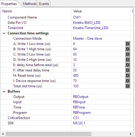
OneWire Component Properties
The Maxim DS18B20 1-Wire temperature sensor has received a major face lifting and command line support:
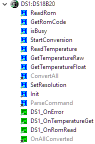
Maxim DS18B20
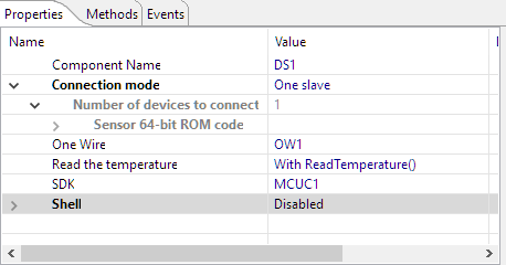
Maxim DS18B20 Properties
RingBuffer
The RingBuffer has a new method Update() to update/change any item in the buffer. The Getn() method is available to get a number of elements:
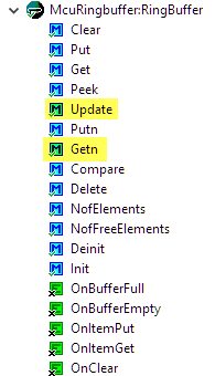
RingBuffer
Summary
The changes are documented on GitHub. The release is available on SourceForge: https://sourceforge.net/projects/mcuoneclipse/files/PEx%20Components/. See “McuOnEclipse Releases on SourceForge” how to install the update. If you are not using Processor Expert: the components are available in normal source form on https://github.com/ErichStyger/McuOnEclipseLibrary.
I hope you find the new release useful.
Happy Updating 🙂
Links
- Release on Sourceforge: https://sourceforge.net/projects/mcuoneclipse/files/PEx%20Components/
- Component installation instructions: McuOnEclipse Releases on SourceForge
- McuOnEclipse Library on GitHub: https://github.com/ErichStyger/McuOnEclipseLibrary

OW1_Init last line
DQ1_ClrVal(Data.TUDeviceDataPtr);
Device_data is wrong ?
Tks
LikeLike
Hi Ricardo,
It should not be wrong, because it is initialized above with
Data.DQDeviceDataPtr = DQ1_Init(NULL);.I have an example using the component on GitHub: https://github.com/ErichStyger/mcuoneclipse/tree/master/Examples/KDS/tinyK20/tinyK20_1Wire
Just a few extra note: because the component uses LDD components, only Kinetis is supported right now (I plan to change this in the future).
The other thing is that the published component does not use templates for the timer and GPIO pin: you have to enabel methods like putting the pin in input mode.
LikeLike
Dear Erich,
Appreciate your great work.
I tried the new lib ,but I got error when generate code :
IDE: codewarrior 10.7
MCU: KEAZ128
Description Resource Path Location Type
Generator: FAILURE: at line 19: Property not found: “szTime” (file: Drivers\Common\OneWireSettings.Inc) ThermalCtrl_ds18b20_test OW1 Processor Expert Problem
Generator: FAILURE: at line 20: Property not found: “szProgram” (file: Drivers\Common\OneWireSettings.Inc) ThermalCtrl_ds18b20_test OW1 Processor Expert Problem
Generator: FAILURE: at line 17: Property not found: “szOutput” (file: Drivers\Common\OneWireSettings.Inc) ThermalCtrl_ds18b20_test OW1 Processor Expert Problem
Generator: FAILURE: at line 18: Property not found: “szInput” (file: Drivers\Common\OneWireSettings.Inc) ThermalCtrl_ds18b20_test OW1 Processor Expert Problem
Generator: FAILURE: at line 13: Property not found: “readTime” (file: Drivers\Common\OneWireSettings.Inc) ThermalCtrl_ds18b20_test OW1 Processor Expert Problem
Generator: FAILURE: at line 14: Property not found: “waitTime” (file: Drivers\Common\OneWireSettings.Inc) ThermalCtrl_ds18b20_test OW1 Processor Expert Problem
LikeLike
I’ll have a look and post an update. Seems the .inc file is somehow out of sync.
LikeLike
Looks like the OneWireSettings.Inc file in the distributed update file still contains old properties 😦
You can fix this on your side:
Open the Drivers\Common\OneWireSettings.Inc and remove the offending lines (or make the file empty).
I’m in the process to replace the BitIO_LDD with a normal BitIO and timer component, so it works with the SDK. Should I post a that new version for you?
I ask because with that new version you would have to configure the timer and pin again.
LikeLike
Thanks for your quick reply. Sure , it is appreciated to get a new version. It is easy to configure the timer and pin .
LikeLike
Dear Eric,
The DS1.c code need revise .
When DS1_CONFIG_MULTIPLE_DEVICES enabled , got the following error.
If DS1_CONFIG_MULTIPLE_DEVICES enabled, should change all things like
Sensor.Rom to Sensor[x].Rom
request for member ‘Temperature’ in something not a structure or union DS1.c /ThermalCtrl_ds18b20_test/Generated_Code line 343 C/C++ Problem
request for member ‘Rom’ in something not a structure or union DS1.c /ThermalCtrl_ds18b20_test/Generated_Code line 467 C/C++ Problem
request for member ‘Rom’ in something not a structure or union DS1.c /ThermalCtrl_ds18b20_test/Generated_Code line 480 C/C++ Problem
request for member ‘Rom’ in something not a structure or union request for member ‘Rom’ in something not a structure or union DS1.c /ThermalCtrl_ds18b20_test/Generated_Code line 474 C/C++ Problem
LikeLike
Thanks, I have to look into this. I only have used it with one sensor (yet), but ordered more to test with.
LikeLike
I have uploaded new DS12B20 and OneWire components on https://sourceforge.net/projects/mcuoneclipse/files/PEx%20Components/.
it is still work in progress!
LikeLike
By the way , do you have a plan to add search rom function into the onewire lib?
LikeLike
Yes, but not sure when I get to that point. First I’ll refactor the OneWire so it uses non-LDD component (is in progress) and two issues you have reported.
Unless you want to contribute an implementation?
LikeLike
Dear Eric,
search rom implementation based on LPC13xx is here : https://community.nxp.com/message/788207
I am porting it to Kea .
LikeLike
I have implemented the search now, and it is available on GitHub: https://github.com/ErichStyger/McuOnEclipse_PEx/commit/dac827b45ed66d1dd6bbf49d908ff47b69c17489
LikeLike
Great job! I will try it when I got time.
LikeLike
Pingback: Using FreeRTOS with newlib and newlib-nano | MCU on Eclipse
I need to interface MK60FX512VLQ12 processor from NXP with AD7194 ADC from ADI. AD7194 is a 24 bit ADC and has on chip SPI registers with 8 bits and 24 bits word length. How should I make use of PE components to communicate with AD7194? To my knowledge PE supports only registers having max 16 bits word length in SPI Slave. How can I give commands with 8 bits and 24 bits with the same SPI Component (SynchroMaster or SPIMaster_LDD) ?
LikeLike
Processor Expert SPI (e.g. SynchroSerial) supports any number of bytes. Use the RecvBlock() or SendBlock() method in the SynchroSerial componnt to send or receive any numbers of bytes.
I hope this helps,
Erich
LikeLike
Thanks Erich.
1) I have set basic width as 8 bits and using SendBlock() function to send 24 bits as a block of 3 bytes. But SCLK is generated for only 2 bytes in SendBlock().
2) Also, RecvBlock() doesn’t generate any SCLK from K60. I believe RecvBlock() should generate the required SCLK for the Slave to send the data.
Any ideas or suggestions.
LikeLike
1) You have to pass the number of bytes you want to send as second parameter to SendBlock(), I think you have probaly a programming error there. Are you sure you pass the correct number of bytes?
2) SPI is a bi-directional shift register operation. You have first to send something to receive something. ReceiveBlock() does not clock anything, you have to use SendBlock() first.
LikeLike
PS: https://mcuoneclipse.com/2012/11/12/getting-help-on-processor-expert-components/
LikeLike
1) It was no programming error. SendBlock() generates SCLK for only max 2 bytes if Slave Select Pin is enabled in SynchroMaster. This was solved by removing Slave Select Pin from SynchroMaster and by separately toggling the CS pin which was added as a BitIO component.By doing so any no. of bytes can be sent. Although I really didn’t understand the issue when Slave Select Pin is added.
2) Thank you for correcting my concept regarding RecvBlock(). Now I am sending dummy SendBlock() after the actual SendBlock() for receiving data from SPI. But still the RecvBlock() returns data value of 0 and there is no activity on the SDO line as seen on the CRO.
Please help.
LikeLike
1) interesting! I never have used Slave Select Pin toggling (this only makes sense if you have one slave on the bus, but if I have one slave, I don’t need that chip select).
2) ReceiveBlock() uses a buffer which has ben filled during the SendBlock() operation, so you won’t see any SCLK activity during ReceiveBlock(), as it only uses the content in RAM of the buffer. What is the buffer size you have specified in the component? Make it large enough so it can hold all bytes (say 32 or 64 is a typical setting).
LikeLike
Hi Erich. Finally solved the problem. It was a hardware issue. Needed to pull-up the SDO line. After that I could capture the data sent on SDO line using a CRO.
The same also reflected in the data returned by RecvBlock().
Once again thank you for the prompt reply and support from your end.
Please do look into the issue of not able to send more than 2 bytes if Slave Select Pin is enabled in SynchroMaster component. That will be a very useful addition for the tool as such. Thank you !!!
LikeLike