
If you are a frequent reader of this blog, then you know: I’m a big fan of Processor Expert components. While there are many Processor Expert components delivered with CodeWarrior, it lacks many components and device drivers beside of the normal on-chip peripherals. But value gets added to an embedded project with all the external devices, sensors and actuators. That’s why I have created many more components which are available on my GitHub site. Readers of this blog have asked several times to create a tutorial on how to create a Processor Expert component. So why not working on that on a long Easter weekend full of cold rain and snow?
So here we go: a tutorial how to create a Processor Expert component for the MMA8451Q accelerometer found on the FRDM-KL25Z board:

MMA8451Q Accelerometer on the FRDM-KL25Z Board
Warning
This tutorial is hard-core, with tips and tricks to work around some issues you might meet. But once you through the traps and pitfalls, creating component can be very addictive. You have been warned :-). Developing Processor Expert component at least in the current stage of the Eclipse based CDE (Component Development Environment) is not the simplest thing in the world. But very rewarding once you master it.
💡 There exists the non-Eclipse ‘classic’ BeanWizard in CodeWarrior for MCU10.2. This BeanWizard is much easier to use in my view, but not available in MCU10.3 any more, and has been replaced by the Eclipse based one I’m showing here. The good thing with the Eclipse based one is that there is a free ‘Community Edition’ license (see below), while the BeanWizard requires a CodeWarrior Professional Edition License. It is possible to use the classic BeanWizard as well within MCU10.3. If there is interest about trying this out, post a comment and I consider writing a post about how to use the BeanWizard in MCU10.3. 🙂 On the other side: every new tool (and especially development method) requires a learning phase, and Freescale is constantly improving the CDE for Processor Expert.
Overview
In this tutorial I’m creating a simple driver for the Freescale MMA8451Q accelerometer. The MMA8451Q is a cool accelerometer with a lot of features, and connected with a I2C bus to the microcontroller. I need that driver for my lecture project, so this is a ‘real’ thing. As such, I’m documenting things as I go, and I plan to frequently update and extend that component. So I plan to post more tutorials.
Processor Expert Component Development Environment (CDE)
Processor Expert is using ‘components’ to generate software and drivers. While CodeWarrior comes with many components, it is possible to create your own components. The components are written in a ‘C-like’ scripting language.
I’m not explaining every concept behind components (see this link as a starting point for other documentation provided by Freescale), as this would be too much as a starter. So here just a few basic concepts and terms:
- Methods: These are like normal C functions. An example would be something like
ReadAccelerometerValue(),orNeg()for a LED: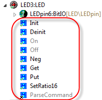
LED Methods
- Events: This are callback which can be called by the component in an asynchronous way. It is a way to notify the application. An example would be
OnFreefallDetected()orOnError().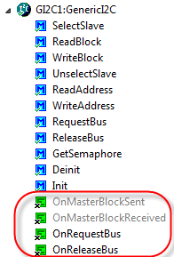
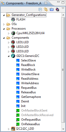
GenericI2C Events
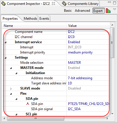
- Properties: these are static settings in the component. Things like an I2C address.

I2C_LDD Properties
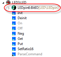
- Inheritance and Interface: It is possible to re-use another component, either ‘incorporating’ it or to interface with it. For example the LED component inherits from the BitIO component to do low-level bit I/O operations:

Inherited Component


The create a component for Processor Expert component, I use the ‘CDE’ (Component Development Environment which is part of CodeWarrior for MCU and the Driver Suite (e.g with IAR). In the past an expensive (Professional) license was required to create Processor Expert components. Recently Freescale has made a ‘Community Edition’ license available which is free of charge for open source/non-commercial components. See this link for details. A time bombed license file is available here on this page.
💡 Future updates of CodeWarrior, Processor Expert and Driver Suite very likely have this community edition license already integrated.
Starting Point
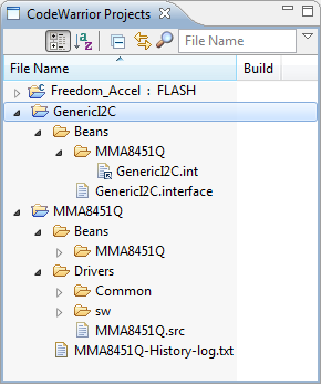
I already wrote a tutorial how to use the MMA8451Q here, but this was not using a dedicated component for the accelerometer. Since then I have updated the project to use my GenericI2C component:
Project with GenericI2C
💡 The reason why I use the GenericI2C component is this: I want to have my software and components working both for devices having LDD (Logical Device Drivers, e.g. for Kinetis) and non-LDD devices (like S08 and ColdFire). The LDD concept in Processor Expert has been very disruptive, and only the recent CodeWarrior for MCU10.3 release has improved the software compatibility. Still, I need an extra software layer for I2C. Painful, but necessary for now. But the advantage is: I can use all my I2C based sensors immediately with my GenericI2C component, independent of the driver architecture Freescale offers me: the power of re-using software 🙂
Starting Point
It is a good idea to have something working as normal C files as starting point. This makes transformation of the driver into a component much easier. For this tutorial, I have the MMA8451Q working with this simple driver interface:
/* * MMA8451.h * * Created on: Mar 30, 2013 * Author: Erich Styger */ #ifndef MMA8451_H_ #define MMA8451_H_ #include "PE_Types.h" uint8_t MMA8451_GetRaw8XYZ(uint8_t xyz[3]); uint8_t MMA8451_Deinit(void); uint8_t MMA8451_Init(void); #endif /* MMA8451_H_ */The driver implementation looks like this:
/* * MMA8451.c * * Created on: Mar 30, 2013 * Author: Erich Styger */ #include "MMA8451.h" #include "GI2C1.h" /* External 3-axis accelerometer control register addresses */ #define MMA8451_CTRL_REG_1 0x2A /* MMA8451 3-axis accelerometer control register bit masks */ #define MMA8451_ACTIVE_BIT_MASK 0x01 #define MMA8451_F_READ_BIT_MASK 0x02 /* External 3-axis accelerometer data register addresses */ #define MMA8451_OUT_X_MSB 0x01 #define MMA8451_OUT_X_LSB 0x02 #define MMA8451_OUT_Y_MSB 0x03 #define MMA8451_OUT_Y_LSB 0x04 #define MMA8451_OUT_Z_MSB 0x05 #define MMA8451_OUT_Z_LSB 0x06 #define MMA8451_I2C_ADDR (0x1D) /* SA0=1 */ //#define MMA8451_I2C_ADDR (0x1C) /* SA0=0 */ uint8_t MMA8451_GetRaw8XYZ(uint8_t xyz[3]) { static const uint8_t addr = MMA8451_OUT_X_MSB; return GI2C1_ReadAddress(MMA8451_I2C_ADDR, (uint8_t*)&addr, sizeof(addr), &xyz[0], sizeof(xyz)); } uint8_t MMA8451_Deinit(void) { return ERR_OK; /* nothing to do */ } uint8_t MMA8451_Init(void) { static const uint8_t addr = MMA8451_CTRL_REG_1; static const uint8_t data = MMA8451_F_READ_BIT_MASK|MMA8451_ACTIVE_BIT_MASK; /* F_READ: Fast read mode, data format limited to single byte (auto increment counter will skip LSB) * ACTIVE: Full scale selection */ return GI2C1_WriteAddress(MMA8451_I2C_ADDR, (uint8_t*)&addr, sizeof(addr), (uint8_t*)&data, sizeof(data)); }And I’m using it like this:
/* * Application.c * * Created on: Mar 30, 2013 * Author: Erich Styger */ #include "Application.h" #include "MMA8451.h" #include "LED1.h" #include "LED2.h" #include "LED3.h" void APP_Run(void) { uint8_t res=ERR_OK; uint8_t xyz[3]; LED1_On(); LED2_On(); LED3_On(); res = MMA8451_Init(); while (res==ERR_OK) { res = MMA8451_GetRaw8XYZ(&xyz[0]); LED1_Put(xyz[0]>50); LED2_Put(xyz[1]>50); LED3_Put(xyz[2]>50); } LED1_Off(); LED2_Off(); LED3_Off(); }I’m going now to create a Processor Expert driver for it.
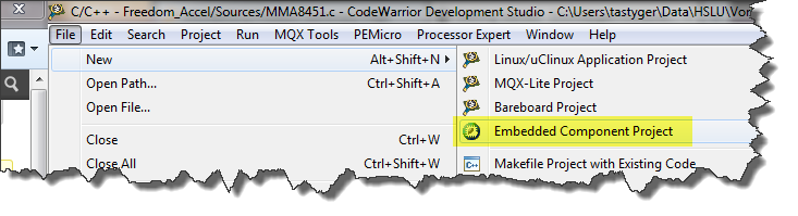
Creating an Embedded Component Project
To create a new component, I select the menu File > New > Embedded Component Project:
New Embedded Component Project
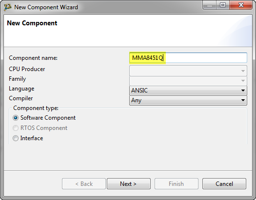
In the wizard, I give a name for my component:
Name for New Component
💡 Choosing a good name is important. It is a good idea not to select a name which is not already used, as Processor Expert cannot handle different components with same name. I have found this out the hard way when I created my LED component, not knowing that Freescale has a LED component for the DSC microcontroller family. Additionally, the component name will used as Eclipse project folder name in workspace. As it is not possible to have multiple projects with the same name in the workspace, better to select a component name not producing a conflict. Alternatively a dedicated Eclipse workspace for components can be used. And it will not be easy to change the name of the component afterwards.
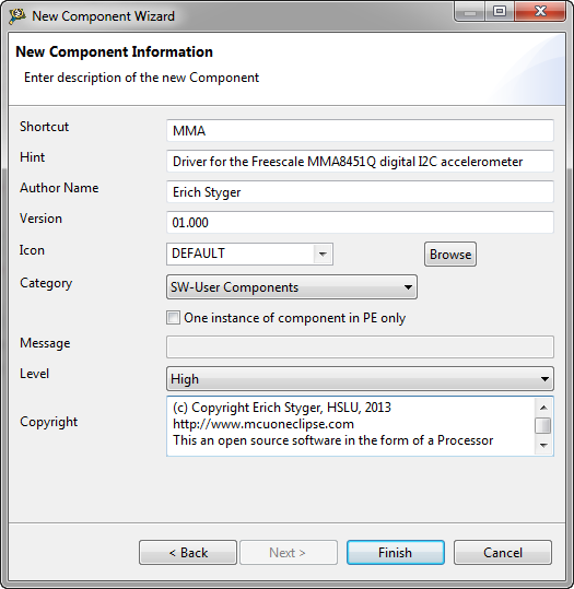
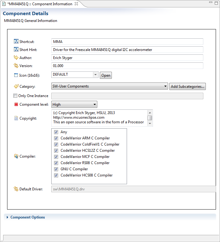
Pressing next, and I can enter the information for my component:
New Component Information
I do not need to worry much about the entries, as I can change them later on.
💡 the ‘Shortcut’ will be used in my driver as prefix (plus a number) for the methods and events (e.g.
MMA1_OnError()). With this in mind, it is a good idea to keep it to 3 to 4 characters only.Pressing Finish will create the component project in my workspace:
MMA8451Q Component Created
Component Details
The Component Details editor view shows (most of) the information we just have entered:
Component Details Editor View
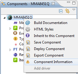
That view can be re-opened any time with the Component Information context menu on the component itself:
Component Information Context Menu
💡 To edit an item in the Component, simply use either the context menu or double-click on it to open an editor view.
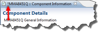
A ‘*’ mark in the view shows me that the settings have not been saved yet:
Dirty Editor Marker
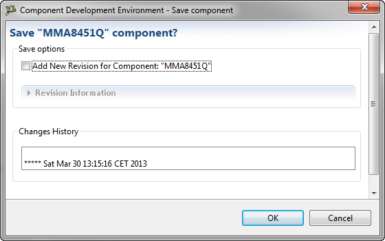
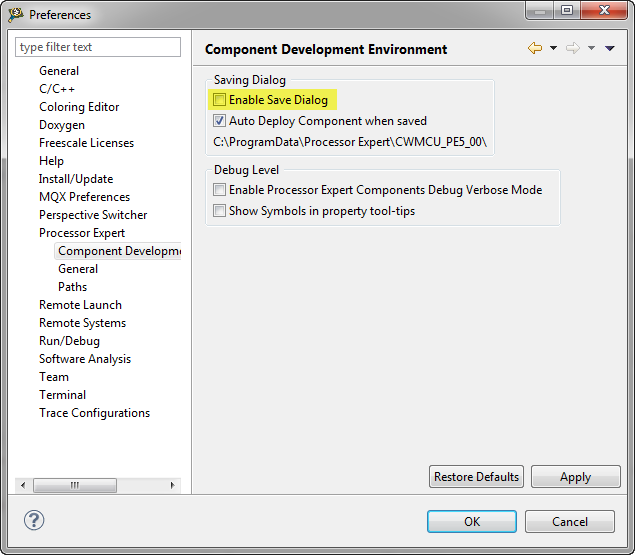
CTRL+S (for Save) will store the settings. A dialog will pop up:
Save Dialog
💡 This dialog will be very annoying. Luckily it is possible to switch it off. For this I use the menu Window > Preferences > Processor Expert > Component Development and switch it off:
Disabled Save Dialog
Adding Properties
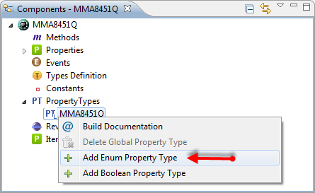
The MMA8451Q can have two different I2C addresses: either 0x1D or 0x1C.
I want the user to select the address from a drop-down (enumeration list), so first I add a new Enumeration Property Type with the context menu:
Adding Enum Property Type
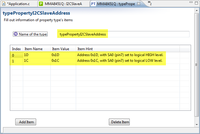
Then I specify a name and add (‘Add Item’ button) two different enumeration values. The ‘Item Name’ is what the user will see in the drop-down list:
Defined Enumeration Property Enumeration
💡 I explicitly set the ‘Item Value’ to a value I can use later on. That Item Value is technically a string type, but I can use it ‘as is’. You will see later on how this works.
Save it with CTRL-S.
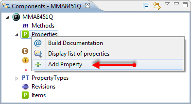
Next step is to add the property itself with the context menu:
Adding Property
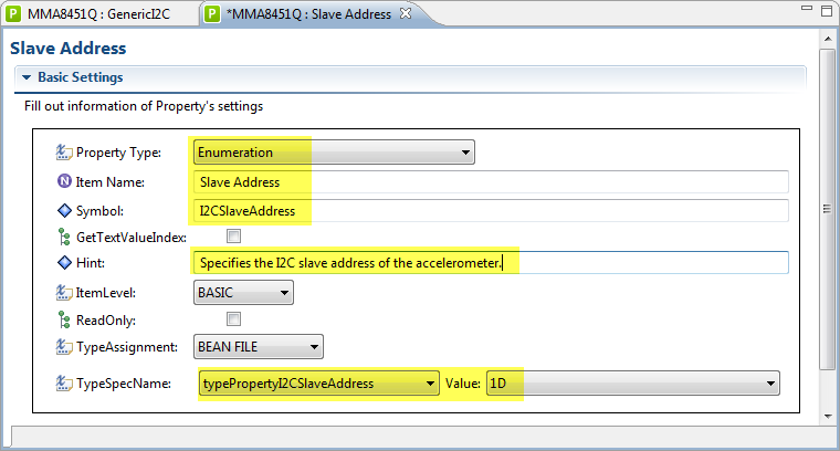
For the property, I specify that this is an Enumeration, give it a name (this will be visible to the user). The Symbol name is what I will use in my code. As type I specify the enumeration type I just have defined with its initial Value:
Slave Address Property Settings
Save the settings with CTRL-S.
Inherited Component (Interface)
For my accelerometer, I need to talk to it using the I2C protocol. So I need to interface (or inherit) to such an I2C component. In my case this is the GenericI2C component.
There are two ways how I can inherit or share a base component:
- Inherited component (interface): With this, the component I inherit from will be part of my component. A typical case is the LED example from above where the BitIO component is ‘inside’ the LED component, and every access to the BitIO component goes through the LED component.
- Link to component: here I have an interface to the component with a ‘link’. That inherited component is not ‘inside’ my component, but ‘outside’. This means that other components can inherit from it too.
❗ Dealing with interfaces is probably the most difficult part in CDE. Messing things up means you can really screw up your component. Better you explore things slowly, and do regular backups of your component.
I want to interface (or inherit from) the GenericI2C component. But as there might be other components which need to inherit from it, I use the ‘Link to component‘ way.
❗ The way how Processor Expert is using ‘inheritance’ and the terms around this topic are ‘non-standard’, and this can be very confusing, as the inheritance schemes and details are different from other object-oriented terminology.
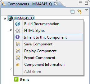
In order to ‘inherit’ (well, ‘link to’), I need first to define the ‘interface‘. The interface is nothing more than basically defining the method and event interface to what I want to interface to. For this I select ‘Inherit to this Component’:
Inherit to this Component
❗ The term ‘Inherit to this Component’ can be very misleading (again): what it does here is defining an interface.
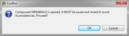
This triggers this dialog:
Confirmation dialog
❓ Not sure why this dialog even shows up if my component settings are all saved?
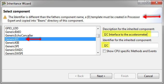
Then, in the following dialog I select the GenericI2C component:
Inheritance Wizard
❗ Note the warning in the dialog header. This is because I inherit from GenericI2C, but I use a different identifier (I2C) for my interface. The reason is that if I’m not doing this, CDE will create a global interface for me, which I definitely do not want and need. I need a local interface to a global component. This was supported out of the box in the old classic BeanWizard, but the Eclipse based only supports this with the changes I’m doing in this step and below. I want to have my interface named ‘I2C’ (to have it generic), and I want to have the GenericI2C assigned as template. More on this in the next steps.
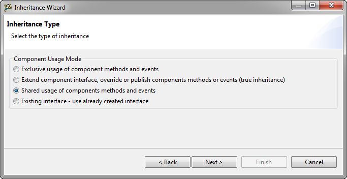
Pressing Next will get me to a dialog where I can specify the type of inheritance. As I want to share the GenericI2C component, I select ‘shared usage’:
Shared usage
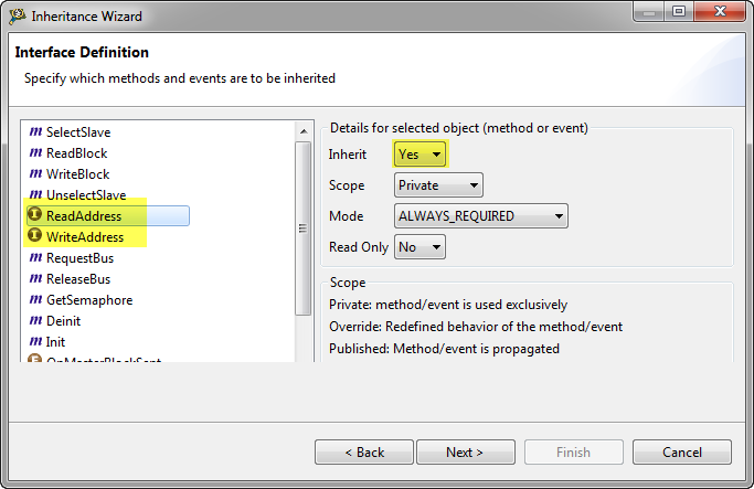
Next, I can specify which methods and events I want to use: I select ‘Inherit: Yes’ for
ReadAddress()andWriteAddress(), as I want them to be used from my component:Interface definition
💡 I don’t need to worry too much about the interface definition in this dialog. I can change things at a later stage. With this, I even can not inherit anything here, and change my mind later on.
Pressing next gets me to the next dialog:
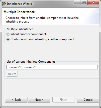
Multiple Inheritance
This introduces another concept: multiple Inheritance. Similar to the concepts above, this is probably not the same what you would typically understand under ‘multiple inheritance’ in object-oriented languages. What it means here is that you can interface to different components. For simplicity, I keep the settings (as I can change things later) and press Next.
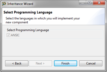
In the next dialog, I cannot change anything, so time now to press ‘Finish’:
Select programming language
I will notice that the interface has been added to my workspace as a folder:
Interface added to Workspace
❗ The fact that the interface has been added as a folder into my workspace has the consequence that I cannot have multiple interfaces with the same name inside my workspace, which is a problem, as I want to have interfaces like MMA8451Q\GenericI2C and e.g. RTC3232\GenericI2C. Because it would be the same interface name (even for different components), this is not supported with this CDE approach. As a workaround I use different workspaces.
Property for the Interface
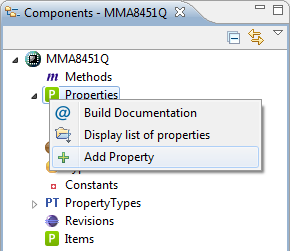
I want to be able to select my newly created interface as a property in my component. For this, I could a new property if CDE has not already added one:
Adding new Property for Link to Component
But CDE should already added the property if you followed the above steps. If not, use the ‘Add Property’ context menu as shown in the previous screenshot.
Added Property for Inherited Component
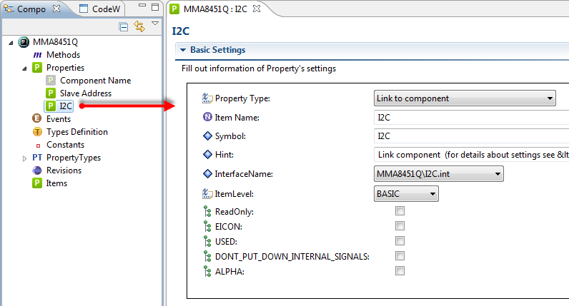
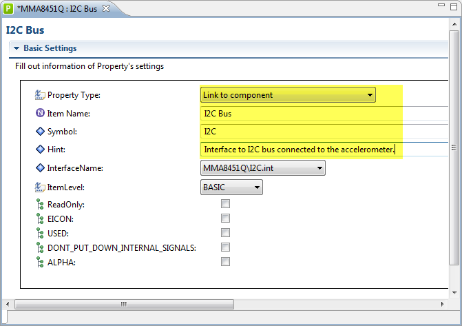
Next, I’m verifying the settings and extend the description:
Link to Component Setting
The ‘Item Name’ is what will be shown in the user interface, while the ‘Symbol’ is what I will use in my code. As InterfaceName I select the just created interface which shows up under my Component name (MMA8451Q\I2C.int).
Assigning Template to Inherited Interface
Remember the above step where I decided to use ‘I2C’ instead of ‘GenericI2C’? This means, that I have an interface named ‘I2C’, and now need to assign a ‘Template’ to it so Processor Expert knows which components are ‘compatible’ with it.
💡 The fact that I need to register a template to an inherited interface is problematic. It means that without assigning a template of a ‘yet-to-built’ component, I can not interface with it. At least this is what happened to me: If I do not register a template, I cannot use it as interface. For example if I would implement another ‘GenericI2C_Other’ component, even if the interface matches, without having it assigned as template to the interface I cannot use it. And I need to be careful not to use a local template (within the component), because then I cannot select a global component for my interface. The best way is always to choose an interface name which is not likely to conflict with a component name.
So I’m going to register the GenericI2C component as template to the interface. For this I open the interface file (*.int) inside the component structure and search for :
Interface file open in text editor
Then replace the I2C template with the GenericI2C one:
<Registration> <Template>GenericI2C</Template> </Registration>Later, if you want to allow more components to interface with your component, simply add extra Template lines within the block.
💡 It is possible to register a template to an interface with the CDE GUI too: for this I would need to import the interface, and then register the template. But this will create an interface project folder in my workspace, and for whatever reason somehow my interfaces and templates got screwed up. So at least to me just using a text editor was faster and worked always :-).
Adding Methods
Now I’m going to the following methods to my driver:


Init(): Initialize the driver, allocates any needed memory data structure.Deinit(): Counterpart toInit().GetRaw8XYZ(): returns the raw 8bit accelerometer values.
To add a new method, I use the context menu ‘Add Method’:
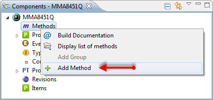
Adding Method
First, I configure the Init() method:
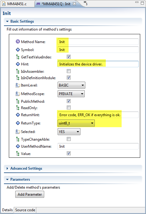
Init Method
Using the ‘Source code’ tab I switch to the implementation of this method:
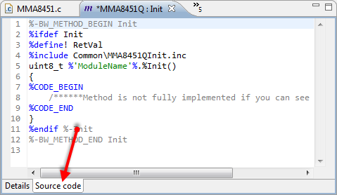
Source Code of Init Method
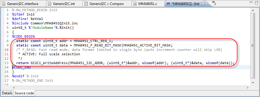
Next, I copy my existing driver code into the block after %CODE_BEGIN:
static const uint8_t addr = MMA8451_CTRL_REG_1; static const uint8_t data = MMA8451_F_READ_BIT_MASK|MMA8451_ACTIVE_BIT_MASK; /* F_READ: Fast read mode, data format limited to single byte (auto increment counter will skip LSB) * ACTIVE: Full scale selection */ return GI2C1_WriteAddress(MMA8451_I2C_ADDR, (uint8_t*)&amp;addr, sizeof(addr), (uint8_t*)&amp;data, sizeof(data));Copied Driver Init Code
❗ Only make changes between %CODE_BEGIN and %CODE_END, unless you know exactly what you are doing!
Wait, something is not ok. I’m have spent so much time above for my I2C interface, so I better use it ;-). To use an inherited interface method, the following syntax is used:
%@InterfaceName@'ModuleName'%.MethodNameWith this, I’m changing my return statement to
return %@I2C@'ModuleName'%.WriteAddress(MMA8451_I2C_ADDR, (uint8_t*)&amp;addr, sizeof(addr), (uint8_t*)&amp;data, sizeof(data));Next, I need to add the MMA8451Q register #defines.
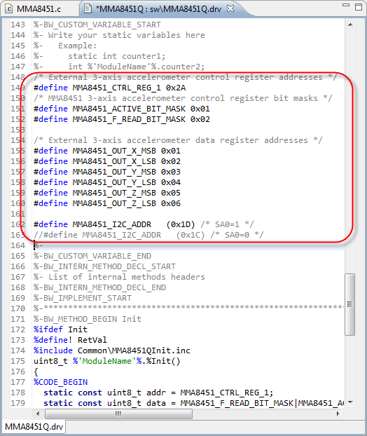
For this I open the driver and search for BW_CUSTOM_VARIABLE_START:
Driver with custom variables start area
That’s just the beginning of my driver module, so a good place for my defines I want to keep inside my implementation module:
/* External 3-axis accelerometer control register addresses */ #define MMA8451_CTRL_REG_1 0x2A /* MMA8451 3-axis accelerometer control register bit masks */ #define MMA8451_ACTIVE_BIT_MASK 0x01 #define MMA8451_F_READ_BIT_MASK 0x02 /* External 3-axis accelerometer data register addresses */ #define MMA8451_OUT_X_MSB 0x01 #define MMA8451_OUT_X_LSB 0x02 #define MMA8451_OUT_Y_MSB 0x03 #define MMA8451_OUT_Y_LSB 0x04 #define MMA8451_OUT_Z_MSB 0x05 #define MMA8451_OUT_Z_LSB 0x06 #define MMA8451_I2C_ADDR&nbsp;&nbsp; (0x1D) /* SA0=1 */ //#define MMA8451_I2C_ADDR&nbsp;&nbsp; (0x1C) /* SA0=0 */I’m adding my defines there:
defines added
But what about the I2C address defines? I have now a property in the component for this. So I can reference to the value of the property using
%SymbolNameI have used the symbol name ‘I2CSlaveAddress’, so I can change it to
#define MMA8451_I2C_ADDR&nbsp;&nbsp; (%I2CSlaveAddress) /* I2C slave device address as set in the properties */With this knowledge, it is easy to add the
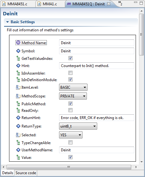
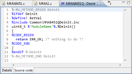
Deinit()method properties and code:Deinit Method Properties
Deinit() driver source code
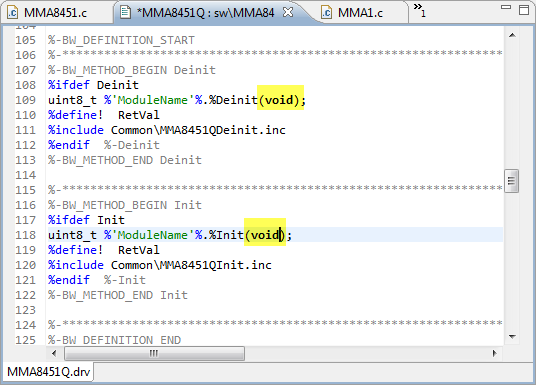
If you are a good C/C++ programmer, you probably have spotted a bug in CDE for the above driver code: there is no ‘void’ in the method parameter list :-(.
In C, the following
void foo();is not the same as
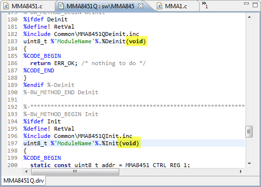
void foo(void);The first declaration does not declare any parameters (so it could be zero, or one parameter, or any number of parameter), while the second version with ‘void’ defines the interface that there are no parameter. While the ‘classic’ BeanWizard properly uses (void) for a method without parameters, this is wrong in CDE for MCU10.3. To fix this, I edit the .drv sources and add the void to it, both for the declaration and the implementation:
Fixed Driver Code Declaration
Fixed Driver Code Definition
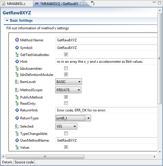
Next to add the
GetRaw8XYZ()method:GetRaw8XYZ Method Properties
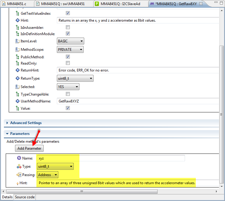
This method requires a parameter:
Added Parameter
❓ This translates into ‘uint8_t *xyz’ which is not exactly the same as ‘uint8_t xyz[3]’. The classic BeanWizard has the ability to specify parameters of any kind, while the Eclipse based CDE misses that capability. While it would be possible to define a custom type, I’m not going down that road here.
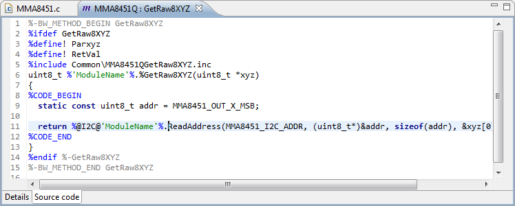
GetRaw8XYZ() Method Source Code
static const uint8_t addr = MMA8451_OUT_X_MSB; return inherited.I2C.ReadAddress(MMA8451_I2C_ADDR, (uint8_t*)&amp;addr, sizeof(addr), &amp;xyz[0], 3);Changing Icon
Our shiny component only will look professional, if it has a nice icon :-). It is possible to create a custom icon for it, as long it is a 16×16 pixel bitmap file.
❗ Note: the pixel at (0,0) defines the transparent background color. See this post.
I can create a new icon (16×16 pixels). The easiest way is to copy an existing one (e.g. from my GitHub repository) and modify it with Paint or any other Windows Bitmap program.
I recommend to place the component icon bitmap file into the Beans folder of the component, with the same name as the component (MMA8451Q.bmp):
MMA8451Q Component Icon
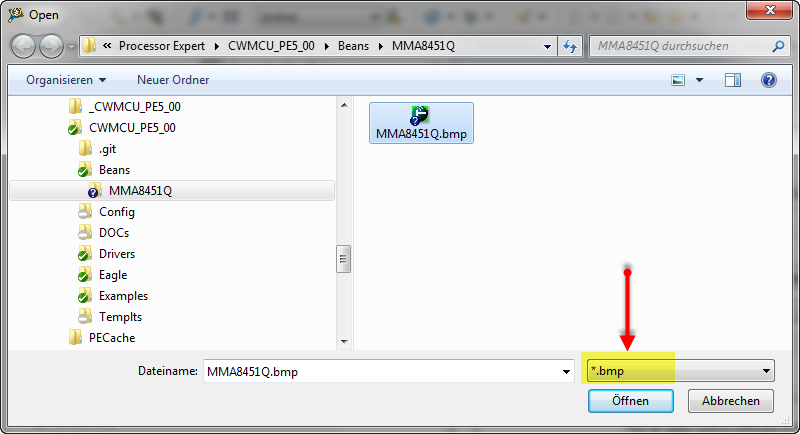
Then I use the Open button:
Open for a new Icon
Then browse to the location where the bitmap file is and then open that file:
❗ Note: select *.bmp as filter.
MMA8451Q Bitmap File
Now I have a cool icon for my component:
Updated Icon for Component
❗ There is bug in the current CDE (at least in CodeWarrior for MCU10.3): the user icon is not shown in the Components Library view. It still shows the default user one. The reason seems to be that the bitmap conversion/settings are not stored properly. I still have the ‘classic’ BeanWizard, and with this one I’m able to convert and set the bitmap correctly.
Trying it out
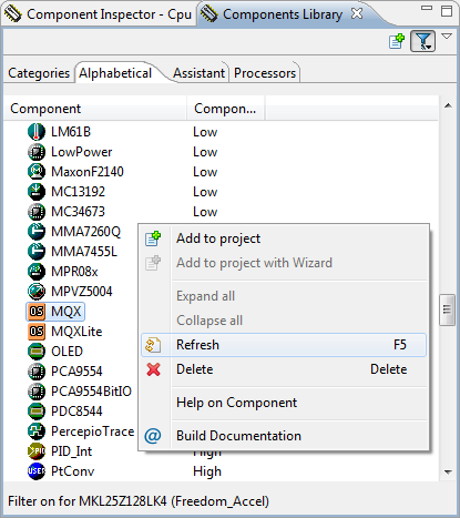
So far my Components Library view is not showing my new component: I need first to refresh the list:
Refresh Components
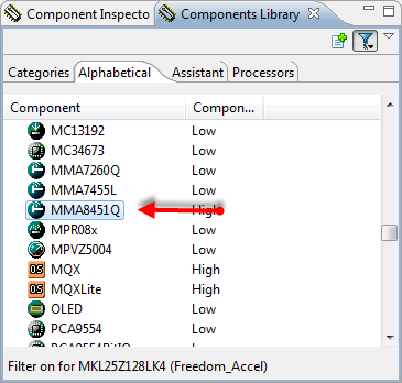
With this, my new component shows up:
MMA8451Q in Component Library
💡 In case the component shows up with the default/blue icon, then this is probably the Icon problem I have described above. Converting/setting the Icon with the classic BeanWizard works.
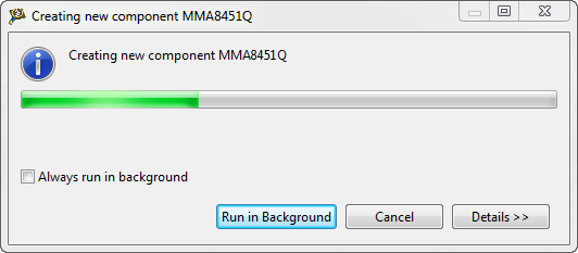
I double-click on the component to add it to my project:
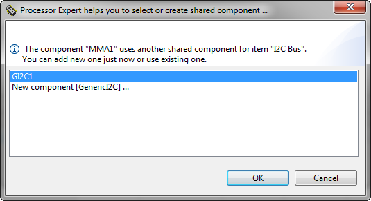
Creating new Component
Then it will ask me either to create a new shared component for I2C, or to use an existing one. As I already have a GenericI2C component in my project, I can select the existing one:
Selecting Shared Component
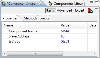
In the component Inspector, I see now the default I2C slave address plus the I2C Bus interface selected:
Component Inspector
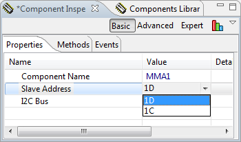
For the Slave Address, I can select one of the enumeration values I have defined earlier:
Drop Down with Predefined Enumeration Values
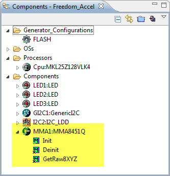
With the new component added to the project, it shows up with the three methods as defined:
New Component with Methods
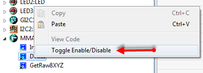
There is one problem: sometimes the methods are marked with an ‘x’. This means they are disabled. I use the context menu to enable them:
Toggle to Enable the Method
❗ I believe this is a bug in CDE in MCU10.3, as I feel I have my settings correct, and it works as expected with the classic BeanWizard.
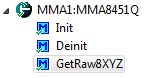
With this, all my methods are enabled:
All Methods enabled
Generated Code
Time to inspect the generated code:
/** ################################################################### ** THIS COMPONENT MODULE IS GENERATED BY THE TOOL. DO NOT MODIFY IT. ** Filename : MMA1.c ** CDE edition : Standard ** Project : ProcessorExpert ** Processor : MKL25Z128VLK4 ** Component : MMA8451Q ** Version : Component 01.003, Driver 01.00, CPU db: 3.00.000 ** Compiler : GNU C Compiler ** Date/Time : 2013-03-31, 20:24, # CodeGen: 18 ** Abstract : ** ** Settings : ** Contents : ** Init - ** Deinit - ** GetRaw8XYZ - ** ** License : Open Source (LGPL) ** Copyright : (c) Copyright Erich Styger, 2013, all rights reserved. ** http://www.mcuoneclipse.com ** This an open source software in the form of a Processor Expert Embedded Component. ** This is a free software and is opened for education, research and commercial developments under license policy of following terms: ** * This is a free software and there is NO WARRANTY. ** * No restriction on use. You can use, modify and redistribute it for personal, non-profit or commercial product UNDER YOUR RESPONSIBILITY. ** * Redistributions of source code must retain the above copyright notice. ** ###################################################################*/ /* MODULE MMA1. */ #include "MMA1.h" /* External 3-axis accelerometer control register addresses */ #define MMA8451_CTRL_REG_1 0x2A /* MMA8451 3-axis accelerometer control register bit masks */ #define MMA8451_ACTIVE_BIT_MASK 0x01 #define MMA8451_F_READ_BIT_MASK 0x02 /* External 3-axis accelerometer data register addresses */ #define MMA8451_OUT_X_MSB 0x01 #define MMA8451_OUT_X_LSB 0x02 #define MMA8451_OUT_Y_MSB 0x03 #define MMA8451_OUT_Y_LSB 0x04 #define MMA8451_OUT_Z_MSB 0x05 #define MMA8451_OUT_Z_LSB 0x06 #define MMA8451_I2C_ADDR (0x1D) /* I2C slave device address as set in the properties */ /* ** =================================================================== ** Method : MMA1_GetRaw8XYZ (component MMA8451Q) ** ** Description : ** Returns in an array the x, y and z accelerometer as 8bit values. ** Parameters : ** NAME - DESCRIPTION ** uint8_t xyz - Pointer to an array of three unsigned 8bit ** values which are used to return the accelerometer ** values. ** Returns : ** uint8_t - ** =================================================================== */ uint8_t MMA1_GetRaw8XYZ(uint8_t *xyz) { static const uint8_t addr = MMA8451_OUT_X_MSB; return GI2C1_ReadAddress(MMA8451_I2C_ADDR, (uint8_t*)&amp;addr, sizeof(addr), &amp;xyz[0], sizeof(xyz)); } /* ** =================================================================== ** Method : MMA1_Deinit (component MMA8451Q) ** ** Description : ** Counterpart to Init() method. ** Parameters : ** NAME - DESCRIPTION ** Returns : ** uint8_t - ** =================================================================== */ uint8_t MMA1_Deinit(void) { return ERR_OK; /* nothing to do */ } /* ** =================================================================== ** Method : MMA1_Init (component MMA8451Q) ** ** Description : ** Initializes the device driver ** Parameters : ** NAME - DESCRIPTION ** Returns : ** uint8_t - ** =================================================================== */ uint8_t MMA1_Init(void) { static const uint8_t addr = MMA8451_CTRL_REG_1; static const uint8_t data = MMA8451_F_READ_BIT_MASK|MMA8451_ACTIVE_BIT_MASK; /* F_READ: Fast read mode, data format limited to single byte (auto increment counter will skip LSB) * ACTIVE: Full scale selection */ return GI2C1_WriteAddress(MMA8451_I2C_ADDR, (uint8_t*)&amp;addr, sizeof(addr), (uint8_t*)&amp;data, sizeof(data)); } /* END MMA1. */ /* ** ################################################################### ** ** This file was created by Processor Expert 10.0 [05.03] ** for the Freescale Kinetis series of microcontrollers. ** ** ################################################################### */The code looks fine so far.
❓ You might notice that the return ‘hints’ have not been added to the comments. Not sure why CDE does not handle this properly, as I have specified the hints text in the method properties?
I can now change my Application.c to use my new driver generated by the component:
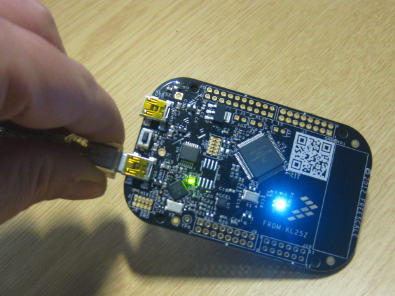
/* * Application.c * * Created on: Mar 30, 2013 * Author: Erich Styger */ #include "Application.h" #if 0 #include "MMA8451.h" #else #include "MMA1.h" #endif #include "LED1.h" #include "LED2.h" #include "LED3.h" void APP_Run(void) { uint8_t res=ERR_OK; uint8_t xyz[3]; LED1_On(); LED2_On(); LED3_On(); #if 0 res = MMA8451_Init(); #else res = MMA1_Init(); #endif while (res==ERR_OK) { #if 0 res = MMA8451_GetRaw8XYZ(&amp;xyz[0]); #else res = MMA1_GetRaw8XYZ(&amp;xyz[0]); #endif LED1_Put(xyz[0]&gt;50); LED2_Put(xyz[1]&gt;50); LED3_Put(xyz[2]&gt;50); } LED1_Off(); LED2_Off(); LED3_Off(); }Build, download and run. And it works 🙂
Application running with new Component Code
Summary
If you are still reading this: Congratulations! You are a Component Warrior and you made it up to here :-). Seriously, things look very complicated at the beginning, and CDE development requires a learning curve, similar to learning a new language and tools. But as you maybe imagine with the components I have developed, it very well pays off. And with the outlook that things likely get easier and simpler in the future, the future is bright for Processor Expert Component development. 🙂
Sources and further reading
The CodeWarrior project used in this tutorial is available here, and the MMA8451Q component is here. A ‘Getting Started’ on CDE can be found here. Additionally have a look at the Freescale CDE Home Page.
Happy Componentizing 🙂


Hello Erich,
When you create a new component, the wizard tool, in component type, shows an item named RTOS component, but it is always disabled. Do know about it?
LikeLike
Hi Juan,
this option is to create an RTOS component, similar to what I did with FreeRTOS. The ability to create an RTOS component is not included in the free-of-charge community license for CDE.
LikeLike
Hey Erich, nice article! Definitely ‘hard-core’ but very digestible nevertheless! I don’t know if you have any back-end web development experience, but a lot of this resonates with me in terms of how server side scripting / templating languages work – except in this case we’re generating C instead of HTML. Pretty neat, thanks.
LikeLike
Hello Erich, I use the CodeWarrior 10.3 and there were a few recent updates. Things are a little different from this latest update.
For example:
When generating the interface is not named ‘I2C.int’ but ‘GenericI2C.int’ and I have to manually rename it so that everything works properly.
About this latest update there appeared new macros in the Processor Expert View.
LikeLike
Hi Alex, I tried to stick with 10.3 base as I think this is what most users have. I did not notice that ‘new macros’ thing. Where have you seen this?
LikeLike
Hi Alex, which update have you installed? Which version shows up in the about box of CodeWarrior? b130515?
LikeLike
Sorry for the delay, I forgot to turn on notifications for this post. :s
Here is a picture of what I mean:
LikeLike
Oh, now I see. The PDD’s have been added to Processor Expert with the latest update. To my understanding these are kind of low level macros in order to access low level functionality with Processor Expert. I have not found out how to make this work. It seems I need to include a header file or something. I see if I can find out.
LikeLike
Hi, I still using the codewarrior version 6.3, and I will like to see how you create a component with this version, thanks
LikeLike
Hi braulio,
do you have a Professional CodeWarrior license? If so, you can launch it with the menu Processor Expert > Component Wizard (or BeanWizard). The concepts are the same, only the UI is different.
LikeLike
Erich,
That was a great post. I attempted to create a component for the HC-SR04 (ultrasonic range finder), but had some issues when I got to the part where I was creating the events. I am not sure how to tie them back to the events from the timer unit. Could you please help me with this (or update this and or the HC-SR04 tutorial post)?
Thanks
LikeLike
Hello Erich, I have no experience with github but I want to to collaborate with the creation of components. I’ve created a component and I would like to know what is the procedure to upload it to the repository and the requirements it should have.
LikeLike
First: thanks very much for your offer to collaborate! The typical way with Git is that you fork the repository, do your modification and then do a pull request. See https://help.github.com/articles/using-pull-requests. What have you created? If it is something simple and a one-off thing, then one way is that you send it to me, and I’ll integrate and publish it.
LikeLike
I created a PID that works with float variables and with which you can specify the type of output variable. I could not put the icon I did for it, by the reason you mentioned above. Give an email where I can send it to you, so you can check it and give me some suggestions.
LikeLike
Hi Carlos,
you find my contact email at the bottom of the About page of this blog.
LikeLike
Pingback: Extended Driver for the MMA8451Q Accelerometer | MCU on Eclipse
Loving the information on this internet website , you have done outstanding job on the posts .
LikeLike
Pingback: How to use MCUonEclipse GitHub without Git | MCU on Eclipse
Pingback: Using the FRDM-KL25Z as a USB Mouse Device | MCU on Eclipse
Pingback: Processor Expert in Eclipse Generating code for L-series microcontrollers >> Karibe
Hey Erich,
Have you thought about adding support for the DSP interrupts into this component?
Vic
LikeLike
Hi Victor,
you mean to support the interrupt line of the accelerometer? Yes, I thought about it, but as I did not need it, I have not implemented it.
Erich
LikeLike
Hi Erich, could you share some bean project to understand how to create it? I can´t open any bean you that created I don´t know why. I tried to create one but return error when using it.
LikeLike
Hi Luciano,
have you seen my components shared on GitHub?
You can import them and then you have plenty of examples.
LikeLike
Yes, I already had imported all but I´d like to edit them to learn how to create new beans. Is it possible to open your embedded component project?
LikeLike
Yes, you can import them in e.g. in CodeWarrior CDE: use the menu File > Import > Component Development Environment > Import Component/Interface.
LikeLike
Now I understand it, thank you for this tip! great job! I love MCUonEclipse and Processor Expert and I will learn more about it.
LikeLike
cool! Let us know your results 🙂
LikeLike
Pingback: DIY: Changing Processor Expert Components | MCU on Eclipse
Just an FYI, there is a link typo for your GitHub acct in the posting in the following section:
…actuators. That’s why I have created many more components which are available on my GitHub site. Readers….
LikeLike
many thanks! It is fixed now 🙂
LikeLike
Great work!! , do you have a one wire componen?
Regards
LikeLike
As I do not have/use any one-wire component, I have not developed a driver for it. So I hope that anyone who uses it would contribute a driver as component?
LikeLike
Hi, I have this error:
“Either LDD or nonLDD interface needs to be defined” GI2C1 Processor Expert Problem
I can not fix it!
do you know how can i fix it?
thanks so much!!
LikeLike
In the GI2C1 component (use the component inspector), there you have to enable either ‘non-LDD I2C’ or ‘LDD I2C’ and configure it. If you are using Kinetis, then you probably want to use the ‘LDD I2C’ option.
You can download one of my projects from GitHub to see how it is used?
LikeLike
Thanks so much,, I would like to know:
how can I put a pin into the high impedance mode?
Regards
LikeLike
Use it as input pin with internal pull-ups enabled?
LikeLike
thanks so much, again!! I have finally created a new component “one wire bus”, but how can I edit it?
LikeLike
Hi Jose,
great! You might have a look at the documentation available on http://www.freescale.com/webapp/sps/site/prod_summary.jsp?code=PE_CDE
LikeLike
thanks, I have a doubt, why do you need to create a
“static const uint8_t addr” ?
In your Tutorial: Accelerating the KL25Z Freedom Board, you only create a #define MMA8451_I2C_ADDR.
LikeLike
Because GI2C1_ReadAddress() needs an address of a variable.
LikeLike
the % operator in codewarrior is it available?
LikeLike
I have a new component “one wire bus”, inside of a method , I have put this: d=a%8; ,but when I have generated the processor expert code in library onewire.c appears d=a;
LikeLike
I can fix it! I put d=a%%8; thanks so much!!
LikeLike
Yes, you found it: %% ==> %
LikeLike
Hi Erich! thank you very much! how about a tutorial for an SPI accelerometer, isn’t easy as I2C, I already tried with your tutorial for the w5100 but it’s diferent… what do you think?
LikeLike
Hi Diego,
I do not have an SPI based accelerometer, so that does not make much sense for me. Just curious: why do you want (need) an SPI interface to it? I2C so much easier and flexible. SPI only would be better if you need to transmit a lot of data in a very small time, which typically is not the use case for an accelerometer.
LikeLike
Hi Erich, thanks for yet another great blog / tutorial. Your blog has been critical to my ability to learn about these Freescale processors, which I am very new to. I made it through this awesome tutorial and I believe I was able to understand the concepts, but at the very end my new component wouldn’t generate code. This was due to a missing configuration in PE. In the GI2C1 component that gets referenced, I have to select non-LDD I2C or LDD I2C. If I pick non-LDD I2C, there are three options: 1) New component [GenericSWI2C], 2) New component [InternalI2C], and 3) New component [SW_I2C]. If I click LDD I2C (which I assume I need for Kinetis), then I only have one option, New component [I2C_LDD]. Can you provide insight into what those four options mean, and the differences between the non-LDD selections?
LikeLike
The LDD components are Logical Device Driver components (for Kinetis and ColdFire+), which came after the non-LDD ones (which exsists e.g. for ColdFire, S08, S12X and DSC).
The difference is the methods and functions (API) used. I discussed aspects of that in https://mcuoneclipse.com/2012/07/26/there-is-a-time-and-date-for-both-worlds/
LikeLike
Hello Erich,
I would like to improve one of your components, and I understand on how creating new components work. My problem is probably something very silly and simple to solve, but I cannot find the right way to do it: I do not know how to import one of your components from GitHub to Codewarrior 10.6, so I can modify it and create a new version.
I have downloaded the whole github PE repository in a zip file. Could you provide a step-by-step guide to import onw single component to CW in a way that I can modify it using the CDE?
Thanks
Antonio
LikeLike
Hi Antonio,
many thanks for your offer. You can import a component using File > Import > Component Development Environment > Import Component/Interface. However, I have put a warning here: I’m currently *not* using the Eclispe based component development (CDE) environment: I still use the ‘classic’ BeanWizard which was part of CodeWarrior for MCU10.x/classic CodeWarrior. It is a standalone editor/environment, unfortunately not free (I have a professional Edition of CodeWarrior 10.2 which included the license for that BeanWizard). So you can edit/change the components with the new Eclispe based CDE, but the files will be very much different than the ones of the BeanWizard. I’m still using the old BeanWizard because this one is much, much easier and faster to use, and has less issues. So be free to use the Eclipse based CDE wizard, but if the changes are not easy to integrate, I might not be able to merge the change back to the files on SourceForge. 😦
LikeLike
Thanks Erich,
Anyway I found out that it is not necessary to do the changes I wanted to. I am using the 24AAEEPROM component with a 24C16 device, and the options for selecting a device in the component properties do not include the “16” device. I wanted to add the 24C16 device in the component, but I found out that I can configure the component for using the 24C08 device, and it works perfectly.
LikeLike
Hmm, not sure about this. You probably only will be able to use the first 1 kByte, as the 08 device is 1 KByte only.
I will try if I can add the 24C16 device support ‘blindly’ based on the data sheet, and you could try it out?
LikeLike
I have made (untested!) changes to support 24AA16 devices here: https://github.com/ErichStyger/McuOnEclipse_PEx/commit/4c6bd7f763bfe6b4336c276337a73e3ed33e5fa9
Let me know if you can take it from there/test it. 🙂
LikeLike
Pingback: Processor Expert Component Repositories | MCU on Eclipse
excelente Gracias Amigo
LikeLike
Pingback: Overview: Processor Expert | MCU on Eclipse
Hi Erich,
if you have some time can you explain your code a little bit.
I did not understand your entire Code.
For example this one:
>>
>> /* External 3-axis accelerometer control register addresses */
>> #define MMA8451_CTRL_REG_1 0x2A
>> /* MMA8451 3-axis accelerometer control register bit masks */
>> #define MMA8451_ACTIVE_BIT_MASK 0x01
>> #define MMA8451_F_READ_BIT_MASK 0x02
>>
>> /* External 3-axis accelerometer data register addresses */
>> #define MMA8451_OUT_X_MSB 0x01
>> #define MMA8451_OUT_X_LSB 0x02
>> #define MMA8451_OUT_Y_MSB 0x03
>> #define MMA8451_OUT_Y_LSB 0x04
>> #define MMA8451_OUT_Z_MSB 0x05
>> #define MMA8451_OUT_Z_LSB 0x06
>>
What exact are you doing here?
I am new at programming with CodeWarrior on MCU.
But i want learn as much and fast i can.
So maybe you can explain me your Code.
Best Regards
Armend
LikeLike
Hi Armend,
these defines are for the individual bits and device addresses. You need to read the accelerometer device data sheet so you can understand what they mean and are doing.
I hope this helps,
Erich
LikeLike
Hi bro!! Thank you very much for all information you’re posting. It has been useful for me. I want to ask you for a favor, I’m going to make a proyect about RFID technology with FRDM KL25Z so i wonder if you have a component (for CodeWarriror) for RFID. I bought a module RFID-RC522 for Arduino but I want to work it with KL25Z 😀
This is my email: abraham9132@hotmail.com
Thanks!!
Greetings from Mexico!
LikeLike
Hi Abraham,
I don’t have that RFID-RC522 module, but I have the PN7120 working, see https://mcuoneclipse.com/2016/10/08/tutorial-rfid-tags-with-the-nxp-nfc-controller-pn7120-and-eclipse/. With Processor Expert you should be able to have this one easily working with the FRDM-KL25Z too.
Greetings from Switzerland to Mexico!
LikeLike
Hi Erich!! 😀
Do you have a couple of examples using SPI and I2C? I will be very useful for my proyect :D. I haven’t found much information about it with FRDM-KL25Z 😦
Thank you very much again!!
LikeLike
There are several examples. E.g. the FatFS projects using SPI for the SD card, or the nRF projects using SPI for the Nordic nRF24L01+. I2C is use for the onboard accelerometer or for an external RTC. Some examples:
https://github.com/ErichStyger/mcuoneclipse/tree/master/Examples/KDS/FRDM-KL25Z/FRDM-KL25Z_NeoShield
https://github.com/ErichStyger/mcuoneclipse/tree/master/Examples/KDS/FRDM-KL25Z/FRDM-KL25Z_RadioHead_nRF24L01
I hope this helps,
Erich
LikeLike
Hi Erich,
Another great tutorial! Thanks. I am wondering if you’ve ever attempted to create a CPU component? If so, how much time did it take?
Thanks again,
-Mike
LikeLike
No, I have not done that. Of course I could create a ‘simple’ CPU module, but to implement all the clocking/etc would require some kind of data base.
LikeLiked by 1 person
That’s what I was afraid of. My intention is to use a Kinetis MKS22 part, and am trying to determine if it is a worthwhile excersise (starting with an MK22) to create a PEx component for the new micro… I think I will not have the time. I was just wondering if perhaps you had done this type of work already.
LikeLike
Hi Erich.
I created my own componentes with CDE.
How Can I create the *.PEupd file with my own components ??
Thank you
LikeLike
Use File > Export > Component Development Environment > Export to Package.
LikeLike
Thank’s !!
LikeLike