
Playing with RFID and NFC is definitely fun :-), and they are everywhere! For a research project I’m exploring different RFID tags and solutions. I several types around for a long time, but never found the time to actually work on it, so last nightI thought I give it a try, and I have it working with GNU ARM and Eclipse, powered by the NXP FRDM-K64F board 🙂

NXP NFC PN7120S with a FRDM-K64F Board
I had the NXP kit (PN7120 NFC Controller SBC Kit, OM5577/PN7120S) available which came with adapter boards for BeagleBone and Raspberry Pi:
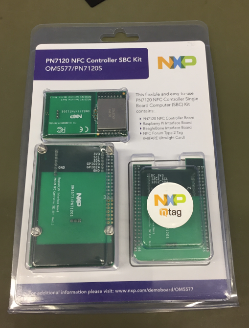
PN7120 NFC Controller SBC Kit OM5577 PN7120S
💡 There is another version of that kit for Arduino (see https://community.nxp.com/docs/DOC-331907), but I was not able to order that one. To use the BeagleBone and Raspberry would be something the future.
There were several articles and tutorials available (see links at the end of this article), but they all did not work out-of-the box for various reasons. So I ended up doing my special tutorial. With the benefit that I learned a lot about how to use that board and I was able to fix issues in the NXP application note and demo code :-).
Material
In this tutorial I’m using the following:
- Eclipse with GNU tools (Kinetis Design Studio V3.2.0, but any other IDE or toolchain could be used): See NXP Kinetis Design Studio v3.2.0
- Kinetis SDK V2.0: see Kinetis SDK V2.0
- Processor Expert with McuOnEclipse components (see “McuOnEclipse Releases on SourceForge“)
- NXP FRDM-K64F board: other boards could be used
- NXP PN7120 Controller board (PN7120 NFC Controller SBC Kit)
- RFID tags for testing (there are two RFID tags included in the above kit)
- Wires and cables
The projects and sources are posted on GitHub:
- SDK version: https://github.com/ErichStyger/mcuoneclipse/tree/master/Examples/KDS/FRDM-K64F120M/FRDM-K64F_PN7120_SDK_v2.0
- Processor Expert version: https://github.com/ErichStyger/mcuoneclipse/tree/master/Examples/KDS/FRDM-K64F120M/FRDM-K64F_PN7120_PEx
NXP PN7120
The NXP PN7120 is an integrated IC with an ARM Cortex-M0 which does all RF communication and NFC related protocol:
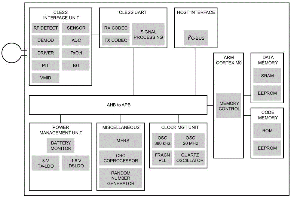
PN7120 block diagram
It simplifies my design as the ARM Cortex-M0 on the PN7120 does all the low level RF stuff, while I can talk to the M0 from another microcontroller over I²C. NXP delivers the library to talk to the PN7120 in full source code as ‘NfcLibrary’. This is what I’m going to use in my application.
Hardware Connections
I²C is used as communication interface to the NFC controller board . The board has the following pins available on each side:
- 3.3V
- I2C_SCL
- I2C_SDA
- IRQ
- VEN
- GND
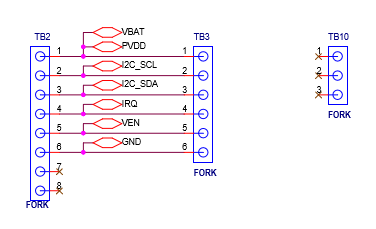
OM5577 schematics
So all what I need is power (3.3V and GND), an I²C connection (SCL and SDA), an interrupt input pin (IRQ) and a GPIO output pin (VEN). The pins are available on both sides of the module:
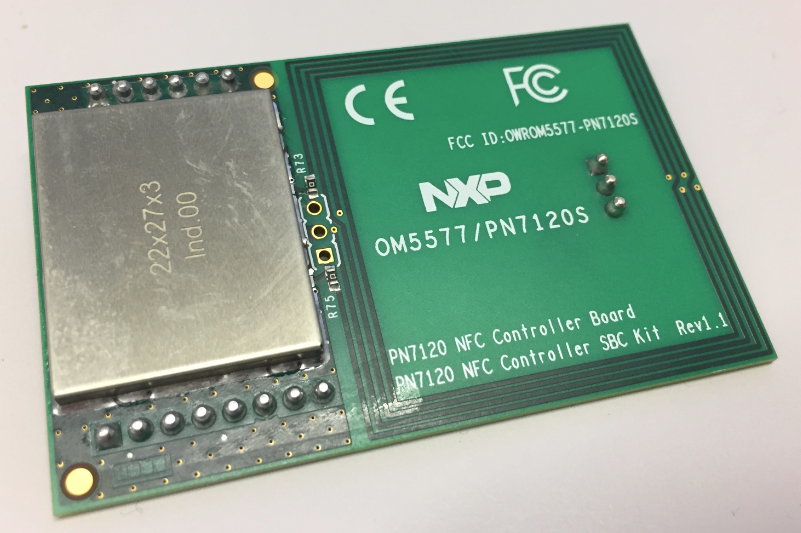
NFC Controller Board Top Side
I’m using a header which I put into the side socket as a connector so I don’t need to solder anything:
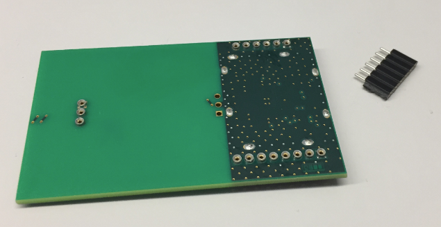
NFC Module Bottom Side
The image below shows my wiring to the FRDM-K64F. I’m using the following pins:
- 3.3V ==> 3.3V
- SCL ==> PTE24 (I2C0)
- SDA ==> PTE23 (I2C0)
- IRQ ==> PTC4
- VEN ==> PTC3
- GND ==> GND
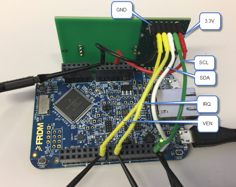
NFC Controller Wiring
💡 Note that I’m using an RevA/Sch-RevC FRDM-K64F board. Newer boards have SDA/SCL swapped!
Software
I have downloaded a zip file from http://cache.nxp.com/documents/software/SW3735.zip
NFC Library
It has the NFC Library with two Kinetis SDK projects. But the projects do not compile because they are not standalone and have wrong settings. I gave up trying to fix the issues. Instead, I create a new project from scratch.
Creating New Project
In Kinetis Design Studio V3.2.0, create a new project with File > New > Kinetis SDK V2.0 Project:
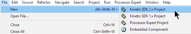
New Kinetis SDK Project
Create a project with all drivers and with FreeRTOS enabled:

SDK Project Creation
NFC Library
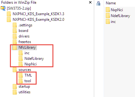
From the SW3735 zip file KDSK2.0 project, copy the following folders into the project:

nfclibrary
- Folder nfcLibrary: the stack communicating with the PN7120
- Folder TML: Transport Mapping Layer, Implements the low level interface, e.g. interrupt handling and I²C communication
- Folder tool: has a delay() function
- File main.c: this runs the demo application
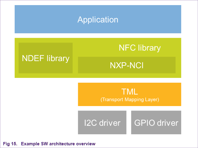
example-software-architecture (Source: http://www.nxp.com/documents/application_note/AN11658.pdf)
I’m placing them into the project so it builds the same directory structure. The file main.c gets replaced with the version from the zip file:
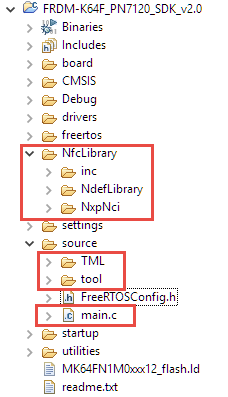
NFC Files in New Project
Include Paths
Because I have added folders with header files, I need to tell the compiler where to find them. I add the following paths to the compiler include search paths of the project properties:
../source/TML
../source/tool
../NfcLibrary/inc
../NfcLibrary/NdefLibrary/inc
../NfcLibrary/NxpNci/inc
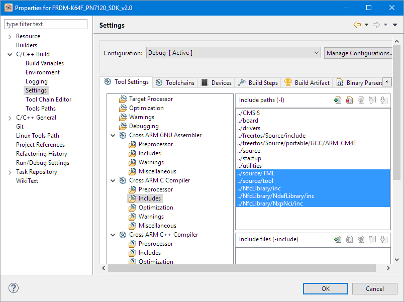
Extended Include Paths
Preprocessor Defines
The source files are using several #defines, so I add the following ones to the project settings:
RW_SUPPORT
P2P_SUPPORT
CARDEMU_SUPPORT
The following defines are supported (see https://community.nxp.com/docs/DOC-331907):
- RW_SUPPORT: With this mode the host can access a remote contactless tag/card via the NFC Controller.
- P2P_SUPPORT: The host MCU can establish a 2-way communication accessing to or sending data to an external Reader/Writer.
- CARDEMU_SUPPORT: The NFC controller host (MCU) can emulate a contactless card which can be accessed by an external Reader/Writer.
- NCI-DEBUG: If defined, all information transferred between the host MCU and the NFC Controller Interface (commands, responses, notifications, data) is echoed to console for debug purposes.
Disabling Interrupts
We are going to use FreeRTOS, and when we start the scheduler, interrupts get enabled. We have to make sure that interrupts are *disabled* until that point. The default startup code however enables interrupts right before jumping to main(). To keep the interrupts disabled, I edit a line in startup/startup_MK64F12.S and comment that line with “cpsie i”:

Not enabling interrupts in startup code
Pins
In board\board.h I add the following defines for the pins used:
/* NXPNCI NFC related declaration */
#define NXPNCI_I2C_INSTANCE         I2C0
#define NXPNCI_I2C_BAUDRATE         (100000)
#define NXPNCI_I2C_ADDR_7BIT         (0x28)
#if 1  /* use PTC4 instead of PTC12, because PTC12 might be on different pins depending on the FRDM-K64F board revision */
  #define NXPNCI_IRQ_PORTIRQn   PORTC_IRQn
  #define NXPNCI_IRQ_GPIO       (GPIOC)
  #define NXPNCI_IRQ_PORT       (PORTC)
  #define NXPNCI_IRQ_PIN        (4U)
#else /* original example uses PTC12 */
  #define NXPNCI_IRQ_PORTIRQn   PORTC_IRQn
  #define NXPNCI_IRQ_GPIO                (GPIOC)
  #define NXPNCI_IRQ_PORT                (PORTC)
  #define NXPNCI_IRQ_PIN                (12U)
#endif
#define NXPNCI_VEN_GPIO                (GPIOC)
#define NXPNCI_VEN_PORT                (PORTC)
#define NXPNCI_VEN_PIN                (3U)
The original demo was using PTC12 which is mapped to different pins on the FRDM-K64F board, depending on the board revision. That’s why I’m using PTC4 instead.
In board\pinmux.c add the following to the includes:
#include "board.h"
Inside BOARD_InitPins() add
    /* Declare and initialize for pull up configuration */
    port_pin_config_t pinConfig = {0};

#if 0 /* internal pull-up on I2C as workaround: do *not* use this for real! */
    pinConfig.pullSelect = kPORT_PullUp;
#if defined(FSL_FEATURE_PORT_HAS_OPEN_DRAIN) && FSL_FEATURE_PORT_HAS_OPEN_DRAIN
    pinConfig.openDrainEnable = kPORT_OpenDrainEnable;
#endif /* FSL_FEATURE_PORT_HAS_OPEN_DRAIN */
#endif
The original demo code had enabled the internal pull-up resistors for the I²C lines as a workaround, if the bus does not have pull-ups installed. The internal pull-ups are usually weak ones, so does not work in most cases any way, so be careful relying on this. As the FRDM-K64F has pullups on the board for the I2C0 lines, I don’t need that workaround.
To configure the pins, I have added the following code inside BOARD_InitPins():
    /* Initialize I2C0 pins below */
    /* Ungate the port clock */
    CLOCK_EnableClock(kCLOCK_PortE);
    /* I2C0 pull up resistor setting */
    PORT_SetPinConfig(PORTE, 24U, &pinConfig);
    PORT_SetPinConfig(PORTE, 25U, &pinConfig);
    /* I2C0 PIN_MUX Configuration */
    PORT_SetPinMux(PORTE, 24U, kPORT_MuxAlt5);
    PORT_SetPinMux(PORTE, 25U, kPORT_MuxAlt5);

    /* Initialize NXPNCI GPIO pins below */
    /* Ungate the port clock */
    CLOCK_EnableClock(kCLOCK_PortC);
    /* IRQ and VEN PIN_MUX Configuration */
    PORT_SetPinMux(NXPNCI_IRQ_PORT, NXPNCI_IRQ_PIN, kPORT_MuxAsGpio);
    PORT_SetPinMux(NXPNCI_VEN_PORT, NXPNCI_VEN_PIN, kPORT_MuxAsGpio);
    /* IRQ interrupt Configuration */
    NVIC_SetPriority(NXPNCI_IRQ_PORTIRQn, 5);
    EnableIRQ(NXPNCI_IRQ_PORTIRQn);
    PORT_SetPinInterruptConfig(NXPNCI_IRQ_PORT, NXPNCI_IRQ_PIN, kPORT_InterruptRisingEdge);
The above enables the clock gates, muxes the pins for I²C, IRQ and GPIO and configures the interrupt priority.
💡 Have a read of a special series starting with “ARM Cortex-M, Interrupts and FreeRTOS: Part 1” about interrupt priorities and FreeRTOS on ARM Cortex-M.
Running it…
With this, have all files saved, build and debug it.
Open a terminal/console with 115200 baud to the OpenSDA UART port of the board, and you should see something like this:
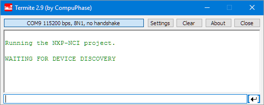
demo-app
Using the sticker tag which was on the PN7120 box:
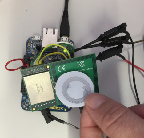
Reading RFID with NXP FRDM-K64F Board
It gives this output:
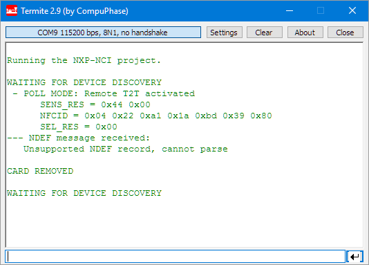
Ntag Message
I do have as well a few 1K Mifare cards from Adafruit, and here I can read and write the cards:

mifare-1k-card
I’m able to read and write RFID cards now :-).
💡 The ability of reading/writing RFID cards depends on the security protocol. Mifare cards use a protocol which has been compromised, see https://en.wikipedia.org/wiki/MIFARE.
Processor Expert
Using the Kinetis SDK with the PN7120 is possible, but many and rather complicated steps are necessary. Using Processor Expert not only makes it easier and simpler, it is portable that way too :-). Plus not all Kinetis devices are supported by the Kinetis SDK.
I have published the Processor Expert project on GitHub here: https://github.com/ErichStyger/mcuoneclipse/tree/master/Examples/KDS/FRDM-K64F120M/FRDM-K64F_PN7120_PEx
The steps are very similar to the SDK project:
- Create a project for the board with Processor Expert enabled
- Add the NfcLibrary, TML and tool folders to the project
- Add the same preprocessor defines as for the SDK project
- Add the same include paths to the compiler settings as for the SDK project
- Add FreeRTOS
- Add Shell component with a communication device (e.g. serial or USB)
- add BitIO (output pin) for VEN
- Add ExtInt for the interrupt line from the module, triggering on raising edge
- Add the GenericI2C component for the I²C communication
With this I have the basic project (I have added thre extra components for the board RGB LED):

processor-expert-project-for-pn7120
Because the original demo is using printf() (outsch, see “Why I don’t like printf()“), in order to keep the original demo code, I have added a wrapper to printf() (see my code on GitHub).
In the TML code I have replaced the interrupt handler and the I²C read/write routines with the Processor Expert driver calls:
void PORTC_IRQHandler(void)
{
  BaseType_t xHigherPriorityTaskWoken = pdFALSE;
  xSemaphoreGiveFromISR(IrqSem, &xHigherPriorityTaskWoken);
}

static Status I2C_WRITE(uint8_t *pBuff, uint16_t buffLen)
{
  uint8_t res;

  GI2C1_SelectSlave(NXPNCI_I2C_ADDR_7BIT);
  res = GI2C1_WriteBlock(pBuff, buffLen, GI2C1_SEND_STOP);
  GI2C1_UnselectSlave();
  if (res==ERR_OK) {
    return SUCCESS;
  }
  return ERROR;
}

static Status I2C_READ(uint8_t *pBuff, uint16_t buffLen)
{
  uint8_t res;

  GI2C1_SelectSlave(NXPNCI_I2C_ADDR_7BIT);
  res = GI2C1_ReadBlock(pBuff, buffLen, GI2C1_SEND_STOP);
  GI2C1_UnselectSlave();
  if (res==ERR_OK) {
    return SUCCESS;
  }
  return ERROR;
}
That’s it! much easier and simpler in my view. All the code for muxing and pin configuration I was able to strip out because Processor Expert takes care of this.
Comparison
Using Processor Expert was not only much faster and simpler. The code and data comparison of the two projects doing the same is interesting (no compiler optimizations turned on).
Kinetis SDK V2.0 version:
arm-none-eabi-size --format=berkeley "FRDM-K64F_PN7120_SDK_v2.0.elf"
   text       data        bss        dec        hex    filename
  65012        340      15652      81004      13c6c    FRDM-K64F_PN7120_SDK_v2.0.elf
Processor Expert version:
arm-none-eabi-size --format=berkeley "FRDM-K64F_PN7120_PEx.elf"
   text       data        bss        dec        hex    filename
  36152        364       9108      45624       b238    FRDM-K64F_PN7120_PEx.elf
The RAM (bss) size needed by the Processor Expert version is much smaller, mostly because the SDK version is using an excessive amount of heap and task stack. But the code (text) for the of the SDK drivers is nearly twice as much as needed by the Processor Expert version!
Summary
I have now the ability to read and write (! 🙂 ) different RFID cards and tags. For example I can read now my SwissPass card or my university badge with this project :-):

Reading SwissPass
While the SDK V2.0 version works fine, it needs nearly the double amount of FLASH and RAM compared using Processor Expert, mostly because the SDK driver code seems to use a lot of layers and the example uses excessive amount of RAM I think mostly because of printf()?
The Kinetis SDK project is available on GitHub: https://github.com/ErichStyger/mcuoneclipse/tree/master/Examples/KDS/FRDM-K64F120M/FRDM-K64F_PN7120_SDK_v2.0
The Processor Expert project is on GitHub here: https://github.com/ErichStyger/mcuoneclipse/tree/master/Examples/KDS/FRDM-K64F120M/FRDM-K64F_PN7120_PEx
Happy RFIDing 🙂
Links
- PN7120 web page: http://www.nxp.com/products/identification-and-security/nfc-and-reader-ics/nfc-controller-solutions/full-nfc-forum-compliant-controller-with-integrated-firmware-and-nci-interface:PN7120A0EV?lang_cd=en
- PN7120 Kit: http://www.nxp.com/products/identification-and-security/nfc-and-reader-ics/nfc-controller-solutions/development-kits-for-pn7120-plugn-play-nfc-controller:OM5577
- Application note: http://www.nxp.com/documents/application_note/AN11845.pdf
- Example project: cache.nxp.com/documents/software/SW3735.zip
- Article about using PN7120: https://community.nxp.com/docs/DOC-331907
- NXP Kinetis Design Studio: NXP Kinetis Design Studio v3.2.0
- NXP Kinetis SDK: Kinetis SDK V2.0
- Adafruit article about Mifare: https://learn.adafruit.com/adafruit-pn532-rfid-nfc/mifare
- Sources on GitHub: https://github.com/ErichStyger/mcuoneclipse/tree/master/Examples/KDS/FRDM-K64F120M/FRDM-K64F_PN7120_SDK_v2.0

Erich, do you know if it is possible to buy just the PN7120 NFC controller board, without the other interface boards ?
LikeLike
Hi Geoff,
I had exactly the same thought, but did not find the board without the other interface boards. Anyone?
LikeLike
Hi all,
As far as I know, the PN7120 kit only exists in the form of the package shown at the beginning of this article.
LikeLike
Hi Amine,
thanks for the confirmation from your side. To bad, because in my view this very much limits the adoption of this great device in the market, especially in the hobby market. Do you think there is any chance that this might change?
LikeLike
Hello Erich. Thanks for the tutorial, very helpful.
Any idea how do we go from this to being able to transfer files from the dev kit to an android device and vice versa. Would be helpful. I am looking at this in order to be able to extract log files or upgrade software/configuration of the K64.
Thanks in advance.
Ylber
LikeLike
Hello Erich,
I am using another RFID module for lab classes, which uses the IC MFRC522. It is a quite popular module for Arduino users. I tried to port the Arduino library to a KL25 board, but I am having problems communicating with this module. Is there any chance that we have a Processor Expert component for this module soon?
Thanks in advance,
Antonio
LikeLike
I believe I have one of this modules somewhere around. I just must find it, plus the needed time to write the component. So chances are not zero 😉
LikeLike
Hello,
I followed this example step by step but when i debug they give me :
“Running the NXP-NCI project.
Error: cannot connect to NXPNCI device”
I do not know where the error is?
LikeLike
It basically means that it cannot communicate with the device. Most likely your hardware connection and wires is not done correctly. Or you are missing the I2C pull-ups?
LikeLike
hello Erich Styger,
thank you for your quick reply, I checked my hardware connection its correct I use Irq over pta0 pin and I mentioned it on pin_max.c and board.h
but about i2c pull-up I don’t know what your mean and how I can do it, if it’s possible to give me more information please,
best regards
LikeLike
I2C requires pull-ups on clock and data lines, see https://en.wikipedia.org/wiki/I%C2%B2C
LikeLike
Hi Erich, Thanks so much for your guide! I am currently experiencing difficulties with running the example. I am using the PEx example, which i imported, but my program seems to hang once the it calls I2C_MasterSendBlock in the generated GI2C1.c source file. The program waits for the dataTransmittedFlg value to go true, which never happens. I feel as though it is due to the interrupt not detecting sent data.
Are you able to point me towards how I could go about debugging my issue?
LikeLike
Hi Rob,
common reason for this is having the interrupts disabled. Are you using my exact example program or your own? Can you check in the Registers view with the debugger if the PRIMASK bit is set (interrupts disabled)?
I hope this helps.
LikeLike
I have had a look and it seems the interrupts are enabled so that isn’t the issue. Maybe I was not clear regarding the interrupt: looking at the signals the I2C seems to work fine, I see the voltage get pulled to 0 then back to ~3.3V. The VEN signal seems to stay high 3.3V persistantly and my IRQ signal stays at 0V. I am wondering if the VEN signal should stay high? if that is okay I just wonder why my pn7120 is not sending the IRQ signal back.
PS I have imported your exact project in, the only modification is my SCL and SDA are opposite as my board is the newer revision. Other than this all the same, my IRQ is PTC4 and VEN is set to PTC3
LikeLike
VEN should be HIGH to enable the device. It is used to reset the device (pulling it low for about 100 ms or so), otherwise it should stay high.
LikeLike
Edit: I noticed that actually the I2C pulls low and then stays low when the program gets stuck.
LikeLike
The question would be if the microcontroller pulls the line low or the device?
LikeLike
it looks to be the microcontroller, it initiates the write in the “GI2C1_WriteBlock” and gets a return value on the line
“res = I2C_MasterSendBlock(GI2C1_deviceData.handle, data, dataSize, flags==GI2C1_SEND_STOP?LDD_I2C_SEND_STOP:LDD_I2C_NO_SEND_STOP);”
but then it hangs on:
“while(!GI2C1_deviceData.dataTransmittedFlg);”
My conclusion is that, for whatever reason, the device doesn’t set the “dataTransmittedFlg” which is called on the PE_ISR(I2C_Interupt). I am wondering if you could tell me how the I2C_interrupt should be configured because maybe that is my problem?
LikeLike
This means that your interrupts do not fire somehow. Have you checked with a logic analyzer or oscilloscope if something is sent at all on the I2C data/clock lines?
LikeLike