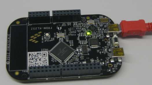
One success factor of the Arduino platform is the broad availability so-called ‘shields’: hardware plugin-modules which extend the capability of platform. Shieldlist.org currently lists 288 different shields available! Clearly, Freescale wants to benefit from that ecosystem with the Freedom FRDM-KL25Z board which features Arduino compatible headers. Time to use the Freedom board with an Arduino shield :-).
Category Archives: Boards
USB CDC and SCI: Side-by-Side with the Freedom Board
In “A Shell for the Freedom KL25Z Board” I have presented an application which implements FreeRTOS, LED’s and a shell using the UART on the KL25Z over OpenSDA. So why not adding native USB CDC to the mix? Using both the USB and CDC with the same shell?
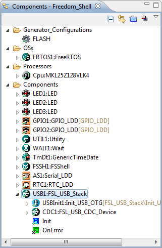
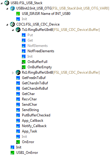
So what I have added is that the shell runs on both the SCI (over OpenSDA) and USB CDC (with the KL25Z). For this, the FSL USB CDC software stack is now part of the project:
Thumbs up with Assembly on ARM Cortex
Sometimes it is necessary to write an interrupt service routine in assembly language. This is the case as well for the ARM Cortex-M0+ which is found in the KL25Z on my Freedom board. But there is something important about the ARM Cortex architecture: Thumb Mode.
Thumb mode the ‘ARM way’ to reduce the code size with a reduced (16bit wide) instruction set. The ARM architecture can implement a ‘mixed’ mode, on a function level. To distinguish between ‘normal’ ARM functions and ‘thumb’ functions, the processor is checking if the LSB (Least Significant Bit) of a function pointer (or function call destination) is set. So a jump address of 0x410 is for a ‘normal’ function, while a function jump to the address 0x411 (even if the function is located at the address 0x410) denotes a ‘thumb’ function.
USB Component Splitted and Updated
Checking the download statistics of my Processor Expert components on http://www.steinerberg.com/EmbeddedComponents/, there is a clear winner: FSL_USB_Stack 🙂
It has been a while I presented that universal USB CDC component in this blog. The component has received a larger re-architecture, I wanted to support more than just USB CDC. For this, the CDC part is now present in a separate sub-component:
Tutorial: Bits and Pins with Kinetis and the FRDM-KL25Z Board
In “Optimizing the Kinetis gcc Startup” I stripped down the fat of my startup code. Now time to add some useful things. And what does a microcontroller like the KL25Z on the Freedom FRDM-KL25Z board have: Pins! And this means I have bits to set and read :-).
Optimizing the Kinetis gcc Startup
The GNU gcc tool chain integration in CodeWarrior/Eclipse MCU10.3 has a nice feature to show the code and data size of my application after linking (see this article how to enable this). So if I create an ’empty’ project with the wizard, get the code and data size without consulting the linker map file:
But wait! 2604 bytes of code for almost doing nothing? That’s not what I want! There are ways to get that puppy much, much slimmer. Down to 284 bytes .
SWD Debugging with the FRDM-KL25Z Board
The OpenSDA on the FRDM-KL25Z board is a cool feature: I do not need any external debugging device to program and debug my board :-). But my KL25Z custom board will not have that OpenSDA on it: first because it would add additional costs, and I do not see a way how I could use it for my board. I better start using a SWD/JTAG debugger for my Freedom board to have everything in place.
What I need to add to the black Freedom board is the SWD header:
How (not) to Secure my Microcontroller
There are several reports in the Freescale forums around having ‘secured’ the Freedom board. But what does ‘securing’ a board mean? And what does it mean if I get that ‘Device is Secure’ dialog?
There are different levels of protection you can find in many embedded microprocessors, and the terms might vary from vendor to vendor:
- Protect
- Secure
- Disable Mass Erase
Using the 8 MHz Crystal on the FRDM-KL25Z Freedom Board
The ARM Cortex-M0+ on the KL25Z Freedom Board (FRDM-KL25Z) runs up to 48 MHz. For this, the 8 MHz crystal on the board is used. A 48 MHz is required for USB communication, to have the needed oversampling on USB data lines. I have shown in my USB CDC post how such a clock is configured, using the white pre-production board. To my surprise, when I tried the same code on the black production boards, it did not work on the production black boards. Even worse: it worked on some, but not on every board :-(.
Unsecuring the KL25Z Freedom Board
In ‘Device is Secure‘ I had a case where this was a false alarm. But recently there has been a report in the Freescale Forum that this can be a real problem with the Freedom KL25Z board I’m using too. I was not able to reproduce this on my end, so a reader of this blog who sent me a binary file to reproduce it.
Well, I was really scared to try that ‘killer’ file on my board, but well, that board is not that expensive, and I have 5 pieces of silicon at hand from a sample order :-). So I took some risk, and programmed that binary using the simple flash programmer. And indeed, when I wanted to debug it again, I got that dialog with my black Freedom board: