When I create a new project for the KL05Z with Processor Expert, then it shows up as 48 pin LQFP package in the project:
However, when I look at my board, it has a KL05Z32 in a LQFP package with 32 pins:
When I create a new project for the KL05Z with Processor Expert, then it shows up as 48 pin LQFP package in the project:
However, when I look at my board, it has a KL05Z32 in a LQFP package with 32 pins:
The first FRDM-KL25Z Freedom Logic Analyzer firmware was missing one important feature: Triggers! But this weekend the firmware has evolved a bit :-).
After working on an ADC example, a DAC one was missing. Julio E. Fajardo is a reader of this blog, and he was so kind to send me an example project for the FRDM-KL25Z. The example is able to produce produce different waveforms with the DAC. The project has two examples which they are enabled/disabled in main()
. One example waveform the sawtooth:
The challenge with small microcontroller like the ARM-Cortex-M0+ is that they have very limited debugging resources. As such, the number of hardware break points is very limited (see this post). For example for the KL25Z on the Freedom board, I only have 2 break points available if I want to do stepping:
I’m using serial communication in different flavors for my project: with the shell, with OpenSDA USB CDC, to use printf(), and with the Bluetooth module. Processor Expert is a big helper, but as for any software, it is not bug free. And there is a problem with Processor Expert in CodeWarrior for MCU10.3 in respect with Baud settings for a serial interface.
In “Using the Reset Button on the Freedom Board as User Button”, I had the problem to find out why a setting did not make it into my generated code. There is the fundamental question: “How does a setting impact my microcontroller register settings?”. There is an answer to that question: The Configuration Registers view:
Processor Expert is a great tool: it lets me configure all the complexities of that ARM Cortex-M0+ core. But today it has fooled me and I lost several hours of my week-end time :-(. I need a user interface like push button for my project. Yes, the FRDM-KL25Z has touch area, but honestly: that kind of stuff never worked out well for me. It is probably just me having it not properly set up. The touch slider is working as in my earlier simple example, but in my other project with more hardware around it, it is working sometimes, sometimes not. Ahrg! I can blame my ignorance, my lack of understand how to configure it properly, or the extra noise by the hardware around it. Result is: I wasted a lot of time, and I give up :-(.
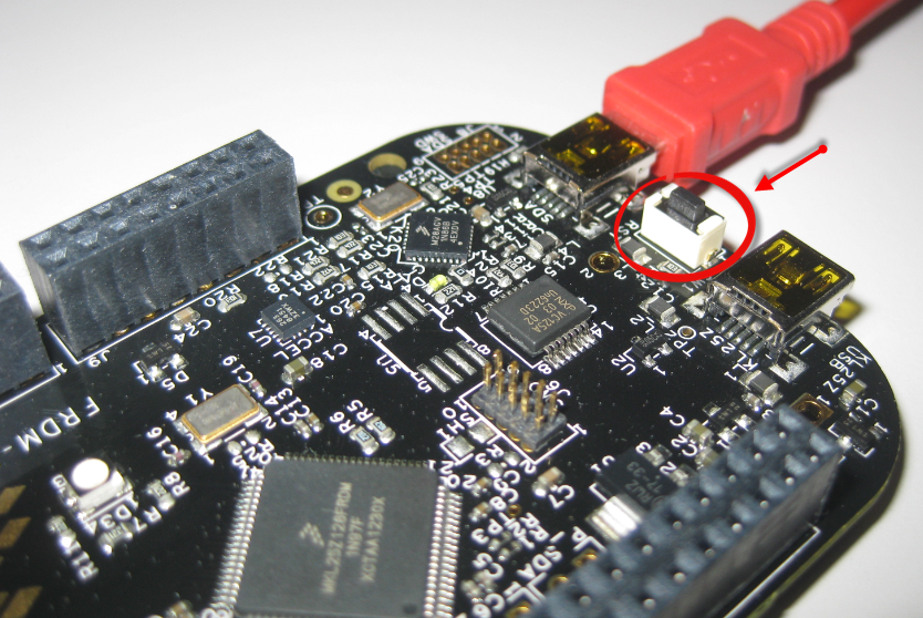
I’m working now on a lecture robot project using my Freedom Board. And for this I need a wireless communication. I already have IEEE802.15.4 (SMAC) working, but I wanted to add Bluetooth as a low-cost option. I have found an inexpensive Bluetooth module which is available for only around $4-8 which we use in another university class project. The module is an AT command module: that means the microcontroller communicates with AT serial commands with the module, and the Bluetooth stack itself runs on the module. In a minimal configuration I only need 3.3V, GND, TX and RX plus a CMD (Command) pin:
One of the great advantage of using an ARM core as on my FRDM-KL25Z board is that I can leverage a lot of things from the community. And one big thing around ARM is CMSIS (Cortex Microcontroller Software Interface Standard). It is an industry wide software library for the ARM Cortex microcontroller. Using the CMSIS libraries and interfaces will make it easier to port applications within the ARM Cortex family.
In ‘A Library with ARM gcc and Eclipse’ I was using the CodeWarrior MCU10.3 beta version to create a library project. At that time I had to do things manually. Now with the final MCU10.3 there is an option in the New Project Wizard which makes things easier:
This will create a library (or better: an archive) with gcc for me. But how to use it from another project?