
I think the most important tool for a firmware engineer is a Logic Analyzer. I always have one on my desk. Working in different locations, sometimes I forget to carry it with me. And for sure I would need it. To buy another one to compensate my laziness? Or maybe there is another solution? And here I stumbled over an article about the Logic Sniffer project recently: it is about an open source logic analyzer hardware and firmware project. What a cool idea! Why not using my FRDM-KL25Z Freedom board as a Logic Analyzer? Heck, that would be awesome 🙂

Logic Analyzer with the KL25Z Freedom Board
After some nights of plumbing and research, I finally have it working. And here is all the information to do the same with your Freedom Board…
💡 While this post is using the Freedom board, it is not limited to that board. Actually the software works with any other microcontroller 🙂
Architecture
LogicSniffer is an OLS-client alternative software client for the Open Bench Logic Sniffer hardware produced by DangerousPrototypes. It is using the original SUMP protocol and an extension of it.

Architecture
The architecture is rather simple: on the Freedom board I have an application running which uses input pins to record the logic signals and stores it into a RAM buffer. The application communicates with the host over COM (Virtual COM, OpenSDA USB CDC in my case) with the SUMP protocol. On the host there is a client implemented in Java running which does all the presentation. Simple as that :-).
CodeWarrior Project
A CodeWarrior for MCU10.3 project is available on GitHub. This project implements a Logic Analyzer probe. It is using the OpenSDA USB CDC port to communicate with the client. I have configured the SCI to communicate with 115200 baud.

Logic Analyzer Components
Once running the probe, the Freedom blinks the red RGB LED:

Flashing Red LED
Connecting to Signals
The Freedom board headers can be used to connect to the external signals. Be aware that GND needs to be connected, and that the FRDM board is 3.3V. So do *not* ❗ connect to higher voltages as this might destroy the board!
Installing OLS Client
I use the Logic Sniffer OLS client, written in Java (cross-platform). I downloaded it from http://www.lxtreme.nl/ols/. Installation is easy: unzip it to a folder on the host machine:

OLS client installed
The client is using configuration files for all the different probes supported. I have prepared a configuration file for the FRDM-KL25Z board. Download the file ols.profile-FRDM-KL25ZLogicLogger.cfg from GitHub and place it inside the plugins folder of the client:
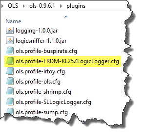
KL25Z profile file inside plugins folder of client
Run the client with the ‘run.bat’ in the client software root folder. This opens a DOS shell and the Java client.
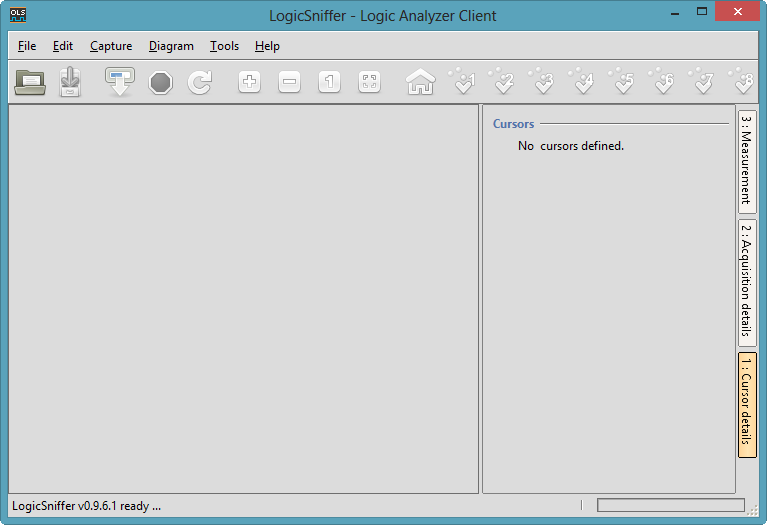
Logic Analyzer Client Main Window
As device, I use the OpenBench LogicSniffer device:
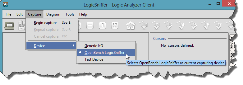
OpenBench LogicSniffer Device Setting
To start capturing, press the ‘Capture’ button:

Start Capturing
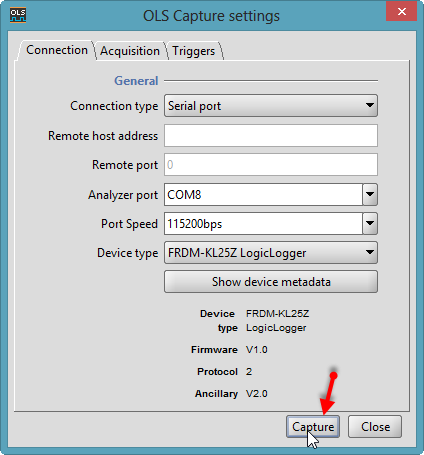
This opens a dialog with the port settings. In the CodeWarrior project I’m using a serial port with 11500 baud:

Port Settings
To verify if communication with the works properly, the ‘Show device metadata’ button is used:
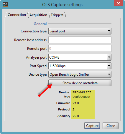
Show Device Metadata
Make sure that the Freedom board is selected as device:

FRDM-KL25Z LogicLogger as Selected Device
❗ It is important to select the correct device, as the configuration file defines the buffer size. If device/configuration does not match, then communication will fail.
Pressing the ‘Capture’ button will start getting the data from the KL25Z:
Capture
The captured data will show up:

Captured Data
Possible Enhancements
The application on the FRDM-KL25Z is a combination of C code and Processor Expert components. I would love to create a Processor Expert component for the firmware (buffer settings, sampling rate, etc) as any of these changes need a manual change of the configuration file. I could generate that configuration file from the Processor Expert component to make things easier. Additionally, I do not support triggers yet (that would be great!). And a more flexible probe pin assignments would be good too (I’m using now 8bit/pins of PTC port).
Summary
I still love my I my Saleae Logic Analyzer: the software and hardware is simply superb! But for hobby projects I have now an open source alternative based on the Freedom board :-). I cannot have the 50 MHz sampling as with the Saleae, but works well for many of my needs.

Freedom KL25Z used as Logic Analyzer on an S08 Board
Happy Analyzing 🙂

Great article Erich. Last week I saw a similar project with ST micro and started investigation how to implement it on freedom board. You have been faster, so thank you for great starting point 🙂
Petr
LikeLike
Thanks :-). I saw a similar thing using the TI Stellaris Launchpad, so I decided that it has to be possible with the Freedom board.
LikeLike
Hi Erich,
this is a great Tool (and a big argument to convince people to invest in a small “professional” Logic Analyzer as soon as they see how useful this little toy can be)!
Expecting this Project to work out of the box, i programmed my FreedomBoard immediately and the Firmware started (LEDR blinking).
The Installation of OLS was also quick done, BUT the FreedomBoard can not be connected to OLS. I tried several free USB Ports, the Debugger finds the OpenSDA device, but the OLS Software does not. My USBDeviceViewer shows the SDA Device on the selected Port.
Any suggestions?
By the way, after importing all FreedomBoard Examples from GitHub, the LED Komponents of several Projects have corrupted BitIO Pin Definitions, and can not be compiled ( i.e. UsbCDC).
(FatFS has a locked GenericI2C component).
LikeLike
Hi Reiner,
OpenSDA (USB CDC) can sometimes tricky. Closing the COM port, unplugging, re-plugging and then re-opening the COM port usually helps. Otherwise the Windows COM/USB port might be stuck.
If you press the ‘Show Device Metadata’ button, it will communicate to the board. Set a breakpoint on line 120 in Logic.c (cmd = GetChar();): it should stop there.
I check the GitHug examples. Are you as well the components from GitHub? The examples are aligned to these components. But I will cross-check on my side.
LikeLike
Hi Erich,
thanks for the speedy reply …..
Sorry, I did not install the new components because i did not find any *.PEupd files 😉 Now i know how to install the Components directly, and guess … they are working as expected! So your Git repository is fine.
But i can not connect to the OLS (even not with the Debugger).
I expect the Problem on my PC side, because there are sometimes Problems with FTDI and SiLabs VCOM drivers on my System. Up to now all other Devices (OpenSDA, other Debugger and Programmer Devices from different Hardwaresuppliers) are working fine. So i think you should not spend more time on this issue until other testers will find similar Problems. I keep you up to date when the Problem is solved.
Happy Coding.
Reiner
LikeLike
Hi Reiner,
ok, good to hear that there is progress. As for the connectivity: I’m using the OpenSDA SCI in my example, but you could change it to any other (real) serial port (if you have one), of course with the correct level shifter. I know that USB CDC sometimes can be a pain….
LikeLike
Hi Erich,
found that the UART used for the Project Example was not UART1 (as is in use for the SDA_CDC USB Port), but UART0. OLS works fine (out of box) if i connect an UART2USB converter like an SiLabs 2102 Breakoutboard to PTA1 and PTA2 of the Freedom Board.
LikeLike
Strange. On my board, the UART0 is connected to the K20 (OpenSDA), and works for me as as USB CDC. With this I can communicate and debug using the same USB cable. Do you have a different board?
LikeLike
Sorry, i identified the labels on the circuit drawing UART1_Rx_TgtMcu not correctly as going TO the K25. I think i better stop for today with fiddling around with USB issues.
Removing all USB Drivers from my PC, and reinstalling only the OpenSDA drivers did not change the situation. Debugging is possible, but no communication with the Example applikation. Using this very small and cheap SiLabs Adapter with fresh installed VCOM drivers at PTA1/PTA2 Pins solved this Problem for today.
http://www.chip45.com/products/iomate-usb1-2.0_cp2102_usb_uart_wandler_modul_board.php
LikeLike
Hi Erich,
as i expected, the Communication to the Freedom OpenSDA CDC Driver was blocked from an Virtual FTDI Driver. This Device was not connected for a long time, but all Drivers ever installed will be loaded to Memory, even if not actually active. But they are not visible inside the Hardwaremanager — until you follow the Microsoft Knowledgebase Item # http://support.microsoft.com/kb/315539/en!
After solving this issue, ALL LOADED Drivers are visible and you will be able to deinstall them comletely. So it seems that not the USB CDC is the pain …..
Happy Coding
LikeLike
Nice. What was the top sampling frequency achieved?
I just got an Open Logic Sniffer board to debug a stupid little bug on my FRDM-KL05 board.
LikeLike
Hi Andrei,
I mostly used it in the few hundreds KHz sampling area, not tweakening things for performance. I have not tried it out to which level it can go. I used it so far to store 8bits per sample. I think limiting the number of bits should give some longer smaplings and as well potentially increase the performance.
LikeLike
Pingback: Freedom Logic Analyzer with Triggers | MCU on Eclipse
Pingback: Freedom Logic Analyzer with DMA | MCU on Eclipse
Pingback: Freedom Logic Analyzer with DMA | minghuasweblog
I have downloaded the source and imported it into codewarrior, but I got error when build it. The error is showed in the picture in this link:
http://www.mediafire.com/?nbfeho6s431xc44
plz help me to fix it.
thank in advance!
LikeLike
Hello,
from your screenshot I see that
a) you have not loaded all the needed components. Please follow the steps described in
b) you need to generate code first. Select the .pe file and use the context menu to generate code.
LikeLike
Follow the steps from your link, I have imported all two parts of *.PEup file from processor expert menu and then do step b). But the errors have not fixed yet. Do I need other steps, like import components which just installed from step a) to my project?
LikeLike
Have you restarted CodeWarrior?
The other thing could be: because you had not the needed components installed, Processor Expert could have assigned the LED_DSC components which are not the ones needed. Can you re-load the original project? Otherwise post a screenshot what you see?
LikeLike
Thank for your enthusiastic reply.
I have it runs on the board now. But have a new problem when connect the board with OLS is that I cannot select device type in OLS capture setting window as your picture show “FRDM-KL25-Logiclogger”, because it isn’t in list of device type.
When I press capture, there is nothing show in screen.
Any suggestions?
LikeLike
You need to place the configuration file. This is described in this part of the post:
“The client is using configuration files for all the different probes supported. I have prepared a configuration file for the FRDM-KL25Z board. Download the file ols.profile-FRDM-KL25ZLogicLogger.cfg from GitHub and place it inside the plugins folder of the client:”
I used this one:
https://github.com/ErichStyger/mcuoneclipse/blob/master/Examples
LikeLike
Yes, I have already read it and done that step. But It not work.
I just built project from codewarrior, and program it to my board, my board run with rbg led red blink. after that I put the .cfg file to plugin folder of OLS, and then run .bat file.
But I cannot capture.
LikeLike
Hmm, strange.
Once you have that .cfg file in the plugin folder of the OLS, it should show up. Are you sure you have rescanned the plugins?
LikeLike
Do I need wire my board exactly as you did?
LikeLike
Yes, this time I even carefully restart my PC, but it still not work. My board have not wire any probe, I just plug usb cable and run it. Is it ok? I think it is.
// ps: because There isn’t reply button from 3rd comment, so I have to post new reply here
LikeLike
You need to connect the board on the OpenSDA USB port. That way the KL25Z microprocessor can have a serial connection to the host using a virtual COM port.
LikeLike
No. All what you need is a serial connection from the FRDM-KL25Z to your host. If OLS correctly recognizes the .cfg file, then it should show up under ‘Device type’. If not, then it has not been recognized.
As for the acutal data capture: it needs a serial (virtual COM) connection to the board. In my screenshots I show COM8. But on your system it is very likely another COM port. Check your device manager which COM port is the correct one.
LikeLike
Thank for your time to help me.
I have it runs now when I download other version of OLS (ols-0.9.6 instead of ols-0.9.7)
Once more time, thanks again
LikeLike
ahh, that would explain it. I’m still on the old version. Not sure why it does not work on the new one.
LikeLike
I compare the ols.profile-ols.cfg with the ols.profile-FRDM-KL25ZLogicLogger.cfg in ols-0.9.7. And found an new Configuration item: device.dividerClockspeed must add into the ols.profile-FRDM-KL25ZLogicLogger.cfg. Then I can see the correct device. Maybe it is the root cause.
LikeLike
Thank you so much! I have not tried it out (yet), but I believe this is really the missing link. Thanks again!
LikeLike
Now is problem with using it.
Here I intend to use my FRDM-KL25 board as an logic analyzer to capture signal from FRDM-Kl46 board. How I can do it? For example, I have program a code which set a pin in from FRDM-KL46 from high to low and toggle that pin each 1second (asume pinA). But when I use a probe which wired J1-CON 2×8 as in the picture and capture from pinA, but there is not any pulse in capture screen.
Plz, guide me how to use it. Thanks!
LikeLike
You need to connect the two boards with GND too. And as shown in the picture, I’m using the pins on PortC.
LikeLike
Hi, I am having trouble with the above Mentioned tutorial. For me everything happens well, untill the capture. I am able to pull up the metadata from FRDM Board, and am able to connect to the board. then when i click start capturing, it hangs, the FRDM board glows the Blue color and nothing happens afterwords.
Kindly Help !
LikeLike
I am having an Issue with the Tutorial,
I am able to connect to the GUI, I am Able to pull the metadata, but once i click the capture button nothing happens. The FRDM board, turns the Blue Light on and stucks :(. I am running Win 8.1 and I have a FRDM Board REVD
LikeLike
What version of OLS are you using? I’m using ols-0.9.6.1, so it could be that using a later version is causing problems?
LikeLike
I tried the sources from GitHub, and maybe I see the problem you are seeing? Have you connected D2 and D0 (see https://mcuoneclipse.com/2013/03/24/freedom-logic-analyzer-with-dma/)?
LikeLike
Hi gsgill112, I have found a problem, and at the end I decided to refactor the DMA support in the project. I just have committed the new sources, including an S19 file, so you can try it out. I will post a blog article on this hopefully tonight. This implementation does not need to bridge the D0 and D2 lines 🙂 Let me know if this works for you.
LikeLike