One of the ‘goodies’ of the FRDM-KL46Z is the Freescale MAG3110 magnetometer. The MAG3110 is a tiny 2×2 mm device:
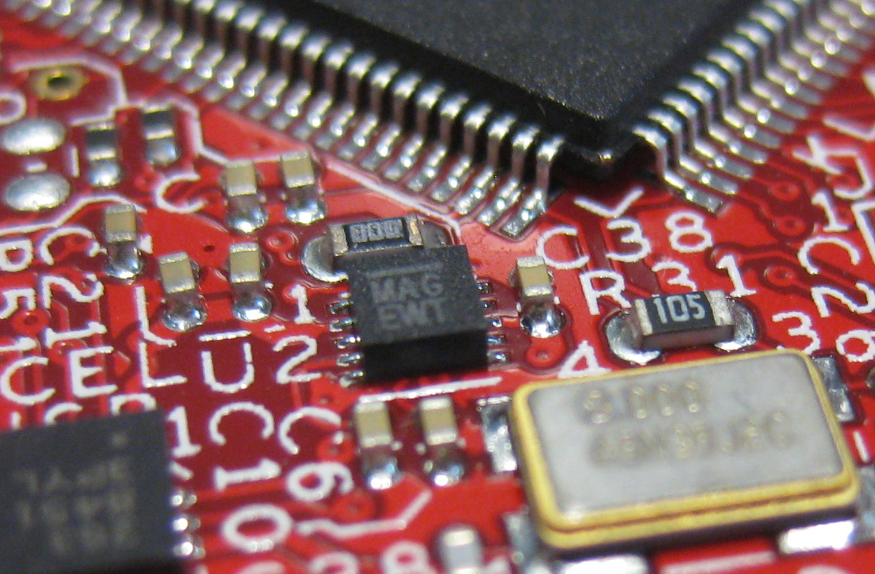
MAG3110 on FRDM-KL46Z
What was missing so far is a Processor Expert component for it. This post is about closing this gap…

One of the ‘goodies’ of the FRDM-KL46Z is the Freescale MAG3110 magnetometer. The MAG3110 is a tiny 2×2 mm device:
MAG3110 on FRDM-KL46Z
What was missing so far is a Processor Expert component for it. This post is about closing this gap…
Not everyone is familiar with Git, and not everyone wants to use it. Although I think using Git or SVN is something every software engineer today needs to master 😉 To make it easier for the ‘non-Gitter’ to use the Processor Expert components, they are available now as *.PEupd files as described here. However, the *.PEupd files are just a snapshot, and not the latest and greatest. So how to use the latest component sources and example projects without Git?

gits in a box
In “Tutorial: Accelerating the KL25Z Freedom Board” I used the MMA8451Q accelerometer on the FRDM-KL25Z board in a very primitive way: I’m reading directly some low-level registers from the device through an I2C low-level component. No calibrating, no special device feature setting, only raw values. Since then, things have been evolved: In “Tutorial: Creating a Processor Expert Component for an Accelerometer” I started to create a driver for this accelerometer, and since then a lot more functionality has been added.

Traced Accelerometer Values to the Shell
If you are a frequent reader of this blog, then you know: I’m a big fan of Processor Expert components. While there are many Processor Expert components delivered with CodeWarrior, it lacks many components and device drivers beside of the normal on-chip peripherals. But value gets added to an embedded project with all the external devices, sensors and actuators. That’s why I have created many more components which are available on my GitHub site. Readers of this blog have asked several times to create a tutorial on how to create a Processor Expert component. So why not working on that on a long Easter weekend full of cold rain and snow?
So here we go: a tutorial how to create a Processor Expert component for the MMA8451Q accelerometer found on the FRDM-KL25Z board:

MMA8451Q Accelerometer on the FRDM-KL25Z Board
The CSI is one of my favorite crime drama television series: not because it reflects the true reality, but because it is fun watching how they always find new ways how to investigate a crime scene with ‘close to reality’ tools. Real CSI is different: you only do a small part of the investigation chain. As for myself, I’m engaged in a research project at the university to develop hardware and software for crime scene investigation :-).
One area of that research project is to retrieve and data from credit card (ATM) skimming devices: these are devices are attached or inserted into credit or debit card machines and ‘skim’ the card information and the PIN code used. With that information, it is possible to clone a credit card for credit card fraud. Such devices are a big problem, and newer devices are very hard to spot. Simply ‘google’ for pictures for “skimming device” and you will get an idea of the diversity and madness of such devices :-(.

Microscopic investigation of skimming device
There was one part missing to complete the software support for my Arduino DataLogger Shield on top of my FRDM-KL25Z Freedom board: support for the Maxim DS1307 RTC (Real Time Clock).
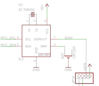
DS1307 on the Adafruit Data Logger Shield (Source: http://www.ladyada.net/make/logshield/design.html)
Things got delayed a bit, as I first needed to get the I2C infrastructure up and running (see this post). But finally, I have things working :-). I proudly present: RTC_Maxim!
I really hate this kind of stuff: I know it should work, but it does not. I’m loosing a lot of time (hours, days, even weeks) to track it down to the root cause. Yes, I create my own bugs. Yes, there are bugs in tools, sources, libraries and components. But what many might not believe: there are bugs in silicon too :-(. If you do not believe, here is one: there is a hardware I2C problem on the KL25Z used on the Freedom board. It worked in one project, but not in another.
❗ The silicon bug described here is present on many Kinetis devices, not only the KL25Z!

Logic Analyzer attached to the FRDM-KL25Z board
So if you are facing a problem where you read 0xFF or wrong values from the I2C bus with the KL25Z, here is probably why (and how to workaround it). The problem showed up with a modified version of the Freedom Accelerometer tutorial….
I’m working with the I2C bus recently a lot. I’m using it in a project to reverse-engineering skimming (credit card fraud) devices. I needed to improve one of my applications for the lecture classes where a MCF52259 is communicating with a TWR-LCD display over I2C. And I want to add RTC (Real-Time-Clock) capabilities to my Arduino Data Logger Shield which requires I2C.
The same time I want to have things working with ARM Cortex-M4 and M0+ devices. And here the challenge started: using the I2C_LDD (Logical Device Driver) Processor Expert components for the ARM Kinetis devices is definitely not simple and easy. I want to use my software compatible for both the ARM cores and say for S08 and ColdFire cores. So what I ended up is to write a ‘generic’ I2C driver on top of the low level Processor Expert components: named GenericI2C.
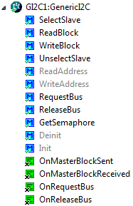
Generic I2C Component
One success factor of the Arduino platform is the broad availability so-called ‘shields’: hardware plugin-modules which extend the capability of platform. Shieldlist.org currently lists 288 different shields available! Clearly, Freescale wants to benefit from that ecosystem with the Freedom FRDM-KL25Z board which features Arduino compatible headers. Time to use the Freedom board with an Arduino shield :-).

Data Logger Shield on Top of Freedom Board
In “Tutorial: Enlightning the Freedom KL25Z Board” I used the RGB LED on the FRDM-KL25Z board. This tutorial extends it to use the MMA8451Q inertial sensor on the board which is connected through I2C to the KL25Z processor:

Freedom Board Block Diagram with MMA8451Q (lower right corner)
The goal is show the accelerometer x, y and z-axis on the RGB LED.
