The CSI is one of my favorite crime drama television series: not because it reflects the true reality, but because it is fun watching how they always find new ways how to investigate a crime scene with ‘close to reality’ tools. Real CSI is different: you only do a small part of the investigation chain. As for myself, I’m engaged in a research project at the university to develop hardware and software for crime scene investigation :-).
One area of that research project is to retrieve and data from credit card (ATM) skimming devices: these are devices are attached or inserted into credit or debit card machines and ‘skim’ the card information and the PIN code used. With that information, it is possible to clone a credit card for credit card fraud. Such devices are a big problem, and newer devices are very hard to spot. Simply ‘google’ for pictures for “skimming device” and you will get an idea of the diversity and madness of such devices :-(.

Microscopic investigation of skimming device
My job in the project is to retrieve the data from the devices. As the newer ones are highly integrated and getting smaller and smaller, usually an inspection with a microscope is a first step.
Depending on the complexity, we can use 3D microscopic scanning machines which are used at the university usually for material inspection.
One real device was inserted *inside* the card slot. Earlier devices where attached in front of the card slot. So these new ones are really hard to detect:
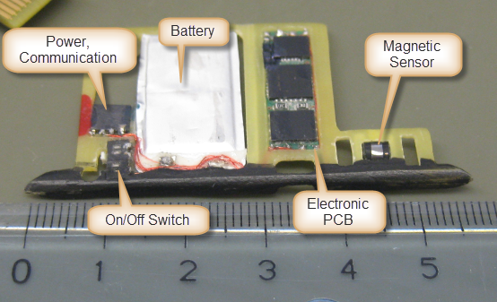
Skimming Device
Usually it is possible to identify the devices used, but not always, as for this case:
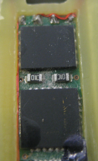
Devices with no labels, slimmed down to the bonding wires!
There devices have the identification removed. Notice the lower device where the surface has been scrubbed up down to the bonding wires! Incredible!
Do you think that removing the identification on the chips has been made to make the work of the investigation forces harder? Not really. They slimed down the PC and the devices on it to fit it into the credit card slot.
Again the microscope is a big help here, and thinking for myself how I would (theoretically!!!) build such a device, and given the components on the PC gives hints what was engineered here:
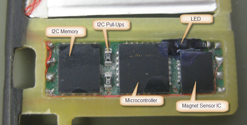
Device Identification
Again, the main goal was to retrieve the data collected to decide which cards have been skimmed. That I2C EEPROM memory is of special interest, and a way to get the data out is to spy it out with another board.
The FRDM-KL25Z is ideal for this: small, easily accessible pins and I have all the needed tools like the Arduino Data Logger Shield which makes attaching to the device easy:

Skimming Device attached to Freedom Board
The problem is now: without knowing what I2C device is used, that might get a difficult task to reverse engineer the protocol. Luckily, most external I2C EEPROM devices use a similar protocol. Still, I need to find out the device address, and probe the device.
In some cases it is possible to watch the device activity on the bus:
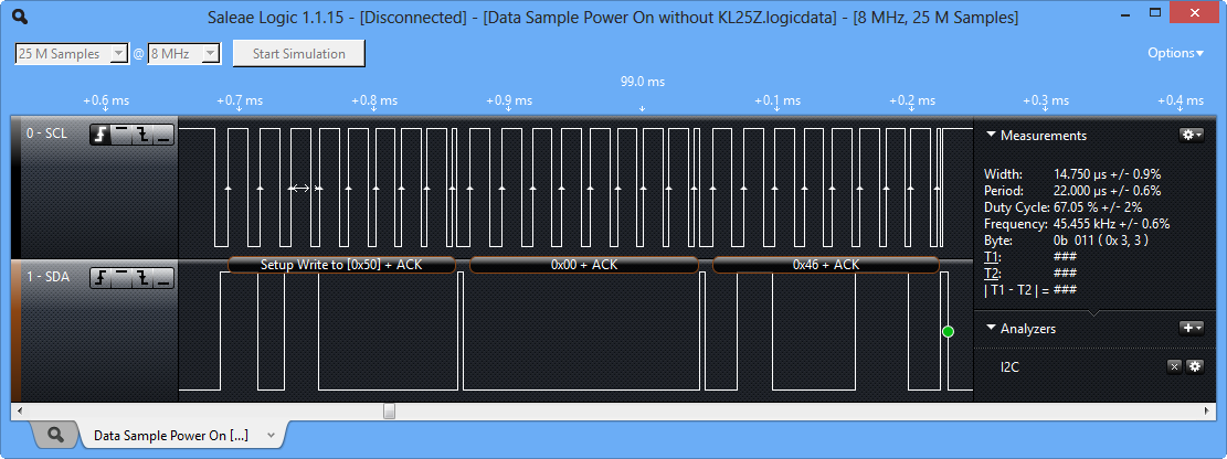
Data Sample on Power On
But this might not be always possible or successful, so probing with software is needed.
I2CSpy Processor Expert Component
To simplify the task, I have developed a shell enabled Processor Expert component which is used to spy out the I2C devices on the bus.
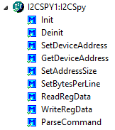
I2CSpy Processor Expert Methods
Using the component properties, it features Shell support:
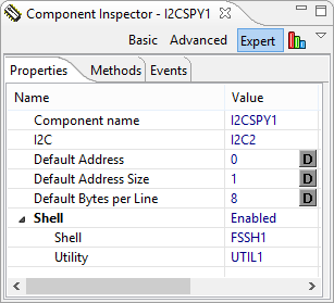
I2CSpy Properties
The component offers a command line interface to probe and inspect the I2C bus:
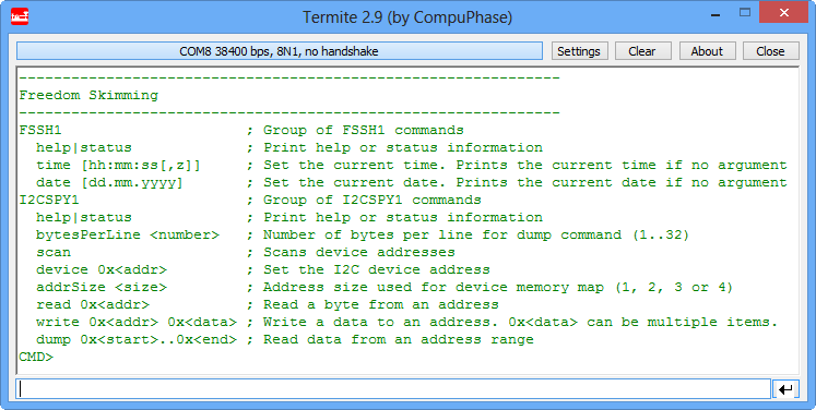
I2CSpy Shell Interface
Using the ‘scan’ command it will try all possible 7bit I2C addresses on the bus:
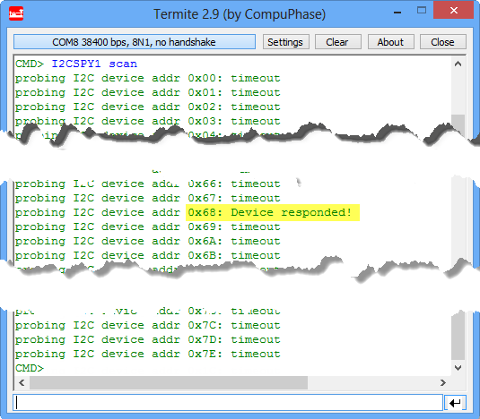
Scan Command to probe the bus
Then the ‘device’ command can be used to select an I2C address, and the dump or read command to read from the device:

Dumping I2C Device Memory
💡 The number of address bytes (1, 2, 3 or 4) can be set using the ‘addrSize’ command.
The number of bytes per line is configurable at runtime using the ‘bytesPerLine’ command:

BytesPerLine Command Example
Summary
The I2CSpy component is not only useful to spy out skimming devices. It can be used for pretty much any I2C device on the bus. Actually it is getting a standard component for my projects as it allows easily to read/write to I2C devices and to do advanced debugging. With this, that I2CSpy component has broader usage :-).
And yes: things are different from the original CSI television series. But still a lot of fun :razz:.
The I2CSpy Processor Expert component is available for download here.
Useful Links
- Articles about skimming devices: http://krebsonsecurity.com/category/all-about-skimmers/
- Google email list about physical mobile forensics: http://groups.google.com/group/physical-mobile-forensics?hl=en
- Research project Competence Center for Complex Digital Forensics, Gebert Rüf Foundation: http://www.grstiftung.ch/de/portfolio/projekte/alle/y_2011/GRS-060-11.html
Happy Spying 🙂

Hi,
Just saw on tv today that the police arrested around 100 persons involved in this kind of fraud.
Keep up the good work Erich! 🙂
Cristian
LikeLike
Pingback: Extended Driver for the MMA8451Q Accelerometer | MCU on Eclipse
Pingback: Device Driver for Freescale MAG3110 Digital Magnetometer | MCU on Eclipse
So these crook stick this gadget inside the card reader slot?
Is it not visible or cosmetically unusual to the users?
Amazing what crooks will do.
LikeLike
Yes, it is placed inside the card reader slot. If you do not pay close attention, then you will not see that there is an additional device in it which reads the card information 😦
LikeLike
Hi Erich,
Thank you again for another great tutorial! Now I understand how to configure the KL46 or KL25 for using I2C or USB CDC interfaces. But what about those situations where one needs to configure the clock routing to use UART, I2C, SPI and USB CDC ports all in one single application? Does one start bumping into clock speed limitations when this happens?
I have an application which reads from several sensors which are using UART, I2C and SPI ports. The acquired data is processed within the KL46 and the results are then sent to a computer using the USB CDC interface. I’m used to the comforts of achieving this goal on FPGAs. Usually on an FPGA you hav several PLL blocks where you can produce almost whatever clock frequencies you need to your heart’s content. Here on the Cortex-M0+ we have a fixed clocking architecture.
I can see the reasoning behind the way you are configuring the MCG and SIM modules in Processor Expert by following your USB CDC and I2C examples plus the KL46 and KL25’s clock distribution diagrams. I’m sure I’ll eventually figure something out by just taping the clocking diagrams on my office wall and then hitting my head against them for about a week. But nothing beats the wisdom from a seasoned Cortex-M0+ Jedi like yourself. It would also prevent me from irreversibly damaging my forehead 😉
What has been your general experience when trying to clock multiple interfaces on the Cortex-M0+? Are there common compromises or rules of thumb you follow?
Thanks and best regards,
Carlos
LikeLike
Hi Carlos,
yes, the number of timers and channels is limited. And in comparison to other devices on the market, the Freescale ones have not as many PWM signals. I never have enough, and end up to do software PWM for slower signals (not ideal). As for the timers: it is critical to understand the clock and channel concept (as you are getting aware by now 🙂 ). This is where Processor Expert helps me to quickly prototope the timers so I know which pins I can (or cannot) use. The thing to know is that the main clock of a timer affects all channels: they all share the same clock. Say with two timer blocks (TPM0 and TPM1), I can basically have two main clock settings, and the channels depend on it. For example I can use on TPM with a given frequency, and then all PWMs will have the same frequency (with different duty cycles).
As for the UARTS/I2C/SPI: similar thing here: the main clock drives things. if you need diffent speeds, you can consider to switch speed modes during the application: say you can run the I2C with 100 kHz for a slow device, and then shift gears for the 400 kHz device. For this, Processor Expert offers ‘clock modes’ or ‘speed modes’ so I can change the speed at runtime. But I avoid such situations as this only complicates things.
Last but not least: I started to use external devices if I cannot handle things which I cannot handle in the microcontroller because of lack of pins or channels (e.g. using I2C expanders). This is not ideal for large volume products, but a good way to reduce complexity (and damaging my forehead). Or for example to use a tiny microcontroller for dedicated puprposes. To give an example: For a robot I needed to drive multiple DC motors with H-Bridge and quadrature encoder. I simply had not enough PWM channels and timers on the main controller. So I decided to use multiple small microcontroller (1 KByte RAM, 8 KByte of Flash) which does that job and communicates over I2C with the main controller. This greatly somplified my design, and at the end was more cost effective than using a larger microcontroller. And I had more performance available in the main controller.
LikeLike
Hi Erich
I just have a question regarding the I2CSPY1_GetDeviceAddress() method.
I am using the FRDM KL25Z board with XTRINSIC development kit. The referenced component GI2C1 is configured as follows
LDD I2C
SDA PTE0
SCL PTE1
I am trying to use I2CSPY component to read addresses of connected devices to i2C1
I understand that the method I2CSPY1_GetDeviceAddress() for multiple devices has to be re-called 127 times. Whenever slave device sends an acknowledgment, I2CSPY1_GetDeviceAddress() will retun the address of slave? Am I correct?
Please see below my read out function. The addr variable is always 0.
Can you please advise what am I doing wrong?
Thanks in advance.
Kamil
uint8_t add,i;
I2CSPY1_Init();
for(i=0;i<127;i++){
add=I2CSPY1_GetDeviceAddress();
Term1_SendNum(add);
WAIT1_Waitms(50);
Term1_CRLF();
}
LikeLike
Hi Kamil,
GetDeviceAddress() only returns what you have specified earlier with SetDeviceAddress().
So to to read from multiple devices, do something like this:
SetDeviceAddress(0x10); /* select device with address 0x10 */
ReadRegData(0x30, &val16, sizeof(val16)); /* read two bytes from device previously selected (0x10) from address 0x30 of the device, and store the data in val16 */
I hope this helps,
Erich
LikeLike
Erich thanks for quick reply.
SetDeviceAddress and ReadRegData methods work for known addresses.
I wondered how to use I2CSPY component for scanning all I2C devices connected to I2C. Like shown
on the terminal window in your post. I configured shell component and Asynchro Serial.
How would look like the code for the I2C scan function?
Sorry I am newbee in the processor expert components.
Thanks for your help.
Kamil
LikeLike
Hi Kamil,
have a look at the implementation of ScanDevices() inside the I2CSpy component (used by the command line interface). Copied below:
static void ScanDevices(const CLS1_StdIOType *io) {

  uint8_t addr, oldAddr;

  uint8_t buf[3], res;
oldAddr = I2CSPY1_GetDeviceAddress();
for (addr=0; addrstdOut);
buf[0] = '';
UTIL1_strcatNum8Hex(buf, sizeof(buf), addr);
CLS1_SendStr(buf, io->stdOut);
if (I2CSPY1_SetDeviceAddress(addr)!=ERR_OK) {
CLS1_SendStr((unsigned char*)": failed selecting device\r\n", io->stdErr);
break; /* get out of for loop */
}
res = GI2C1_ScanDevice(addr);
if (res==ERR_NOTAVAIL) {
CLS1_SendStr((unsigned char*)": no ACK\r\n", io->stdErr);
} else if (res==ERR_OK) {
CLS1_SendStr((unsigned char*)": Device responded!\r\n", io->stdErr);
} else {
CLS1_SendStr((unsigned char*)": *** failed! ***\r\n", io->stdErr);
}
} /* for */
(void)I2CSPY1_SetDeviceAddress(oldAddr); /* restore old device address */
}
LikeLike
Erich
Thank you very much for complete solution. Now the implementation makes sense.
Thanks for your time.
Kamil
LikeLike
Hello Erich,
First, I really want to thank you for detailed explanation PE. I have learned a lot from you and I have real interest in KL25Z. I am enjoying it very much. However, currently I am having some issues. Your help would defintely keep me moving. I have been trying to connect a LIDAR LITE through i2c on a KL25Z. After using the PE files you created, I feel like I have a better grasp on it. However, I do not know the exact slave address for the LIDAR. And I cannot seem to get I2CSPY to run. I have the component and it has generated code. When I debug in CW, I get an CPU_interrupt. I am not sure what is causing debughalt();. Any help would be greatly appreciated. And again thank you.
Vishal
LikeLike
Hi Vishal,
I’m wondering why you don’t know the I2C address of your device: is this not noted in the data sheet?
Keep in mind that on the bus the I2C address is shifted, so make sure that the address you are using matches that.
Best if you test things with a logic analyzer.
Anyway, if yousing the scan method, make sure you are using the timeout component and setup the I2C component with a timeout.
As for the interrupt: make sure you configure the ‘own for every’ setting (see https://mcuoneclipse.com/2012/02/20/oh-my-an-interrupt/), then you will know what is triggering that interrupt.
I hope this helps,
Erich
LikeLike
Hi Erich, I am using two Processor Expert Components- EEPROM Driver I2C based and I2CSPY in conjunction with each other. On the scope I am seeing the I2C data being written on the EEPROM. I would like to dump the contents on hyperterminal as well.
This is the code that I am using at 38400 baud rate and 8N1 with no flow control.
I would like to know if this code is what I should be using.
Thanks.
res = EE241_WriteByte(0x0000, 0xa2a);
I2CSPY1_Init();
I2CSPY1_SetAddressSize(2);
//I2CSPY1_GetDeviceAddress();
I2CSPY1_SetDeviceAddress(0x00); /* select device with address 0x00 */
I2CSPY1_ReadRegData(0x0000, &val16, sizeof(val16));
The address size does it imply the memory of the EEPROM that I’m using 24LC32A or the address pins A0, A1 and A2 which is grounded in my case.
I am using UART0 pins A2 and A3 for communication with Tera Term.
LikeLike
You don’t have to go through the I2CSPY as you are already dealing with the EE241 directly. So simply read the values you need and write them to the console/terminal.
LikeLike
Hi Erich,
I have terminal connection established for displaying my EEPROM. The problem I am faced with is say my Cpu temperature is 29.5 degrees and I would like to display it on the hyperterminal as a float variable. While writing onto the EEPROM I am able to do it only byte by byte. i.e. i write 295 on my EEPROM and while reading it out and displaying it on my hyperterminal, I would like to display 29.5 instead of just 95 or 2 which is what is displayed right now. Also since there is only Readbyte on the EEPROM truncation takes place when I try writing a number bigger than 255. Is there a way to deal with this?
LikeLike
You can read multiple bytes and combine them to say 16 bit values, e.g.
uint16_t val16;
uint8_t val8a, val8b;
val8a = ReadByte();
val8b = ReadByte();
val16 = (val8a<<8)+val8b;
This is just basic C programming 🙂
LikeLike