
In my earlier Nokia LCD post I described a ‘free of charge’ way to add a LCD display to my FRDM-KL25Z board. If that Nokia display is not available, or an alphanumeric display is enough, then the Hitachi HD44780 display is a low cost option as well.
The HD44780 (or compatible) display is one of the most common displays available. And they usually conly costs around $10 or less. I have used a ‘blue’ 3.3V version of such a display already in my lectures with a Freescale S08 microcontroller. So I thought it would be nice to port the driver to the Kinetis and the KL25Z on it.

LCD Boards with FRDM-KL25Z
A recent post of TKJ Electronics about such a really inexpensive (only $5) HD44780 display caught my attention. And finally I had two of such TKJ displays in my postal mail box yesterday. Time to have some fun on a weekend 🙂
TKJ Electronics Display
The LCD from TKJ Electronics has no connector solderd, so this makes it convenient to solder my own ones. The small (66 mm x 27 mm) size makes it ideal for many applications.
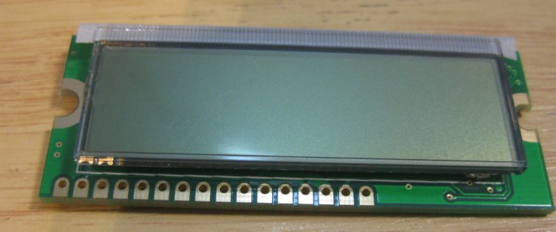
TKJ LCD Frontside
The display features two ‘half-holes’ on the side for easy mounting, e.g. for robotic applications.
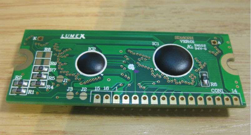
TKJ LCD Backside
The display is availble from http://shop.tkjelectronics.dk/.
Processor Expert LCD Component
To simplify usage of the LCD, I have written a Processor Expert component: LCDHTA. ‘HTA’ is the abbreviation of the University of Lucerne where I teach Embedded Systems Software. The LCDHTA offers the following methods:
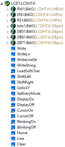
LCDHTA Methods
In the properties, the display settings are configured:
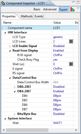
LCDHTA Properties
It supports both 4-bit and 8-bit data bus connection. If used in 4-bit mode, then DB4 to DB7 lines need to be connected. For the 8-bit mode, all data lines (DB0 to DB7) are connected.
4-bit LCD Mode
The following pins are supported in the component:
- LCD Enable (optional): used to select/deselect display if multiple displays are used
- RW (optional): Read/Write signal. Some displays have that pin which allows to read from the display. This is used to check if the display is busy or ready for new data.
- E (required): this ‘Enable’ signal is a strobe signal to start read/write operations.
- RS (required): Register Select, used to switch between command (RS=0) and data (RS=1) mode
- DBx (required): either 4 or 8 pins have to be assigned for the data/command bus.
The screenshot below shows the communication: first it reads from the LCD if it is ready (pulling down RS, then reading two 4-bit values). If ready, it pulls RS to HIGH level and puts the data on the bus. Then the data is transmitted with a Strobe signal on the E line:
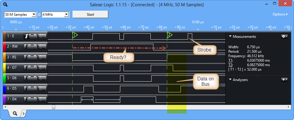
Communication Detail
In 4-bit mode, I used the following pin connections on the Freedom Board:
=================================================================
 SIGNAL LIST
-----------------------------------------------------------------
SIGNAL-NAME [DIR]        => PIN-NAME [PIN-NUMBER]
-----------------------------------------------------------------
DB4_D4 [I/O]             => TSI0_CH5/PTA4/I2C1_SDA/TPM0_CH1/NMI_b [30]
DB5_D5 [I/O]             => PTA5/USB_CLKIN/TPM0_CH2 [31]
DB6_D6 [I/O]             => CMP0_IN2/PTC8/I2C0_SCL/TPM0_CH4 [65]
DB7_D7 [I/O]             => CMP0_IN3/PTC9/I2C0_SDA/TPM0_CH5 [66]
E_D10 [Output]           => PTD0/SPI0_PCS0/TPM0_CH0 [73]
RS_D8 [Output]           => PTA13/TPM1_CH1 [33]
RW_D9 [Output]           => ADC0_SE6b/PTD5/SPI1_SCK/UART2_TX/TPM0_CH5 [78]
=================================================================
8-bit LCD Mode
While in 8-bit mode I used the following pin mapping:
=================================================================
 SIGNAL LIST
-----------------------------------------------------------------
SIGNAL-NAME [DIR]        => PIN-NAME [PIN-NUMBER]
-----------------------------------------------------------------
DB0_D0 [I/O]             => TSI0_CH2/PTA1/UART0_RX/TPM2_CH0 [27]
DB1_D1 [I/O]             => TSI0_CH3/PTA2/UART0_TX/TPM2_CH1 [28]
DB2_D2 [I/O]             => PTD4/LLWU_P14/SPI1_PCS0/UART2_RX/TPM0_CH4 [77]
DB3_D3 [I/O]             => PTA12/TPM1_CH0 [32]
DB4_D4 [I/O]             => TSI0_CH5/PTA4/I2C1_SDA/TPM0_CH1/NMI_b [30]
DB5_D5 [I/O]             => PTA5/USB_CLKIN/TPM0_CH2 [31]
DB6_D6 [I/O]             => CMP0_IN2/PTC8/I2C0_SCL/TPM0_CH4 [65]
DB7_D7 [I/O]             => CMP0_IN3/PTC9/I2C0_SDA/TPM0_CH5 [66]
E_D10 [Output]           => PTD0/SPI0_PCS0/TPM0_CH0 [73]
RS_D8 [Output]           => PTA13/TPM1_CH1 [33]
RW_D9 [Output]           => ADC0_SE6b/PTD5/SPI1_SCK/UART2_TX/TPM0_CH5 [78]
=================================================================
The blue LCD we use at the university is a true 3.3V one. So the supply voltage of this one is connected to the 3.3V on the FRDM-KL25Z board. The display needs about 10 mA for operation because of the backlight feature.
And here the LCD from TKJ Electronics gets really interesting, as the current needed for it is only 2-3 mA, but without backlight support. But that display needs 5V supply voltage. That 5V is provided from the Freedom board:
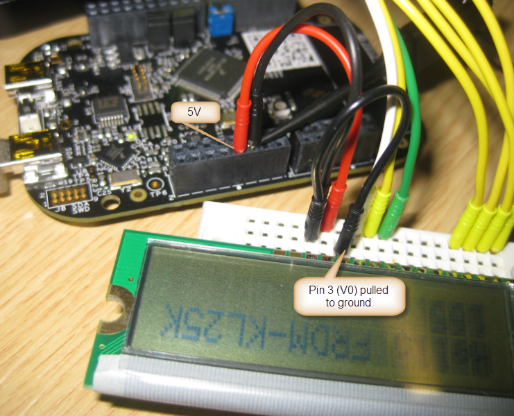
TKJ LCD Supply Details
The LCD Driving Voltage/Contast can be affected with a potentiometer (10-20k Ohm between Vdd and Vss to V0).
💡 Pulling V0 to Ground/GND is an easy way to avoid the potentiometer.
Software
Using the LCDHTA component, writing to the LCD is easy:
int main(void)
/*lint -restore Enable MISRA rule (6.3) checking. */
{
/* Write your local variable definition here */
/*** Processor Expert internal initialization. DON'T REMOVE THIS CODE!!! ***/
PE_low_level_init();
/*** End of Processor Expert internal initialization.                    ***/
/* Write your code here */
LCD1_Clear();
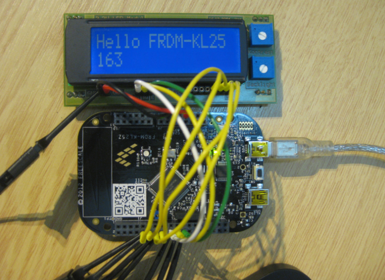
LCD1_WriteLineStr(1, "Hello FRDM-KL25K");
for(;;) {
uint8_t cnt;
uint8_t buf[5];
LCD1_GotoXY(2,1);
UTIL1_Num16uToStr(buf, sizeof(buf), cnt);
LCD1_WriteString((char*)buf);
cnt++;
WAIT1_Waitms(100);
}
/*** Don't write any code pass this line, or it will be deleted during code generation. ***/
/*** RTOS startup code. Macro PEX_RTOS_START is defined by the RTOS component. DON'T MODIFY THIS CODE!!! ***/
#ifdef PEX_RTOS_START
PEX_RTOS_START();                  /* Startup of the selected RTOS. Macro is defined by the RTOS component. */
#endif
/*** End of RTOS startup code.  ***/
/*** Processor Expert end of main routine. DON'T MODIFY THIS CODE!!! ***/
for(;;){}
/*** Processor Expert end of main routine. DON'T WRITE CODE BELOW!!! ***/
} /*** End of main routine. DO NOT MODIFY THIS TEXT!!! ***/
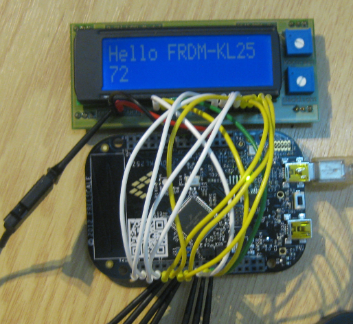
The above code writes a welcome message to the display and then increments a counter every 100 ms:

Hello on the TKJ Display
Summary
Using HD44780 displays with this Processor Expert component driver makes my life much easier. And having access to a broad range of inexpensive displays makes creating embedded systems projects even more fun.
The components are hosted on SourceForge, and example project (CodeWarrior) is on GitHub. The example project for Kinetis Design Studio is on GitHub here.
UPDATE: The latest version of the components are on SourceForge, see https://mcuoneclipse.com/2014/10/21/mcuoneclipse-releases-on-sourceforge/
Happy Displaying 🙂

I assume that, with everything being bitIO, the PEx component is universal, and can be used with, say, HCS08?
LikeLike
Yes, I use the displays it as well with HCS08 and ColdFire. There it is actually a little bit more efficient, as I can use BitsIO and ByteIO (there is a problem with using these for Kinetis).
LikeLike
Pingback: Tutorial: Ultrasonic Ranging with the Freedom Board | MCU on Eclipse
Thanks, excellent article and bean:)
LikeLike
I have an error due to “utility1”. It appears with a ‘X’. How I fix the problem.?
LikeLike
Could it be that you have not installed the Utility component. If you do not have a component, it is grayed out. You can download it from here: http://steinerberg.com/EmbeddedComponents/Utility/home.htm
LikeLike
Yes, you are right. However, after do this, I am still receiving the same error:
C:\Users\Lucio\workspace\Freedom_2x16_LCD\FLASH/../Project_Settings/Startup_Code/__arm_start.c:179: undefined reference to `__init_registers’
C:\Users\Lucio\workspace\Freedom_2x16_LCD\FLASH/../Project_Settings/Startup_Code/__arm_start.c:231: undefined reference to `__copy_rom_sections_to_ram’
C:\Users\Lucio\workspace\Freedom_2x16_LCD\FLASH/../Project_Settings/Startup_Code/__arm_start.c:251: undefined reference to `__init_cpp’
C:\Users\Lucio\workspace\Freedom_2x16_LCD\FLASH/../Project_Settings/Startup_Code/__arm_start.c:257: undefined reference to `__init_user’
c:/freescale/cw mcu v10.3/cross_tools/arm-none-eabi-gcc-4_6_2/bin/../lib/gcc/arm-none-eabi/4.6.2/../../../../arm-none-eabi/lib/armv6-m\libg.a(lib_a-exit.o): In function `exit’:
exit.c:(.text.exit+0x18): undefined reference to `_exit’
collect2: ld returned 1 exit status
mingw32-make: *** [Freedom_2x16_LCD.elf] Error 1
Inside of folder “Project Settings” –> “Startup Code” –> _”arm_start.c” appears with a ‘red X’ now.
LikeLike
Hello, looks like your startup code is missing. Maybe just zip your project and send it to ‘erich dot styger at hslu dot ch’ and I have a look?
LikeLike
Hi, Thanks! I just have sent it to you. I don’t know what happens, I only compile the example project of this page.
LikeLike
Hi, I have sent you another mail.with the new project. I have not problems but it doesn´t work. Could you check it please?
LikeLike
Hello, It looks like you are using MCU10.3 beta, while I’m on MCU10.3 (final). The thing is that the libraries have been changed from beta to final (final is using EWL libraries), so this is very likely the problem.
LikeLike
I’m having a problem when running the code, my LCD just show black boxes in the second line and nothing more, do you happen to know what could be wrong?
LikeLike
Hi Eduardo,
That sounds like the communication to the LCD does not work at all. Can you check your wiring/connections? Additionally it could be that you are too fast for your LCD. Try increasing the waiting time in the component settings. Step through the initialization code with the debugger (this slows down things too). Hope this helps.
LikeLike
Thank for the help, i did try to debug (sorry i’m a newbie i don’t really know much about MCU’s yet) i’m using a JHD162A display, perhaps that has something to do with it, i also triple checked the connections
LikeLike
Hi Eduardo,
I don’t know that JHD162A display, so I hope it is compatible with the command sets for the one I used in the post. But you might need to check the data sheet. I have seen some modules with different timing, so this might be a problem.
LikeLike
Indeed the problem seemed to be the wires i’ve been using to connect the LCD to freedom, thanks a lot!
LikeLike
Hi Eduardo,
good to hear that things have been sorted out!
LikeLike
I have the same problem, how exactly did you fix it? I’m using the same LCD but I’m using some jumper wires. Any info would help a lot.
LikeLike
Hi Jaime,
You mean the problem with the number of characters (not more than 16)? I had an email discussion with Kelvin, and updated the LCD component on GitHub (https://github.com/ErichStyger/mcuoneclipse) so it supports now any number of characters. For this I have added a property to the component so you can specify the number of characters (e.g. 20).
I hope this helps.
Erich
LikeLike
The problem I have is that the LCD only shows black boxes on one line. I’m using a 16×2 JHD162A LCD, so number of characters is the same. Thanks.
LikeLike
That very much looks like a wiring problem. Check carefully if you are using the right pins/connections. Then make sure that your wires are not too long (a few centimeters). The other thing is that you could increase the Wait(us) time in the component settings.
LikeLike
Yes, I just changed my jumpers to some shorter wires and it seems to work fine. Thanks a lot, this helped.
LikeLike
Cool! It really might depend on the display how long the wires could be, and how much noise you have.
LikeLike
Hi, can someone tell me how to configurate the component for a 2×20 LCD ?
LikeLike
Hi Kelvin,
is it using the HC44780 protocol, but just having 20 instead of 16 characters? If so, I could easily change the component. Do you have a link to the data sheet or any other reference?
LikeLike
We are trying to use this LCD for a proyect and it seems not working with this component, so please help us.
Click to access LCD2A20.PDF
LikeLike
Hi Biron,
at a glance, the display commands look compatible. Have you verified that your connection/wiring is correct? Are you using it in 8bit or 4bit mode?
What you can try is to set the ‘Wait (us)’ value in the display component. Maybe set it to 100, then it will wait 100 us before sending a command or data value.
The other thing you could try is to set the display type in the compenent settings from ‘generic’ to ‘DisplayTech 162c’: for this display I needed to wait 2 ms instead of 500 ns during the EnablePulse.
I hope this helps.
LikeLike
It works in this display, but the problem is that only 16 characters appear.
If you can tell us if it is possible change the code for put it in 2×20 characters display.
LikeLike
Hi,
It is possible to increase the number of lines?
For example, for a display of 4×16.
LikeLike
Yes, that should be doable. Do you have a link to the datasheet of the LCD you are using?
LikeLike
Yes, it is http://www.winstar.com.tw/download.php?ProID=30
I also tried to adapt the code to accept the package LCDHTA more than two lines but can not keep the changes. I do not know how to do it.
LikeLike
Ok, I’ll have a look. If you want to make your changes and make the code permanent, you need to implement this in the driver code (or using CDE (Component Development Environment), see https://mcuoneclipse.com/2013/03/31/tutorial-creating-a-processor-expert-component-for-an-accelerometer/
LikeLike
Hello,
I have updated the LCDHTA component so it supports now 3 and 4 line displays. As I do not have such a display, I’m not able to test it. I have commited the sources on GitHub, so can you try it out and give me feedback if this works for you?
LikeLike
Hello,
I have an appointment now. But as soon as I get back I will test and post the result.
LikeLike
no problem. I have sent you the component by email so you can try it out.
LikeLike
Hello,
It worked perfectly.
Thank you, is congratulated by Blog.
LikeLike
Excellent, thank you for your feedback 🙂
LikeLike
Pingback: Character LCD with 4 Lines | MCU on Eclipse
I’ve finally got around to getting this going. After some frustration, I discovered:
* The display I was using was only 1 line, addresses seem to be out, even when setting it as 1 line. (It also got upset about a FunctionSet_1Lines in LCD1.c – had to correct that to FunctionSet_1Line, but my version of the bean is the original, may be fixed by now.)
* Changing to a two-line display, I was just getting what look like Japanese characters: one of the four data wires was broken.
* Losing the first characters of the first line – had to bump the wait property all the way up to 1000us before this would work. (This is a write-only setup.) Note that this is also an HD44780 “compatible” display, so don’t know if this has any bearing on timings.
Many thanks for this, Erich, now I can get feedback through the LCD, I can get on to debugging the rest of the system!
LikeLike
Thanks for the note about FunctionSet_1Line: this was still wrong in my version. Now I have fixed it and committed it to the GitHub sources.
Abou the waiting time: yes, this is different from display to display. HC44780 pretty much only defines the commands, but not the timing of the protocol.
Thanks again for your feedback!
LikeLike
Another observation: for no reason that I can determine, changing code that in no way should impact the LCD code sees random garbage [mostly what looks like Japanese characters] appear in and around (sometimes before) the data I send out LCD1_WriteLineStr(). [The before scenario happened quite a lot: I’d get a consistent one or two characters BEFORE my string.]
The only thing I could think of that might impact this was the garbage already being in the buffer. I tried changing my line:
uint8_t buf[16];
to:
uint8_t buf[16] = {0};
So far, no garbage. But I haven’t made any changes elsewhere in the code since, so will continue to keep an eye on this, in case it’s not the full solution.
LikeLike
Yes, on power-up the display might contain random characters. Typically I overwrite the display RAM memory in my application at the beginning and do not rely on any content.
LikeLike
I’m getting the random characters when the system is running, rather than what’s on the LCD at startup. They’ll appear suddenly in the middle of the display. Now been running 7.5 hours since I added the buffer initialisation – no problems so far. Will have another play changing code elsewhere on Wednesday – this is when the problem started to manifest last time.
LikeLike
just to be clear: where did you do this buffer initialization? in your code or in the Processor Expert driver code?
LikeLike
In the first iteration of the main loop of ProcessorExpert.c, I invoke LCD1_Clear(). The initialisation of the buffer is performed in the function telltale() which gets called by an interrupt handler. (It’s displaying the value of a set of registers that will be driving a BCD clock.)
I haven’t made any modification to the generated LCD1.c
void telltale(void)

{

        uint8_t buf[16] = {0};
secsrun++;
UTIL1_strcatNum8u(buf, sizeof(buf), tNow.hTens);
UTIL1_strcatNum8u(buf, sizeof(buf), tNow.hOnes);
UTIL1_chcat(buf, sizeof(buf), ':');
UTIL1_strcatNum8u(buf, sizeof(buf), tNow.mTens);
UTIL1_strcatNum8u(buf, sizeof(buf), tNow.mOnes);
UTIL1_chcat(buf, sizeof(buf), ':');
UTIL1_strcatNum8u(buf, sizeof(buf), tNow.sTens);
UTIL1_strcatNum8u(buf, sizeof(buf), tNow.sOnes);
UTIL1_chcat(buf, sizeof(buf), ' ');
UTIL1_strcatNum16Hex(buf, sizeof(buf), secsrun);
LCD1_WriteLineStr(2, (char*)buf);
Heartbeat_Neg();
}
LikeLike
Hmmm, in my view it is a very bad thing to do things like writing to a LCD during an interrutp service routine. You get a lot of interrupt latency because of this. I rather suggest that you set a flag and then write text from your main application loop.
And yes, you need to initialize the buf[] array, otherwise this is a programming error. UTIL1_strcat adds a string to after the ” byte, and if you do not initialize the buffer, this will give you random results.
LikeLike
Is this an issue when the ISR only fires every second? I’ll move to the flag-setting approach, as good practice, but just curious.
LikeLike
It is just that writing to the LCD is not very fast, thus blocks other interrupts. Plus in case you write from other code to the display, you need to make sure things are re-entrant.
LikeLike
I’m not entirely sure how to make the functions re-entrant if they are triggered by the presence of a global flag, but I’ve changed my code to work like this:
* ISRs to only do “low-level” stuff: logical operations, set variables (set to a specific value, or increment/decrement.)
* All more complex operations that were in ISRs are invoked from the main loop in ProcessorExpert.c, by checking for a flag being set (by the ISRs, etc,) doing whatever is required, then un-setting the flag.
Does that sound more reasonable?
LikeLike
Yes, that sounds more reasonable. Just make sure that your flag is volatile, like
volatile bool msgToLCD;
In case you have many such event flags, then have a look at the ‘SimpleEvents’ Processor Expert module I have created. It manages an array of bits for this kind of things in a reentrant way.
With SetEvent(event) you can set an event, and with GetEvent() or HandleEvent() you can check the event flags.
Let me know if you need an example or more information.
LikeLike
Thanks, Erich! I’ll certainly have a look at this, as I’ve been using a system status struct – and adding members all the time, which I have to remember to initialise. Some magic that can hide all that would be good 🙂
LikeLike
HI Erich
I was watching your projects and there are very interesting, but I just want to tell you,I took your lcd project and modify to make it serial using the SPI module and a 595, I could give you the libraries with the small modifications I did and you share with others, but also I would like to I attach the changes in the component of PEX but I’m in the ending of my semester and I’m very busy.
LikeLike
Hi Antonio,
you could send my your file(s) and I should be able to integrate your changes, if that’s ok with you.
Erich
LikeLike
Ok, I will share with you my files and small tutorial, what is your email or how do I share it with you?
LikeLike
My email address is on the about page of this blog (bottom of the pag).
LikeLike
Oohhh yaaaa sorry I’m a fool.
LikeLike
Pingback: Character LCD with 4 Lines and up to 64 Characters per Line | MCU on Eclipse
Excellent items for the KL25Z. I am trying to used the code you have posted and I am having trouble getting the text to display on the LCD. The lcd I am using is https://www.sparkfun.com/datasheets/LCD/GDM1602K-Extended.pdf. Any suggestions. I am downloaded the LCD, Wait, and until components, made sure the pin connection match to the pin I/O. No trouble building the project or running the project, just will not display any text.
LikeLike
Really hard to tell from remote, without having one of these LCD’s. Is the backlight ok? As well the contrast settings? Are you using the R/W signal? Otherwise I suggest to increase the delay time in the component to make the communication slower. You might single step through the initialization code of the LCD with the debugger: this slows down things and maybe then you see something on the display.
In any case: hook up a logic analyzer to the signals and check what is going on on the wires.
LikeLike
I enjoyed this tutorial. It has helped to understand some of the mechanics of the IDE and using PE. Thanks for the excellent work.
LikeLike
Hi Mike,
glad to hear that this was useful for you :-). There is a follow-up article on that topic too:
LikeLike
i have this shield for arduino: http://www.droboticsonline.com/index.php/arduino-lcd-keypad-shield.html
when I use this component my LCD just show black boxes in the firt line and nothing more, do you happen to know what could be wrong?
LikeLike
With which board are you using this LCD? If you are going to use it with the FRDM board, then I think it will not work, as this LCD is a 5V one (according to the information in the link you provided). What you need is a display which is compatible with 3.3V of the FRDM board. Using a 5V display with a 3.3V system can in the worst case damage your hardware: you need to use a proper 3.3V display or level shifters.
LikeLike
I had not set the pins correctly, now is working, do you think I can damage the board using this display?
LikeLike
Yes. Especially if you are conneting 5V output pins with 3.3V input pins.
LikeLike
Thanks, I tested the display feeding him with 3.3 V and it worked. I will use it in unbonded direntamente plate making wired connections. I will adjust the reading of the buttons, there was a button that was before generating 3.6V. Now I think I can use without fear with this new arrangement.
LikeLike
hello! you have a great page, but I have a question:
I’m doing a project and I need print in a lcd decimal numbers, for example: 0.2, 1.4, 5.5, etc. Could you help me with these?
LikeLike
What is the type of your number?
I usually use the Utility component for this, something like (out of my head):
unsigned char buf[32];
uint8_t deciGrade; /* temperature in deci grade, e.g. 235 means 23.5 degree */
buf[0] = ”;
UTIL1_strcatNum8u(buf, sizeof(buf), deciGrade/10);
UTIL1_chcat(buf, sizeof(buf), ‘.’);
UTIL1_strcatNum8u(buf, sizeof(buf), deciGrade%10);
LikeLike
the number is a variable that i’ll changin it while the program is runing. May you please make some really fast video about this?
LikeLike
Creating a video is a very time consuming task.
But that example works with any variable, independent if you are changing it while the program runs.
I do not see that this would be an issue?
LikeLike
Hello,
Great bean as always!
I’m using this bean and several others you have created in my serial diagnostic
device I am building.
One question though, I see you like to use pta4 for a data line on the LCD.
I’d like to use it as well, but i have a interference with the NMI (non maskable interrupt) for the CPU that is also on pta4.
Is it safe to pin share this? or disable nmi?
Thanks again!
-Ben
LikeLike
Hi Ben,
I use this pin as sometimes I do not have anything left on my FRDM headers. If you are using PTA4, then you need to disable the NMI interrupt in the CPU component (you cannot share it).
LikeLike
Hi,
I try to control my LCD screen (ref FDCC1601E-FLYYBW-91LE) with my tower K70.
The link for the datasheet : http://www.farnell.com/datasheets/653649.pdf
The connection are :
• PTC0 = DB0 connected to pin 7 LCD screen
• PTC1= DB1 connected to pin 8 LCD screen
• PTC2 = DB2 connected to pin 9 LCD screen
• PTC3 = DB3 connected to pin 10 LCD screen
• PTC4 = DB4 connected to pin 11 LCD screen
• PTC5 = DB5 connected to pin 12 LCD screen
• PTC6 = DB6 connected to pin 13 LCD screen
• PTC7 = DB7 connected to pin 14 LCD screen
• PTC8 = RS connected to pin 4 LCD screen
• PTC9 = R/W connected to pin 5 LCD screen
• PTC10 = E connected to pin 6 LCD screen
I did the software with the GPIOs and I follow the initialization (page 16/20).
It displayed in my screen 8 black characters into 8 first places and nothing after.
Could you help me please?
Thank you.
Please find below my software.
/***********************************************************************/
/*Initialisation de l’écran LCD */
/***********************************************************************/
E_LCD_ClrVal(E_LCD_DeviceData);
RW_LCD_ClrVal(RW_LCD_DeviceData);
RS_LCD_ClrVal(RS_LCD_DeviceData);
tempo(10);
tempo(100);
tempo(1000); //500µs
tempo(10000); //6ms
for(int i=0; i<20; i++)
{
tempo(10000); //6ms
}
functionSet_LCD(8, 1,format5x8);
tempo(10000); //6ms
functionSet_LCD(8, 1,format5x8);
tempo(10000); //6ms
functionSet_LCD(8, 1,format5x8);
tempo(10000); //6ms
displayOnOffControl_LCD(DISPLAY_OFF, CURSOR_OFF, CURSOR_BLINK_OFF);
tempo(10000); //6ms
clearDisplay_LCD();
tempo(10000); //6ms
entryModeSet_LCD(INC, SHIFT_ON);
tempo(10000); //6ms
displayOnOffControl_LCD(DISPLAY_ON, CURSOR_ON, CURSOR_BLINK_ON);
/***********************************************************************/
for(;;)
{
/***************************************/
/*Affichage sur l'écran LCD */
/***************************************/
setDdramAddress_LCD(0,0,0,0,0,0,0); // Adresse 0H
tempo(10000); //6ms
writeData_LCD(0,0,1,1,0,0,0,0); //Chiffre 0
tempo(10000); //6ms
writeData_LCD(0,0,1,1,0,0,0,1); //Chiffre 1
tempo(10000); //6ms
writeData_LCD(0,0,1,1,0,0,1,0); //Chiffre 2
/***************************************/
}
void setCgramAddress_LCD(char AC5, char AC4, char AC3, char AC2, char AC1, char AC0)
{
E_LCD_ClrVal(E_LCD_DeviceData);
RW_LCD_ClrVal(RW_LCD_DeviceData);
RS_LCD_ClrVal(RS_LCD_DeviceData);
tempo(100);
/********Front Montant*********/
E_LCD_ClrVal(E_LCD_DeviceData);
E_LCD_SetVal(E_LCD_DeviceData);
/******************************/
if(AC0 == 0)
{
DB0_LCD_ClrVal(DB0_LCD_DeviceData);
}
else
{
DB0_LCD_SetVal(DB0_LCD_DeviceData);
}
if(AC1 == 0)
{
DB1_LCD_ClrVal(DB1_LCD_DeviceData);
}
else
{
DB1_LCD_SetVal(DB1_LCD_DeviceData);
}
if(AC2 == 0)
{
DB2_LCD_ClrVal(DB2_LCD_DeviceData);
}
else
{
DB2_LCD_SetVal(DB2_LCD_DeviceData);
}
if(AC3 == 0)
{
DB3_LCD_ClrVal(DB3_LCD_DeviceData);
}
else
{
DB3_LCD_SetVal(DB3_LCD_DeviceData);
}
if(AC4 == 0)
{
DB4_LCD_ClrVal(DB4_LCD_DeviceData);
}
else
{
DB4_LCD_SetVal(DB4_LCD_DeviceData);
}
if(AC5 == 0)
{
DB5_LCD_ClrVal(DB5_LCD_DeviceData);
}
else
{
DB5_LCD_SetVal(DB5_LCD_DeviceData);
}
DB6_LCD_SetVal(DB6_LCD_DeviceData);
DB7_LCD_ClrVal(DB7_LCD_DeviceData);
tempo(100);
/********Front Descendant*********/
E_LCD_ClrVal(E_LCD_DeviceData);
/********************************/
}
void setDdramAddress_LCD(char AC6, char AC5, char AC4, char AC3, char AC2, char AC1, char AC0)
{
E_LCD_ClrVal(E_LCD_DeviceData);
RW_LCD_ClrVal(RW_LCD_DeviceData);
RS_LCD_ClrVal(RS_LCD_DeviceData);
tempo(100);
/********Front Montant*********/
E_LCD_ClrVal(E_LCD_DeviceData);
E_LCD_SetVal(E_LCD_DeviceData);
/******************************/
if(AC0 == 0)
{
DB0_LCD_ClrVal(DB0_LCD_DeviceData);
}
else
{
DB0_LCD_SetVal(DB0_LCD_DeviceData);
}
if(AC1 == 0)
{
DB1_LCD_ClrVal(DB1_LCD_DeviceData);
}
else
{
DB1_LCD_SetVal(DB1_LCD_DeviceData);
}
if(AC2 == 0)
{
DB2_LCD_ClrVal(DB2_LCD_DeviceData);
}
else
{
DB2_LCD_SetVal(DB2_LCD_DeviceData);
}
if(AC3 == 0)
{
DB3_LCD_ClrVal(DB3_LCD_DeviceData);
}
else
{
DB3_LCD_SetVal(DB3_LCD_DeviceData);
}
if(AC4 == 0)
{
DB4_LCD_ClrVal(DB4_LCD_DeviceData);
}
else
{
DB4_LCD_SetVal(DB4_LCD_DeviceData);
}
if(AC5 == 0)
{
DB5_LCD_ClrVal(DB5_LCD_DeviceData);
}
else
{
DB5_LCD_SetVal(DB5_LCD_DeviceData);
}
if(AC6 == 0)
{
DB6_LCD_ClrVal(DB6_LCD_DeviceData);
}
else
{
DB6_LCD_SetVal(DB6_LCD_DeviceData);
}
DB7_LCD_SetVal(DB7_LCD_DeviceData);
tempo(100);
/********Front Descendant*********/
E_LCD_ClrVal(E_LCD_DeviceData);
/********************************/
}
void writeData_LCD(char D7, char D6, char D5, char D4, char D3, char D2, char D1, char D0)
{
E_LCD_ClrVal(E_LCD_DeviceData);
RW_LCD_ClrVal(RW_LCD_DeviceData);
RS_LCD_SetVal(RS_LCD_DeviceData);
tempo(100);
/********Front Montant*********/
E_LCD_ClrVal(E_LCD_DeviceData);
E_LCD_SetVal(E_LCD_DeviceData);
/******************************/
if(D0 == 0)
{
DB0_LCD_ClrVal(DB0_LCD_DeviceData);
}
else
{
DB0_LCD_SetVal(DB0_LCD_DeviceData);
}
if(D1 == 0)
{
DB1_LCD_ClrVal(DB1_LCD_DeviceData);
}
else
{
DB1_LCD_SetVal(DB1_LCD_DeviceData);
}
if(D2 == 0)
{
DB2_LCD_ClrVal(DB2_LCD_DeviceData);
}
else
{
DB2_LCD_SetVal(DB2_LCD_DeviceData);
}
if(D3 == 0)
{
DB3_LCD_ClrVal(DB3_LCD_DeviceData);
}
else
{
DB3_LCD_SetVal(DB3_LCD_DeviceData);
}
if(D4 == 0)
{
DB4_LCD_ClrVal(DB4_LCD_DeviceData);
}
else
{
DB4_LCD_SetVal(DB4_LCD_DeviceData);
}
if(D5 == 0)
{
DB5_LCD_ClrVal(DB5_LCD_DeviceData);
}
else
{
DB5_LCD_SetVal(DB5_LCD_DeviceData);
}
if(D6 == 0)
{
DB6_LCD_ClrVal(DB6_LCD_DeviceData);
}
else
{
DB6_LCD_SetVal(DB6_LCD_DeviceData);
}
if(D7 == 0)
{
DB7_LCD_ClrVal(DB7_LCD_DeviceData);
}
else
{
DB7_LCD_SetVal(DB7_LCD_DeviceData);
}
tempo(100);
/********Front Descendant*********/
E_LCD_ClrVal(E_LCD_DeviceData);
/********************************/
}
void clearDisplay_LCD()
{
E_LCD_ClrVal(E_LCD_DeviceData);
RW_LCD_ClrVal(RW_LCD_DeviceData);
RS_LCD_ClrVal(RS_LCD_DeviceData);
tempo(100);
/********Front Montant*********/
E_LCD_ClrVal(E_LCD_DeviceData);
E_LCD_SetVal(E_LCD_DeviceData);
/******************************/
DB0_LCD_SetVal(DB0_LCD_DeviceData);
DB1_LCD_ClrVal(DB1_LCD_DeviceData);
DB2_LCD_ClrVal(DB2_LCD_DeviceData);
DB3_LCD_ClrVal(DB3_LCD_DeviceData);
DB4_LCD_ClrVal(DB4_LCD_DeviceData);
DB5_LCD_ClrVal(DB5_LCD_DeviceData);
DB6_LCD_ClrVal(DB6_LCD_DeviceData);
DB7_LCD_ClrVal(DB7_LCD_DeviceData);
tempo(100);
/********Front Descendant*********/
E_LCD_ClrVal(E_LCD_DeviceData);
/********************************/
}
void returnHome_LCD()
{
E_LCD_ClrVal(E_LCD_DeviceData);
RW_LCD_ClrVal(RW_LCD_DeviceData);
RS_LCD_ClrVal(RS_LCD_DeviceData);
tempo(100);
/********Front Montant*********/
E_LCD_ClrVal(E_LCD_DeviceData);
E_LCD_SetVal(E_LCD_DeviceData);
/******************************/
DB0_LCD_SetVal(DB0_LCD_DeviceData);
DB1_LCD_SetVal(DB1_LCD_DeviceData);
DB2_LCD_ClrVal(DB2_LCD_DeviceData);
DB3_LCD_ClrVal(DB3_LCD_DeviceData);
DB4_LCD_ClrVal(DB4_LCD_DeviceData);
DB5_LCD_ClrVal(DB5_LCD_DeviceData);
DB6_LCD_ClrVal(DB6_LCD_DeviceData);
DB7_LCD_ClrVal(DB7_LCD_DeviceData);
tempo(100);
/********Front Descendant*********/
E_LCD_ClrVal(E_LCD_DeviceData);
/********************************/
}
void entryModeSet_LCD(char incDec, char shiftOfEntireDisplay)
{
E_LCD_ClrVal(E_LCD_DeviceData);
RW_LCD_ClrVal(RW_LCD_DeviceData);
RS_LCD_ClrVal(RS_LCD_DeviceData);
tempo(100);
/********Front Montant*********/
E_LCD_ClrVal(E_LCD_DeviceData);
E_LCD_SetVal(E_LCD_DeviceData);
/******************************/
if(shiftOfEntireDisplay == SHIFT_ON)
{
DB0_LCD_SetVal(DB0_LCD_DeviceData);
}
else
{
DB0_LCD_ClrVal(DB0_LCD_DeviceData);
}
if(incDec == INC)
{
DB1_LCD_SetVal(DB1_LCD_DeviceData);
}
else
{
DB1_LCD_ClrVal(DB1_LCD_DeviceData);
}
DB2_LCD_SetVal(DB2_LCD_DeviceData);
DB3_LCD_ClrVal(DB3_LCD_DeviceData);
DB4_LCD_ClrVal(DB4_LCD_DeviceData);
DB5_LCD_ClrVal(DB5_LCD_DeviceData);
DB6_LCD_ClrVal(DB6_LCD_DeviceData);
DB7_LCD_ClrVal(DB7_LCD_DeviceData);
tempo(100);
/********Front Descendant*********/
E_LCD_ClrVal(E_LCD_DeviceData);
/********************************/
}
void displayOnOffControl_LCD(char displayOnOff, char cursorOnOff, char cursorBlink)
{
E_LCD_ClrVal(E_LCD_DeviceData);
RW_LCD_ClrVal(RW_LCD_DeviceData);
RS_LCD_ClrVal(RS_LCD_DeviceData);
tempo(100);
/********Front Montant*********/
E_LCD_ClrVal(E_LCD_DeviceData);
E_LCD_SetVal(E_LCD_DeviceData);
/******************************/
if(cursorBlink == CURSOR_BLINK_ON)
{
DB0_LCD_SetVal(DB0_LCD_DeviceData);
}
else
{
DB0_LCD_ClrVal(DB0_LCD_DeviceData);
}
if(cursorOnOff == CURSOR_ON)
{
DB1_LCD_SetVal(DB1_LCD_DeviceData);
}
else
{
DB1_LCD_ClrVal(DB1_LCD_DeviceData);
}
if(displayOnOff == DISPLAY_ON)
{
DB2_LCD_SetVal(DB2_LCD_DeviceData);
}
else
{
DB2_LCD_ClrVal(DB2_LCD_DeviceData);
}
DB3_LCD_SetVal(DB3_LCD_DeviceData);
DB4_LCD_ClrVal(DB4_LCD_DeviceData);
DB5_LCD_ClrVal(DB5_LCD_DeviceData);
DB6_LCD_ClrVal(DB6_LCD_DeviceData);
DB7_LCD_ClrVal(DB7_LCD_DeviceData);
tempo(100);
/********Front Descendant*********/
E_LCD_ClrVal(E_LCD_DeviceData);
/********************************/
}
void functionSet_LCD(char interfaceData, char nbrLine, char fontType)
{
E_LCD_ClrVal(E_LCD_DeviceData);
RW_LCD_ClrVal(RW_LCD_DeviceData);
RS_LCD_ClrVal(RS_LCD_DeviceData);
tempo(100);
/********Front Montant*********/
E_LCD_ClrVal(E_LCD_DeviceData);
E_LCD_SetVal(E_LCD_DeviceData);
/******************************/
if(fontType == format5x8)
{
DB2_LCD_ClrVal(DB2_LCD_DeviceData);
}
else
{
DB2_LCD_SetVal(DB2_LCD_DeviceData);
}
if(nbrLine == 1)
{
DB3_LCD_ClrVal(DB3_LCD_DeviceData);
}
else
{
DB3_LCD_SetVal(DB3_LCD_DeviceData);
}
if(interfaceData == 8)
{
DB4_LCD_SetVal(DB4_LCD_DeviceData);
}
else
{
DB4_LCD_ClrVal(DB4_LCD_DeviceData);
}
DB5_LCD_SetVal(DB5_LCD_DeviceData);
DB6_LCD_ClrVal(DB6_LCD_DeviceData);
DB7_LCD_ClrVal(DB7_LCD_DeviceData);
tempo(100);
/********Front Descendant*********/
E_LCD_ClrVal(E_LCD_DeviceData);
/********************************/
}
void tempo(int j)
{
DEBUG_TEMPO_SetVal(DEBUG_TEMPO_DeviceData);
for(int i=0;i<j; i++)
{
__asm("nop");
}
DEBUG_TEMPO_ClrVal(DEBUG_TEMPO_DeviceData);
}
LikeLike
Hi Armando,
and why are you not using the component I have created? It took me a very long time to get the timing right and correctly working. So if you start from scratch, it seems that you are facing yourself all these problems. So I suggest that you use that component code, instead creating your own version. Be free then to change it your own version, but I think it is much easier to start with something working? I hope this helps,
Erich
LikeLike
How do I use special character?
LikeLike
Have you seen the LoadSoftChar() method of the driver? There is an example in it how you can define your custom character.
Erich
LikeLike
I have seen, but I’m having trouble using.
LikeLike
I managed to use.
This with this notice.
LCD1_LoadSoftChar(0,&SoftCharUE[0]);
passing argument 2 of ‘LCD1_LoadSoftChar’ discards ‘const’ qualifier from pointer target type [enabled by default] ProcessorExpert.c /Freedom_2x16_LCD/Sources line 111 C/C++ Problem
LikeLike
Hi José,
you need to cast the parameter to (unsigned char*) to get rid of the warning.
Erich
LikeLike
I did what I was told.
It all worked out, this library is wonderful.
Thank you very much.
Now I have a graphic display 128/64 would have a library for this?
This site is very good.
Thank you very much.
LikeLike
Yes, I do have a graphic library for graphic displays, see https://mcuoneclipse.com/2012/12/16/zero-cost-84×48-graphical-lcd-for-the-freedom-board/.
I have it for a few displays, that Nokia, for a Siemens S64 and for the TWR-LCD.
LikeLike
My display is RoHS MGD12864H.
It is poss………
LikeLike
Everyting is possible (with the right amount of time). But I don’t have a driver for that one 😦
LikeLike
Okay, I’m studying his library and I’m datasheet LCD.
I’ll try.
Thank you very much.
LikeLike
Hey Erich,
I am getting an error in the given line of the above mentioned code
UTIL1_Num16uToStr(buf, sizeof(buf), cnt);
The error is – Undefined reference to UTIL1_Num16uToStr
Can you please help ?
Thanks
LikeLike
Hi Saransh,
do you have the utility module/component present in your project? Otherwise it seems that you might use old/outdated components/projects? The latest components are available on SourceForge, see https://mcuoneclipse.com/2014/10/21/mcuoneclipse-releases-on-sourceforge/
I hope this helps,
Erich
LikeLike
Hi,
I have two displays, at first it works perfectly but on second display it shows only black boxes, but in both lines. The difference between display is, that first is 1602E v1.1 and second which does not work is 1602A v2.0. I checked wires and increase cycles in function WAIT1_Waitms from 1000 to 10000, but it still does not work. Do you have any tips?
Thanks.
LikeLike
Hi Sumi,
probably the timing is different. I suggest you check the LCD1.c (generated) sources. There are several timing defines in there, e.g.
#define Timing_PWeh_ns 230 /* PWeh: Enable Pulse width (high level) */
#define Timing_tAS_ns 40 /* tAB: Address set-up time (RS, RW to E ) */
#define Timing_tDDR_ns 160 /* tDDR: Data delay time */
#define Timing_tCYCLE_ns 500 /* tCYLE: Enable Cycle time */
You might increase these numbers. Otherwise: can you single step through your code and have a logic analyzer attached to your hardware so you see what is going on?
LikeLike
Good Evening Mr Styger I stuck for a little more than an hour trying to install the LCDHTA program but I haven’t been successful. Can you plese explain me how I can achieve that. I will really appreciate it.
German C.
LikeLike
Hi German,
so what is the problem? ‘Installation’ of a project in Eclipse is done with File > Import > Import existing project into workspace.
LikeLike
After downloaded the custom character (ê), is possible use it with LCD1_write?
the CGRAM position is of custom chacarter is 0x00.
LCD1_WriteLineStr(1, “My ê mensage”); how can i put this custom character in the function “ê”?
LikeLike
Hi Gabriel, have you loaded your custom character to the ‘charCode’ ASCII value of ‘ê’:
void LCD1_LoadSoftChar(byte charCode, byte *softChar)
?
Then you can use it with LCD1_WriteLineStr(1, “My ê mensage”);
LikeLike
Hi Erich,
First, i defined the custom (ã) character with:
const byte Til_a[8] = {0x16,0x09,0x0E,0x01,0x0F,0x11,0x0F,0x00};
and then,
void Program_disp(void){
LCD1_WriteLCDCommand(0x40);
for (i=0; i<=7; i++){ //send ã
LCD1_Write(Til_a[i]);
}
}
But, when i use LCD1_WriteLineStr(1, “Tensão”) the LCD doesn't show "ã".
PS:Tensão means voltage (portugues)
LikeLike
Hi Gabriel,
you need to do this:
static const byte Til_a[8] = {0x16,0x09,0x0E,0x01,0x0F,0x11,0x0F,0x00};
then call
LCD1_LoadSoftChar(‘ã’, &Til_a[0]);
Now you can use it e.g. with
LCD1_WriteLineStr(1, “Tensão”);
I hope this helps,
Erich
LikeLike
HI Erich,
I tried to use the LDCHTA component on my KDS (version 3.0) and with a FRDM-KL25Z, but when I want to change settings on the component I have multiples errors saying that “The component is not supported for selected processor”…do you have an idea of where the problem could come from?
PS: I checked twice and I initialised well my project with the KL25Z128
LikeLike
Hi Yohan, it seems to me that you have created a project with the Kinetis SDK enabled? Keep in mind that using the Kinetis SDK is not compatible with all the available components, except the special fsl_ ones. Create the project with the SDK option set to ‘none’.
I hope this helps.
LikeLike
Yes indeed, I changed the project with only PE and it compiles, however I still run into some issues when I debug my program, it doesn’t pass through the LCD1Init function in the PE_low_level_init() .
LikeLike
I’m affraid that you have to debug through that function and identify what is going wrong. The logic analyzer should help you too to inspect the signals.
LikeLike
Is it possible to write a function like lcd_printf(“……%d”, …..); ?
LikeLike
Yes, this is certainly possible (you can use the normal C va_arg makros to implement something like this).
But my preference would not to use something like this, as using open argument lists and printf() style in general is not a good thing, see https://mcuoneclipse.com/2013/04/19/why-i-dont-like-printf/
LikeLike
Hi Erich,
I’m trying to use the LCDHTA component with KDS 3.0, but when building the project appears an error in WAIT1.c file:
undefined reference to ‘asm’
Do you have an idea of where the problem could come from?
Best Regards,
Wesley
LikeLike
Hi Wesley,
could it be that you are using an old/outdated version of the component? The latest versions are on SourceForge (see https://mcuoneclipse.com/2014/10/21/mcuoneclipse-releases-on-sourceforge/). The old version of the Wait component had asm() in it, but this has been replaced with the more portable __asm() long time ago.
Let me know if this is your problem.
Thanks,
Eric
LikeLike
Hi Wesley,
oh, I see now where the problem comes from: this article still links to the old (original) components. I have updated the post. Sorry for that!
Erich
LikeLike
G’day Erich,
Thanks for your work on your LCD component!
I’m just starting out with KDS, and have got v3.1.0 installed. I’ve got your latest components installed, also, and am trying to build your example project. It doesn’t seem to build though, I only get
**** Clean-only build of configuration FLASH for project Freedom_2x16_LCD ****
make clean
make: *** No rule to make target `clean’. Stop.
Looking at the project properties, I’m seeing a lot of ‘…orphaned…’ warnings around the place. For instance, under C/C++ Build -> Tool Chain Editor, under Configuration I have
Orphaned configuration. No base extension cfg exists for org.eclipse.cdt.cross.arm.gnu.sourcery.windows.elf.debug.784994391
Under Current toolchain I see
Orphaned toolchain org.eclipse.cdt.cross.arm.gnu.sourcery.windows.elf.toolchain.debug.2056576785 (ARM Ltd Windows GCC (G++ Lite))
While under current builder I see
Orphaned builder org.eclipse.cdt.cross.arm.gnu.sourcery.windows.elf.builder.debug.861107585 (ARM Ltd Windows GNU Make builder)
I’m not sure what to do from here, have you seen this previously? How would I go about fixing it?
Kind regards,
Stephen
LikeLike
Hi Stephen,
it looks to me that you have loaded a CodeWarrior project and not a Kinetis Design Studio project? Which project did you load?
Erich
LikeLike
Ah, that might do it, you think? I got the example from the link in your summary [“…an example project here.”].
I extracted the archive Freedom_2x16_LCD.zip, fired up KDS, File -> Import, General -> Existing Projects into Workspace. I clicked Next, browsed for the root directory, found the location of the extracted archive, and clicked OK.
At this point, the Projects pane showed only the Freedom_2x16_LCD project, and I hit Finish.
Was this the right way to go about it? If not, how would you recommend I try again?
Thanks again for your help, it’s very much appreciated!
LikeLike
Oh, I see. That is indeed a CodeWarrior project (rather old). I have update the link to a newer version on GitHub (for CodeWarrior too). I don’t have the same for KDS. Should not be a big deal, but it does not exist yet 😦 Sorry for that.
LikeLike
Ah, fair enough. Well, if you do end up putting together an example for KDS I’d love to hear it, in the meantime I’ll keep trying myself.
Kind regards,
Stephen
LikeLike
Hi Stephen,
I see if I can do the port to KDS tonight.
LikeLike
Hi Stephen,
I have ported the project to KDS here: https://github.com/ErichStyger/mcuoneclipse/tree/master/Examples/KDS/FRDM-KL25Z/FRDM-KL25Z_2x16_LCD
I have not tried it on hardware, but I think it should work. Otherwise please let me know and I have a look.
Erich
LikeLike
Thanks Erich, much appreciated! I’ll download it now and give it a go sometime through the day.
LikeLike
Hi Erich,
I’m using KDS with Processor Expert to add the LCDHTA module. Unfortunately I can’t create a project in KDS that includes the base Processor Expert modules such as the BitIO.
The E and RS signals allow using your GenericBitIO module however the Data/Control Bus requires to use the BItIO module. Is there any way to use GenericBitIO instead?
Thanks,
Dan
LikeLike
Hi Dan,
it seems to me that you have created a project with the Kinetis SDK enabled. Such a project does not allow you to add the BitIO component. Create a new project with the Kinetis SDK not included/disabled, then you can use the BitIO.
I hope this helps,
Erich
LikeLike
Unfortunately I’m using a KL27Z and it isn’t directly supported through Processor Expert – only with the KSDK. Is there any way around this without switching boards?
LikeLike
The easiest way is to switch boards. Or you create a project with Processor Expert say for the KL25Z128, then add the component, create the code and then copy the code to the KL25Z project. Still you will have to make source changes to be able to use the driver with the SDK.
LikeLike
Erich:
I’m following this tutorial and everything runs OK but compiling the code: it fails saying that “amp” is not declared. What am I doing wrong? Thank you!
LikeLike
Hi Hector,
I think you might have copied the source code from the web page? Then the ‘&’ might get translated into ‘amp’.
I suggest you use the source files on the GitHub location mentioned at the end of this article.
I hope this helps,
Erich
LikeLike
Erich, thanks for the reply,
Another question, (seems like it’s a basic error, but I am not an expert in the kl25z) I followed your sugesstions and I downloaded the project from the GitHub location and updated PEupd files since I noticed some other PE components were missing in order to compile it.
I installed the missing components (UTIL1 and KSDK1) from the sourceforge (file Components 2016-04-03.zip) page mentioned in the article which also updated the LCDHTA component.
It compiles now with a warning:
C:/Freescale/CW MCU v10.6/MCU/ARM_GCC_Support/ewl/EWL_C/include/stdbool.h:20:3: warning: #warning “EWL support for C99 is not enabled” [-Wcpp]
And if I try to flash the KL25z, an error window pops up saying something like:
Error executing task flash. Wrong expression ${ProjDirPath}/Project_Settings/Debugger/init_kinetis.tcl;
Could not expand variable ProjDirPath
LikeLiked by 1 person
Hi Hector,
you can ignore that warning about EWL and C99, at least I do. It warns about usage of ‘bool’ type which is only available in C99. The driver code uses its own version of ‘bool’. The thing about the init_kinetis.tcl: you could disable that tcl in the debugger settings (I think this comes from an older CodeWarrior version, I need to check this).
LikeLike
Hi Hector,
I checked the project on GitHub, and I missed to add the launch configuration file settings. I have now pushed them to the repository/project.
Sorry for that problem, I hope it works now for you?
LikeLike
I have come across what I think is a problem.
I am using a TWR-K60D100M board with a Tower System and the Arduino Shield Adapter. I can not seem to select the pins I require in the configuration for LCDHTA.
LikeLiked by 1 person
Hi Matthew,
if you are using a different board, then of course you have to use different pins. You can use any matching pins with Processor Expert, but you need to consult the schematics to know which ones-
Erich
LikeLike
It’s good. I nid this, but i can’t edit it with KeilC because too many file to add to my project, i can’t manage them all.
Can you help me to make it easy? Cuz i can’t rebuilt my project now with PE, the size will be huge 😦
LikeLiked by 1 person
Hi Ryuuka,
why there are too many files: there is just one driver file for the LCD itself. And why is this too huge for your Keil environment? Maybe just use free-of-charge GNU and Eclipse tools: that whole demo application is less than 5 KByte code with Kinetis Design Studio.
LikeLike
Can you help me to build this on kl46z?
LikeLiked by 1 person
Hi Ryuuka,
Use Kinetis Design Studio and create a blank project for KL46Z and Processor Expert (takes 1 minute). Then add LCDHTA, Utility and Wait components to the project (one more minute) and assign it to the pins you for your board (one more minute). So in less than 5 minutes you have it running on a FRDM-KL46Z.
I hope this helps,
Erich
LikeLike
If I use this code, and I need to use the potentiometer in a variable, and constantly change that variable and display it on the lcd, how do I?
ADC_Measure (TRUE);
ADC_GetChanValue16 (0, & potential);
Level = ((90/65535) * pot level) + 10; // 10% to 100%
Lcd_goto (0x00000006);
Lcd_show_ch (level);
I do this and it’s wrong … I hope you can help me … will it be in ASCII code?
LikeLiked by 1 person
Hi Mateo,
first, you have a serious bug in your code: (90/65535) is an integer division and will result in the value 0 (and not a floating point value).
I don’t know what Lcd_goto() does, and I ask the question if you have 6 lines on your LCD? Maybe this is yet another problem.
And then I don’t know what LCD_show_ch() does. I assume that it assumes an ASCII character, and *not* a number (as you pass it).
If you want to display a ‘0’ character for the zero value, then you probably should use Lcd_show_ch(‘0’+level) instead?
In C there is a difference between numerical formats and the ASCII representation.
I hope this helps,
Erich
LikeLike
Hello (many years later).
I want to connect my FRDM-KW41Z to one of those HD44780 LCDs for a C project using MCUXpresso but the Peripherals tool in the latest MCUXpresso (10.3) does not support this MCU. Any suggestions as to how I could use your Processor Expert component with the KW41Z? I am a complete newbie with MCUXpresso and am finding it rather baffling so far.
Thanks
Steve
LikeLiked by 1 person
Hi Steve,
it is possible to install Processor Expert and use it in MCUXpresso IDE 10.2 or 10.3, see https://mcuoneclipse.com/2017/04/09/mcuxpresso-ide-installing-processor-expert-into-eclipse-neon/
But I’m not sure if KW41 is supported by Processor Expert: it shows KW40 for me, but I don’t have KW41.
LikeLike
So, even tho’ MCUXpresso 10.3 now has the Peripherals tool, you can still install Processor Expert? Just checking, before I try to install it! Thanks.
LikeLiked by 1 person
Yes, I have Processor Expert installed and working in MCUXpresso IDE 10.3. As a heads up: in the past I had this issue: https://mcuoneclipse.com/2017/10/02/how-to-fix-an-eclipse-workspace-that-does-not-open-any-more/
LikeLike
Thanks Erich. I’ll investigate but I suspect that the KW41Z won’t be supported.
LikeLiked by 1 person
Hi Erich
Don’t spend too much time thinking about the first question (hopefully below here) as I found the answer…
LikeLike
Hi Brynn,
I checked my KDS projects/installation, and I don’t see KW4x supported by Processor Expert.
LikeLike
Just in case: I wrote a tutorial how to use it without PEx but with the SDK: https://mcuoneclipse.com/2019/01/27/tutorial-hd44780-display-driver-with-nxp-mcuxpresso-sdk/ which is here for the KW41 too 🙂
LikeLike
Pingback: Tutorial: HD44780 Display Driver with NXP MCUXpresso SDK | MCU on Eclipse
Hello Again Erich,
I wired up an OSEPP 2×16 LCD (hitachi based) to my KL25 freedom board.
I modified it so it runs off 3.3v instead of 5, so that the KL25 logic comes through correctly.
I put socket strips on the Freedom board so it just plugs in.
(The data sheet says I can run it at 3-5.5v or something, so should be fine)
I am using the LCDHTA bean, and It’s not working for me.
Looking at the signals with the logic analyzer of my new scope, I see the E and RS lines doing what one might expect, but the D4-D7 that I wired never change. I am sure I got the correct pins selected in the config of the iobits of the LCDHTA bean.
Any idea what might be happening or what I should be checking??
There seems to be an ‘LCD Enable signal’ which I have unchecked, in addition to the ‘E’ line, which I see toggling when expected.
Brynn
LikeLike
I also see this copy of KDS3.2 won’t let me select ‘expert’ in the PE component inspector. I can’t seem to turn that on, I only get ‘basic’ and ‘advanced’ as options. I thought it would be handy to match the settings to this posting/tutorial above and that is more difficult without the expert setting.
Thanks, Brynn
LikeLiked by 1 person
NXP (or Freescale?) back some time had removed the ‘expert’ setting, so there are only two remaining options: Basic and Advanced. But the Advanced should show all the options anyway.
LikeLike
I got it to work by setting the wait to 1000us as one of the other commenters had to do.
The OSEPP board has the RW line tied low, and requires a wait. At some point I might try to modify it so I can use the RW line. I find it nearly criminal that they just would not pull that one line over to one of the 4 more IO pins on the board. Or that they also could have easily run the full D0-D7 to the board too. The LCD module is on a carrier board that has a few components and 6 switches on it, and an arduino pinout. They also have 5 of the 6 switches hooked to a resistors and into the A0 pin and needs to be read as an analog voltage.
Hopefully you see this before you go thinking to hard about my above questions. I also found in another comment in a different thread how newer versions of KDS got rid of the ‘Expert’ tab in the component inspector.
Thanks –
Brynn
LikeLiked by 1 person
Hi Brynn,
ok, great that you got it working. I posted an answer on that PEx Expert setting too. Just let me know if I can be of any help.
Erich
LikeLike
The enable signal is used for the case you have a FET or similar to enable/disable the display (e.g. to save energy, or using a ‘switch’ to pass signals.
LikeLike
The OSEPP board runs the backlight control to PTD0, so that sould seem appropriate for this board to use that enable there. The one transistor on the board controls the backlight (and that means if I PWM it I can have full dimmer control).
LikeLiked by 1 person
I did turn on the enable line to the PTD0, and I used the DisplayOn() and DisplayOff() commands, but they don’t seem to work right. I looked at the generated code for that, and it seems to be sending commands to the LCD and I didn’t see where it trys to flip that bit – but it did turn off the backlight so it must be pushing it out somewhere. On the OSEPP board the enable line is active low, and there doesn’t seem to be a way to flip it.
If I do want to turn my backlight on and off it is easier and more straightforward to just set that line up as an IObit.
Brynn
LikeLiked by 1 person
DisplayOn() sends a command to the display, using the following command:
#define DisplayOnOffControlCmd 0x08 /* Display on/off control command. There are 3 bits D, C and B as well */
#define DisplayOnOffControl_BlinkOn 1 /* B flag: blinking cursor on/off; B=1 blinking, B=0 not blinking */
#define DisplayOnOffControl_CursorOn 2 /* C flag: cursor on/off, C=1 cursor on, C=0 cursor off */
#define DisplayOnOffControl_DisplayOn 4 /* D flag: display on/off, D=1 display on, D=0 display off */
The command is written with WriteLCDCommand() which then toggles the pins and sends the command to the display.
There are some wait timing you might tune, e.g.
#define LCD1_CONFIG_WAIT_DISPLAY_US 0 /* wait time as specified in properties */
#define LCD1_CONFIG_WAIT_LCD_CMD_AFTER_4BIT_DATA1_US 15 /* wait time after first 4bit data */
#define LCD1_CONFIG_WAIT_LCD_CMD_AFTER_4BIT_DATA2_US 60 /* wait time after second 4bit data */
LikeLike
About the data lines: there is the function DataPut() which does the pin handling: maybe you can set a breakpoint there and check with the debugger, what’s happening?
LikeLike
It seemed my only problem was leaving the ‘wait’ value at zero. I changed it to 1000us – then cranked it down to 10us with a few stops in between. At 10us, I did have to have an extra delay after the LCD1_Clear command but everything else seems to work fine. The signals all showed up properly on the scope once I gave it a >0 value.
I also went back and rewired the voltage of the shield back to 5v, as at 3.3v it was a little dim and had a lousy contrast range. It all works fine at 5v – no problem with the KL25 running 3.3v talking to this OSEPP LCD Arduino Sheild which is powered by 5v.
I added an ADC pin read to read the buttons – which there are 5 setup as a voltage divider, and one that is a Reset passthrough.
Thanks!
LikeLiked by 1 person
great! Thanks for the update!
LikeLike