Character based LCD displays are great: they are inexpensive, and it is rather simple to use them compared to graphical displays. Yes, they only can display text and custom symbols, but this is usually what I need. And pretty much all character displays are using the Hitachi HD44780 protocol, so it is a de-facto industry standard.
HD44780 compatible Dual Line Character Display
These displays have one big disadvantage: they need to be compatible with the original Hitachi interface and protocol. First display were mostly one line only, and had only few characters, typically up to 16. The protocol worked either with one or two lines on the display. Today’s display have usually two lines, with 16 characters. But what if I need more?
4-Line LCD (Source: Daniela Solorzano)
Interface
These HD44780 displays can run in 4bit or 8bit mode, and in the smallest configuration (4bit mode) the connection to the microcontroller only needs 6 wires:
- E: Enable signal which is a ‘strobe’ signal.
- RS: Register select to switch between data and command mode.
- D0..D7: 4 or 8 data lines for 4bit or 8bit mode.
8-Bit/ Mode
In 8-Bit mode, the microcontroller can write a byte in a single write cycle.

8bit Mode
4 bit mode
In 4-Bit mode, two transfers are needed to write a byte to the display: it needs more time, but less pins.

4bit mode
R/W Signal
The original protocol had a big problem: there is no handshaking between microcontroller and display. If the microcontroller writes to the display, it needs to wait until the display has finished the operation until a new write operation can start. So the micrcontroller needs to wait some time, depending on the display speed. To overcome this problem, later displays had added the R/W (Read/Write) signal which allows the microcontroller to read the status from the display (if the display is ready to accept new data). So if you consider to use a display, make sure it has that R/W line implemented.

Display with RW and in 4bit Mode
Display Memory Map Multiple Lines
2 Line Displays (2x up to 64)
For ‘normal’ 2 line displays, the LCD address map on the display is as below:
- Line 1: 0x00 – 0x3F
- Line 2: 0x40 – 0x7F
So writing at address 0x00 would be the first character on line 1, 0x01 the second, and so on. Writing at address 0x40 would be the first character on the second line, and so on. That would allow up to 64 characters per line. A 16-character display would show the characters e.g. from address 0x00-0x0F. The other bytes in the address map could be used to ‘scroll’ the text to the right/left using special display commands:
- 0x18: command to shift the display content one character to the left
- 0x1C: command to shift the display content one character to the right
4 Line Displays (4×16)
As this feature has not been used much, and there was a bigger customer needs for having 4 lines of text, some vendors decided to change the memory map to support 4 lines (see “Character LCD with 4 Lines”):
- Line 1 starts at offset 0×00
- Line 2 starts at offset 0×40
- Line 3 starts at offset 0×10
- Line 4 starts at offset 0×50
Because of this mapping, the display is limited to 16 characters per line which usually might be enough.
4 Line Displays (4x up to 64)
If I want now to have 4 lines with more than 16 characters, something different is needed. My display driver (LCDHTA, see “HD44780 2×16 Character Display for Kinetis and Freedom Board“) worked fine, but not for a 4×40 display which was used by a reader of this blog :-(: the NewHaven NHD-0440WH-ATFH-JT Display:
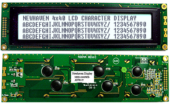
Newhaven 4×40 LCD (Source: http://www.newhavendisplay.com)
So how to support that display with the LCDHTA Processor Expert component and driver?
Display Connection
Looking at the data sheet, there was something interesting about it: the display has not a single ‘E’ signal, it has two: E1 and E2!

NHD-0440WH Pins (Source: NHD-0440WH Datasheet)
So the E1 and E2 are used to switch between the upper and lower lines.
Memory Map
The display memory map is interesting too for the 4 lines:

NHD-0440WH Memory Map (Source: NHD-0440WH Datasheet)
So the line 1 and 3 share the same memory addresses? That’s strange. So how to write a driver for it?
2 Displays in One!
Until I realized: they have put 2 display controller together! This display is not really a 4×40 character display, it is two 2×40 displays in a single display packaging :-). This is the same as if I would combine two displays on the same bus like this:

Two Displays form a 4 Line Display
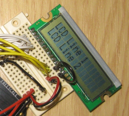
Emulating the 4×40 Display
As I did not had the Newhaven 4×40 display available to verify the driver, I wired two 2×16 displays together. And with this, I was able to build a 4×16 (potentially 4×64) character display:
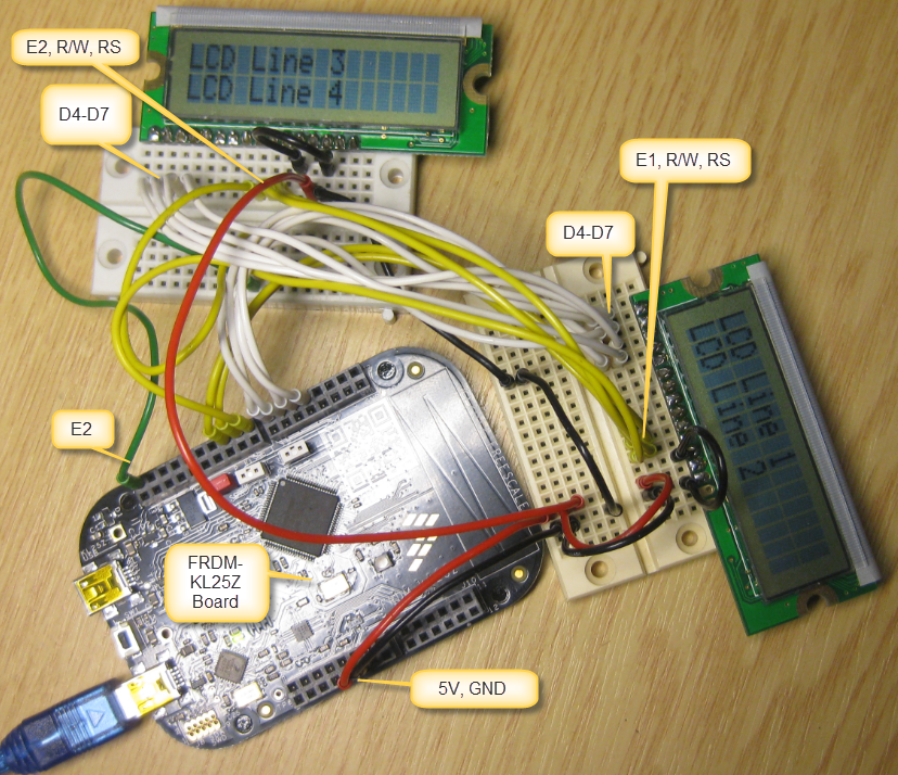
Emulating Newhaven 4×40 Display
LCDHTA Processor Expert Component
The LCDHTA Processor Expert component supports now this ‘dual’ display mode too. For this, there is now an optional E2 signal in the properties:

E2 Signal in LCDHTA Component
Two switch between the two controllers, the new method UseDisplay() is available:

UseDisplay Method
With it, I can switch between the two displays:
LCD1_UseDisplay(1);  /* switch to upper/first display */
LCD1_Clear();
LCD1_WriteLineStr(1, "LCD Line 1");
LCD1_WriteLineStr(2, "LCD Line 2");

LCD1_UseDisplay(2);  /* switch to second display */
LCD1_Clear();
LCD1_WriteLineStr(1, "LCD Line 3");
LCD1_WriteLineStr(2, "LCD Line 4");
Potentially, it would be possible to add even more displays/lines. But that’s something until I really need it 😉
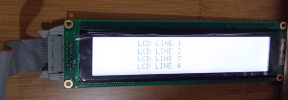
4×40 LCD in Action
Below are pictures of the Newhaven 4×40 LCD in action:

Notebook with Tower Module and LCD (Source: Daniela Solorzano)

Top View with LCD and Tower (Source: Daniela Solorzano)
Following code
LCD1_UseDisplay(1);
LCD1_GotoXY(1,10);
LCD1_WriteString("LCD LINE 1");
LCD1_GotoXY(2,10);
LCD1_WriteString("LCD LINE 2");
LCD1_UseDisplay(2);
LCD1_GotoXY(1,10);
LCD1_WriteString("LCD LINE 3");
LCD1_GotoXY(2,10);
LCD1_WriteString("LCD LINE 4");
generates this:

Newhaven 4×40 LCD Output (Source: Daniela Solorzano)
LCD1_UseDisplay(1);
LCD1_Write('1');
LCD1_UseDisplay(2);
LCD1_Write('3');

Write Test (Source: Daniela Solorzano)
LCD1_UseDisplay(1);
LCD1_WriteLn();
LCD1_Write('2');
LCD1_UseDisplay(2);
LCD1_WriteLn();
LCD1_Write('4');

WriteLn Test (Source: Daniela Solorzano)
LCD1_ShiftRight();
LCD1_UseDisplay(1);
LCD1_Write('1');
LCD1_ShiftRight();
LCD1_UseDisplay(2);
LCD1_Write('2');

Shift Right Test (Source: Daniela Solorzano)
LCD1_ShiftLeft();
LCD1_UseDisplay(1);
LCD1_Write('1');
LCD1_ShiftLeft();
LCD1_UseDisplay(2);
LCD1_Write('2');

Shift Left Test (Source: Daniela Solorzano)
LCD1_UseDisplay(1);
LCD1_GotoXY(1,10);
LCD1_CursorOn();

Cursor Test (Source: Daniela Solorzano)
LCD1_UseDisplay(1);
LCD1_GotoXY(1,10);
LCD1_BlinkingOn();

Blinking Cursor Test (Source: Daniela Solorzano)
Summary
The Hitachi HD44780 is very common and can be considered as ‘industry standard’. But as with any standards, it comes with limitations, and standards sometimes make it hard to move the technology to the next level. And sometimes it causes kind of strange solutions as creating a 4 line display with two display controllers on it. Switching the Ex lines I can now support up to for 4 lines and up to 64 characters for each line. And if needed, I can extend that concept for more lines/displays.
Happy Displaying 🙂

It works as a charm! Thank you for saving a lot of time! Just one thing, how can I read some LCD data? I see the option to enable this in the PE component but I’m not able to find any Read method.
LikeLike
It is not about reading data, but reading a bit/pin from the module to know if it is ready or not. Otherwise the driver needs to poll/wait.
LikeLike
Pingback: Tutorial: HD44780 Display Driver with NXP MCUXpresso SDK | MCU on Eclipse