Question: What makes 8 times ‘beep’, but I cannot hear it?
Answer: My ultrasonic range finder 🙂

FRDM-KL25Z with HC-SR04
What I have added to my FRDM-KL25Z board is an ultrasonic distance sensor, measuring distances up to 4 meters.
HC-SR04 Ultrasonic Sensor
The HC-SR04 sensor is a 4 pin sensor, at an incredible price point. I have mine from Play-Zone, but I have seen offers in the internet for around $6 too.
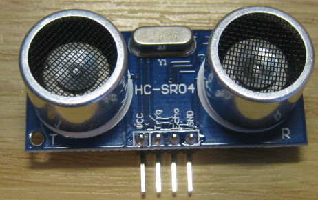
HC-SR04 Front Side
The backside features all the electronics to which simply usage of the sensor:
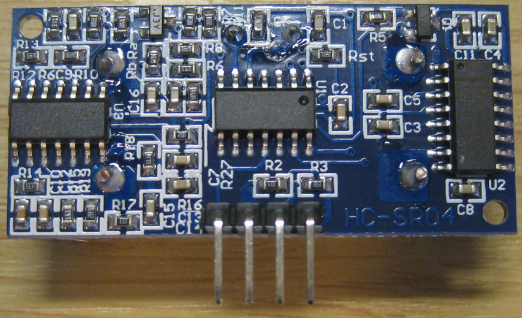
HC-SR04 Back Side
With simple I mean, it only needs 4 pins:
- Vcc (+5V DC supply)
- Trig (TTL input, to trigger a measurement)
- Echo (TTL output, pulse proportional to distance)
- GND (ground)
Note: There is a similar module on the market: the Parallax Ping))) or Seedstudio one which only use 3 pins (Vcc, Trig+Echo, GND). While this saves a pin, it makes usage a big more complicated as I would have to switch between output and input on a single pin. So I prefer the 4 pin variant.
Using the sensor is simple:
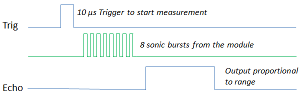
HC-SR04 Timing Diagram
- Send a 10 us pulse on Trig
- In reaction to this, the sensor will send 8 sonic bursts to measure the distance
- After sending the burst, the sensor will raise the Echo signal until it receives the echo back. That means the length of the Echo signal corresponds to time the burst was travelling forward and echoed back.
Below is a snapshot with a logic analyzer:
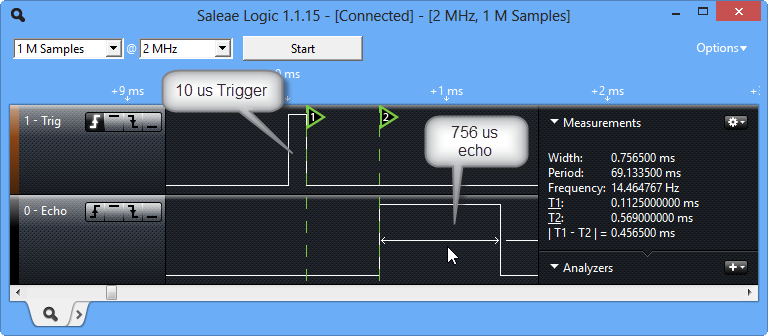
HC-SR04 Timing
After the 10 us Trigger signal, the sensor sends the burst during ‘1’ and ‘2’ (around 456 us), followed by the Echo signal duration of 756 us. The 756 us corresponds to the time it took for the burst to come back.
The speed of sound is about 340 m per second (depends on temperature and air relative humidity). A good approximation is 29 us per cm (or 58 us per centimeter as it is for back and forward). With the above example, the 756 us would result in 756/29/2 = 13 cm distance.
💡 For decimal system challenged engineers: instead of a divider of 58, use a divider of 148 to get the result in inch instead of centimeter.
Hardware Connection
I’m using a breadboard for easy wiring and connection.
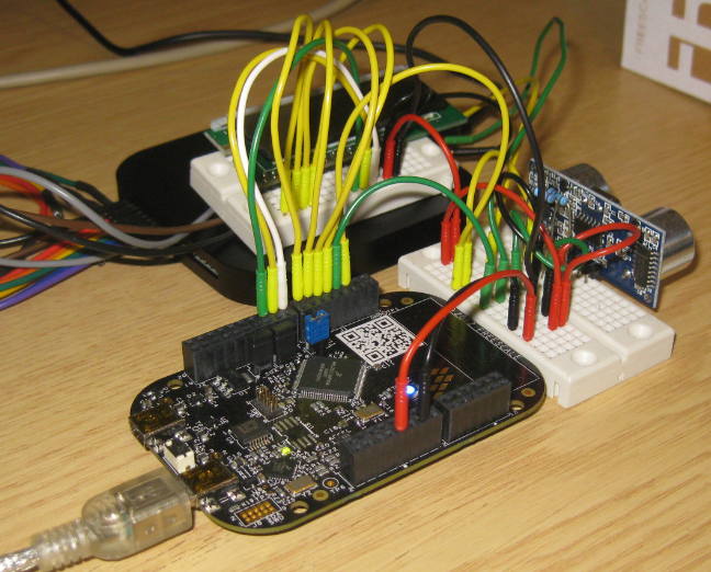
Breadboard Wiring with Freedom Board, Sensor, LCD and Logic analyzer
To visualize the measurement, I’m using the 2×16 Character display I have used in my earlier post. Of course a LCD is optional. I used the same wiring as before:
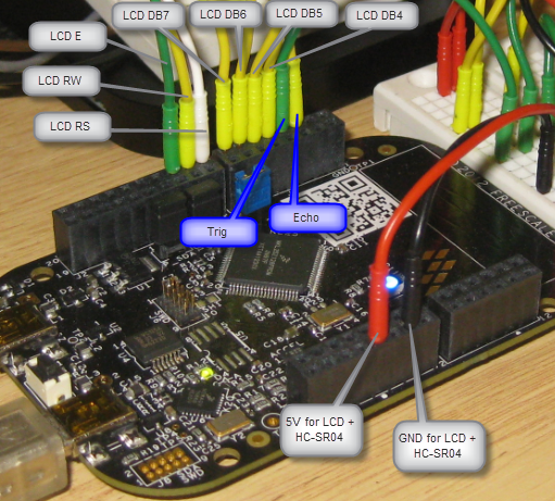
Signals with Labels
=================================================================
 SIGNAL LIST
-----------------------------------------------------------------
SIGNAL-NAME [DIR]        => PIN-NAME [PIN-NUMBER]
-----------------------------------------------------------------
DB4_D4 [I/O]             => TSI0_CH5/PTA4/I2C1_SDA/TPM0_CH1/NMI_b [30]
DB5_D5 [I/O]             => PTA5/USB_CLKIN/TPM0_CH2 [31]
DB6_D6 [I/O]             => CMP0_IN2/PTC8/I2C0_SCL/TPM0_CH4 [65]
DB7_D7 [I/O]             => CMP0_IN3/PTC9/I2C0_SDA/TPM0_CH5 [66]
E_D10 [Output]           => PTD0/SPI0_PCS0/TPM0_CH0 [73]
LED_BLUE [Output]        => ADC0_SE5b/PTD1/SPI0_SCK/TPM0_CH1 [74]
LED_GREEN [Output]       => TSI0_CH12/PTB19/TPM2_CH1 [54]
LED_RED [Output]         => TSI0_CH11/PTB18/TPM2_CH0 [53]
RS_D8 [Output]           => PTA13/TPM1_CH1 [33]
RW_D9 [Output]           => ADC0_SE6b/PTD5/SPI1_SCK/UART2_TX/TPM0_CH5 [78]
US_Echo_D2 [Input]       => PTD4/LLWU_P14/SPI1_PCS0/UART2_RX/TPM0_CH4 [77]
US_Trig_D3 [Output]      => PTA12/TPM1_CH0 [32]
=================================================================
What I need is the supply voltage, ground, an output pin (Trig) and an input pin to measure the signal (Echo).
The HC-SR04 uses TTL (5V) supply voltage and logic levels. The FRDM-KL25Z processor is a 3.3V one, but the board provides 5V on the header. The HC-SR04 can use 3.3V levels on the Trig signal, but provides a 5V signal on the Echo pin. To get the signal to the 3.3V level, I use a simple voltage divider with a 27k Ohm and 15k Ohm resistor:

Voltage Divider with two resistors
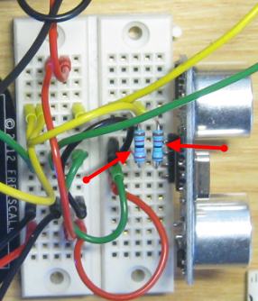
Voltage Divider Detail
CodeWarrior Project
With the wizard (File > New Bareboard Project) I create a new project for the KL25Z and Processor Expert. I need two things:
- Create a 10 us pulse on the Trig (Trigger) pin
- Measure the echo on the Echo pin
Trigger
For the Trigger pin I add a BitIO_LDD component to my project:
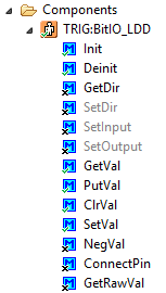
BitIO_LDD Component
I configure it as Output pin on PTA12:

Trigger Properties
Additionally I add the Wait component to the project:
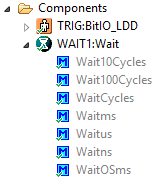
Wait Component
Generating the 10 us pulse now is trivial:
TRIG_SetVal(trigDevice); WAIT1_Waitus(10); TRIG_ClrVal(trigDevice);Wait! There is some more infrastructure needed, such as this trigDevice handle. More on this below.
Echo Pulse Measurement
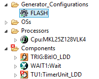
To measure the echo, I add a TimerUnit_LDD component:
TimerUnit_LDD added
That component shows errors for now, because I need to configure it for my needs. What I want is a timer measuring the echo signal. For this I need to set up a timer which starts counting on the echo raising edge, and stops at the falling edge. For this I need a timer channel.
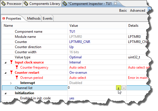
I add a new channel using the ‘+’ icon:
Adding Timer Unit Channel
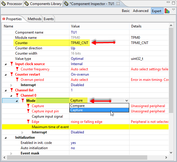
For this I’m selecting the TPM0_CNT as counter and configure the channel for ‘capture’:
💡 You will understand later on why I have selected this particular counter.
Using TPM0_CNT and Capture Mode
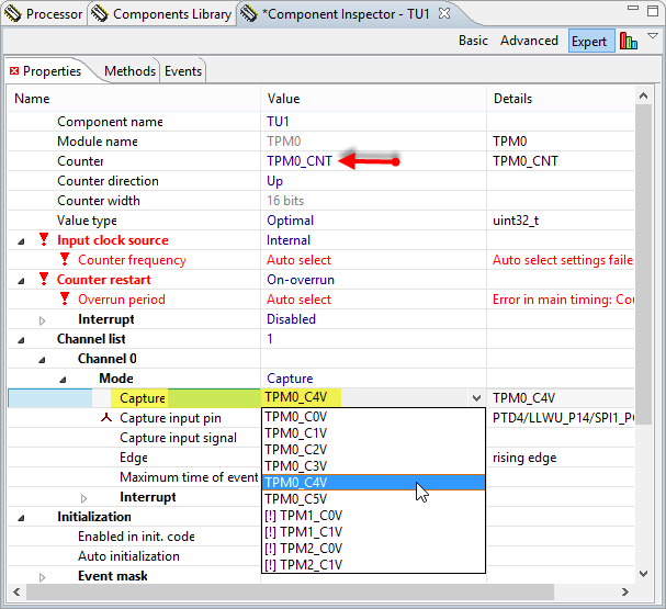
As I have connected the Echo signal on PTD4, I need to use that pin as ‘Capture input pin’:
PTD4 as input capture pin
As hinted by the pin name (PTD4/LLWU_P14/SPI1_PCS0/UART2_RX/TPM0_CH4), this pin is available on TPM0_CH4, so I need to configure this as capture device:
selected capture device
💡 Now you see why I have selected TPM0_CNT above as Counter device. I admit: that’s not something easy to know about, because this KL25Z has mirades of pin and mapping configuration (called Pin Muxing) :-(. One way is to guess what is behind from the pin names (this is what I try first). Otherwise you need to read through the device reference manual (which is very time-consuming). I wish these devices would be much less complicated and easier to use….
I want to get an interrupt for both the raising edge and falling edge of the Echo signal: I enable interrupts and configure it for both edges. And I give the signal a nice name:
Interrupt Settings
That’s not enough: I need to enable interrupts for the counter too:
Enabled Interrupts for Counter
Counter Frequency
I still have errors showing up for my Timer/Counter: I need to configure the counter frequency: This is the clock which is used for my counter. In principle: the higher the frequency, the more precise the measurement will be. As always: a good balance is required. First, I configure the counter frequency:
Configuring the counter frequency
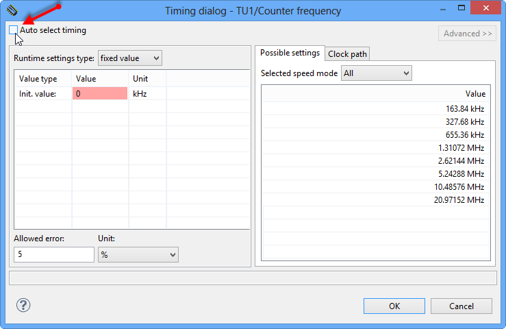
The first thing to do is to disable ‘Auto select timing’:
Disabling Auto Select timing
💡 Processor Expert usually chooses good default values, but fails (for whatever reason?) to do this properly for timers on the ARM platform. So as solution I always disable auto-select-timing and explicitly make my choice. Maybe better that way anyway 🙂
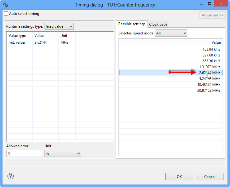
I make a gut guess and select a 2.x MHz clock from the list (double-click to assign it):
Selected clock frequency
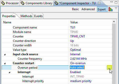
Counter Overrun
There one thing to consider: when will the counter overflow? I keep in mind that with the speed of sound, around 4 meters distance means 400*58us makes 23.5 ms Echo signal pulse. So I need to make sure that for this distance, my counter does *not* overflow. I can check this in the ‘Overrun period’ settings:
Overrun period
Deselecting ‘auto select timing’ again will show the overrun period time:
Overrun period
So my timer will overrun after 25 ms, so I’m fine 🙂
Next, I need to enable two methods I want to use. I need to read the counter value, and I need to reset it. As such, I enable the two methods (right-click on the method name and select ‘Toggle Enable/Disable’):
Enabled TimerUnit_LDD Methods
I notice the two events called:


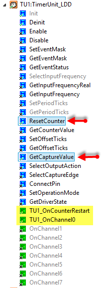
- OnCounterRestart() is called when there is a restart/overflow of the counter
- OnChannel() is called for every interrupt of my channel. Remember that I have it configured for creating an interrupt/event for both raising and falling edge.
State Machine
I’m using a state machine to go through the different measurement phases:
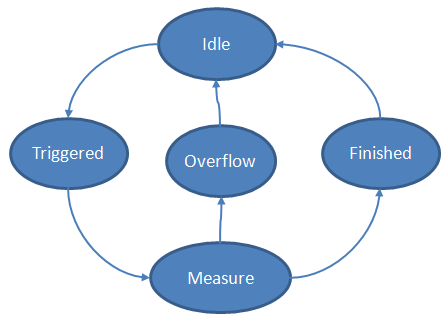
State Diagram
- Idle: Sensor is idle
- Triggered: we sent the trigger signal to the sensor
- Measure: we received raising edge of echo signal and are measuring
- Overflow: Counter overflow happened (see above)
- Finished: received falling echo signal edge and we have captured the echo signal time
Another way is to show the different states on the timing diagram (without the Overflow case):
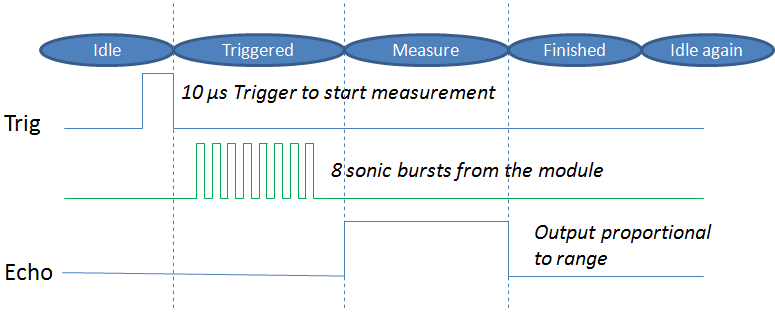
Timing and State Diagram
With this in mind, the implementation is pretty straight forward. First, an enumeration for the state machine states:
typedef enum { ECHO_IDLE, /* device not used */ ECHO_TRIGGERED, /* started trigger pulse */ ECHO_MEASURE, /* measuring echo pulse */ ECHO_OVERFLOW, /* measurement took too long */ ECHO_FINISHED /* measurement finished */ } US_EchoState;Next the data structure to keep all my data:
typedef struct { LDD_TDeviceData *trigDevice; /* device handle for the Trigger pin */ LDD_TDeviceData *echoDevice; /* input capture device handle (echo pin) */ volatile US_EchoState state; /* state */ TU1_TValueType capture; /* input capture value */ } US_DeviceType; static US_DeviceType usDevice; /* device handle for the ultrasonic device */And here is how it gets initialized:
void US_Init(void) { usDevice.state = ECHO_IDLE; usDevice.capture = 0; usDevice.trigDevice = TRIG_Init(NULL); usDevice.echoDevice = TU1_Init(&usDevice); }Event Handlers
Notice the call to
TU1_Init()where I pass a pointer to my data structure: That way I get a nice handle passed from the Processor Expert event routines (in events.c) I can use for my own routines.
Remember that I get interrupts for raising and falling edge, and for overflow.
I handle that in Events.c:/* ** =================================================================== ** Event : TU1_OnChannel0 (module Events) ** ** Component : TU1 [TimerUnit_LDD] ** Description : ** Called if compare register match the counter registers or ** capture register has a new content. OnChannel0 event and ** Timer unit must be enabled. See and ** methods. This event is available only if a ** is enabled. ** Parameters : ** NAME - DESCRIPTION ** * UserDataPtr - Pointer to the user or ** RTOS specific data. The pointer passed as ** the parameter of Init method. ** Returns : Nothing ** =================================================================== */ void TU1_OnChannel0(LDD_TUserData *UserDataPtr) { US_EventEchoCapture(UserDataPtr); } /* ** =================================================================== ** Event : TU1_OnCounterRestart (module Events) ** ** Component : TU1 [TimerUnit_LDD] ** Description : ** Called if counter overflow/underflow or counter is ** reinitialized by modulo or compare register matching. ** OnCounterRestart event and Timer unit must be enabled. See ** and methods. This event is ** available only if a is enabled. ** Parameters : ** NAME - DESCRIPTION ** * UserDataPtr - Pointer to the user or ** RTOS specific data. The pointer passed as ** the parameter of Init method. ** Returns : Nothing ** =================================================================== */ void TU1_OnCounterRestart(LDD_TUserData *UserDataPtr) { US_EventEchoOverflow(UserDataPtr); }In case of Overflow I simply set the state machine to the overflow state:
void US_EventEchoOverflow(LDD_TUserData *UserDataPtr) { US_DeviceType *ptr = (US_DeviceType*)UserDataPtr; ptr->state = ECHO_OVERFLOW; }While in the interrupt/event for raising or falling edge, I reset the counter value at raising edge, or read out the counter value at falling edge:
US_DeviceType *ptr = (US_DeviceType*)UserDataPtr; if (ptr->state==ECHO_TRIGGERED) { /* 1st edge, this is the raising edge, start measurement */ TU1_ResetCounter(ptr->echoDevice); ptr->state = ECHO_MEASURE; } else if (ptr->state==ECHO_MEASURE) { /* 2nd edge, this is the falling edge: use measurement */ (void)TU1_GetCaptureValue(ptr->echoDevice, 0, &ptr->capture); ptr->state = ECHO_FINISHED; }With this I reset the counter on the raising edge, and get the counter value at the falling edge. Then I set the state to ‘finished’: this will be the state I wait for (polling) we will see later.
Measure!
I have implemented a function which sends the trigger, and then waits until the measurement has been finished:
uint16_t US_Measure_us(void) { uint16_t us; /* send 10us pulse on TRIG line. */ TRIG_SetVal(usDevice.trigDevice); WAIT1_Waitus(10); usDevice.state = ECHO_TRIGGERED; TRIG_ClrVal(usDevice.trigDevice); while(usDevice.state!=ECHO_FINISHED) { /* measure echo pulse */ if (usDevice.state==ECHO_OVERFLOW) { /* measurement took too long? */ usDevice.state = ECHO_IDLE; return 0; /* no echo, error case */ } } us = (usDevice.capture*1000UL)/(TU1_CNT_INP_FREQ_U_0/1000); return us; }It sends the 10 us trigger and then waits for the finished state. In case of overflow (no echo received), I simply return a value of zero.
The function returns the measured echo time in microseconds. To deal with different timer frequencies, the macro
TU1_CNT_INP_FREQ_U_0is used which is generated by Processor Expert.Calculating to Distance
Usually I’m not interested in the echo time, but rather in the distance itself. For this I have created a utility function to transform the echo time (microsecond) into centimeter distance:
static uint16_t calcAirspeed_dms(uint8_t temperatureCelsius) { /* Return the airspeed depending on the temperature, in deci-meter per second */ unsigned int airspeed; /* decimeters per second */ airspeed = 3313 + (6 * temperatureCelsius); /* dry air, 0% humidity, see http://en.wikipedia.org/wiki/Speed_of_sound */ airspeed -= (airspeed/100)*15; /* factor in ~15% for a relative humidity of ~40% */ return airspeed; } uint16_t US_usToCentimeters(uint16_t microseconds, uint8_t temperatureCelsius) { return (microseconds*100UL)/calcAirspeed_dms(temperatureCelsius)/2; /* 2 because of two way */ }💡 Speed of sound depends on factors like temperature, relative humidity and above sea level (media density). The above function is not counting in everything, but is accurate enough for me.
Example Application
Now using it is pretty simple: from my main routine I intialize my drivers, and then periodically call the function to measure the distance. To make things visual, I show values on a LCD plus show with the RGB LED the distance:
static void Measure(void) { uint16_t us, cm; uint8_t buf[8]; us = US_Measure_us(); UTIL1_Num16uToStrFormatted(buf, sizeof(buf), us, ' ', 5); LCD1_GotoXY(1,5); LCD1_WriteString((char*)buf); cm = US_usToCentimeters(us, 22); UTIL1_Num16uToStrFormatted(buf, sizeof(buf), cm, ' ', 5); LCD1_GotoXY(2,5); LCD1_WriteString((char*)buf); LEDR_Put(cm<10); /* red LED if object closer than 10 cm */ LEDB_Put(cm>=10&&cm<=100); /* blue LED if object is in 10..100 cm range */ LEDG_Put(cm>100); /* blue LED if object is in 10..100 cm range */ } /*lint -save -e970 Disable MISRA rule (6.3) checking. */ int main(void) /*lint -restore Enable MISRA rule (6.3) checking. */ { /* Write your local variable definition here */ /*** Processor Expert internal initialization. DON'T REMOVE THIS CODE!!! ***/ PE_low_level_init(); /*** End of Processor Expert internal initialization. ***/ /* Write your code here */ US_Init(); LCD1_Clear(); LCD1_WriteLineStr(1, "us: "); LCD1_WriteLineStr(2, "cm: "); for(;;) { Measure(); WAIT1_Waitms(50); /* wait at least for 50 ms until the next measurement to avoid echos */ } /*** Don't write any code pass this line, or it will be deleted during code generation. ***/ /*** RTOS startup code. Macro PEX_RTOS_START is defined by the RTOS component. DON'T MODIFY THIS CODE!!! ***/ #ifdef PEX_RTOS_START PEX_RTOS_START(); /* Startup of the selected RTOS. Macro is defined by the RTOS component. */ #endif /*** End of RTOS startup code. ***/ /*** Processor Expert end of main routine. DON'T MODIFY THIS CODE!!! ***/ for(;;){} /*** Processor Expert end of main routine. DON'T WRITE CODE BELOW!!! ***/ } /*** End of main routine. DO NOT MODIFY THIS TEXT!!! ***/💡 If you do not have a LCD, simply strip off the LCD code :-).
The other thing to consider: inside the
main()loop I use a delay of 50 ms: In case of an echo it will take about 25 ms for the echo to arrive: with 50 ms I will be calm for some time until I send another ‘ping’.And here is a short video to see everything in action:
Summary
Once getting through the concept and principles, it is rather easy to use an ultrasonic range sensor like the HC-SR04. Setting up the input capture/counter is the most tricky part. But I think with the concepts and steps outlined above, this should work out pretty good for any other microcontroller, especially if used with CodeWarrior and Processor Expert.
The project shown above is available here.
If you are looking for improvements, here are some ideas:
- properly calculate in the humidity and air density.
- Using a temperature sensor to factor in the current air temperature.
- Averaging the samples.
- Dynamic measurement time, adaptive to the distance found to save battery energy.
- Using an RTOS like FreeRTOS. Especially to reduce the ‘busy waiting’ time and to do something useful during that time.
- Shell support (e.g. FSShell) to show values on a console, including setting of calibration values.
- Create a Processor Expert Component for it.
- As the ultrasonic beam is rather focused: add a pan a tilt servo to it to ‘explore’ more.
- Adding more sensors and actuators to use it for a robot application 🙂
Happy Ultrasonic-Sounding 🙂

Hi, Erich!
Great job!, I really enjoy your posts!
I’m having some troubles adapting an example of an USB HOST MSD example to work with PE, I posted the problem in the Freescale Forums:
freescale community thread/303017
Can you give some orientation?
Thanks in advance 🙂
LikeLike
Hi Alex,
sorry, I do not have that K20, so I’m not of any help here I think.
LikeLike
I tried the same in my Freedom board and failed 😥 , It would be great for you to do a tutorial on this, when you can, no pressure 🙂
LikeLike
Hi Alex,
well, I thought that this *is* already a tutorial? Maybe one of your settings is wrong? Could you try the project (link at the end of the tutorial). You might simply remove the LCD code, and if you use the same pins, then it should work for you as well.
Hope this helps,
Erich
LikeLike
Upps!! Sorry for the confusion, I meant to read a USB stick with the Freedom board.
LikeLike
Hi Erich,
Thanks for the above. It may save someone’s life some day (remote chance). I have been pondering how to impliment an emergency stop circuit on a device I have been designing with the FRDM board.
I think using the above idea to detect if someone (or part of someone) is in a dangerous place is a good idea.
Thank you.
LikeLike
You are welcome. Just keep in mind that the ultrasonic beam is rather small and focused. To cover a larger area it is necessary to move the beam around, or to use multiple sensors. Depending on your application: in robotics (I mean big industrial robots) they are using in many cases a ‘laser curtain’: multiple laser beams to form a curtain to detect if something/someone is moving into the danger zone. That’s simpler and more reliable than ultrasonic in my view.
LikeLike
Pingback: The Freedom Robot | MCU on Eclipse
Hi,
After reading your posts I ordered one FRDM-KL25Z and started to have fun:)
Can you please help me with this application:
First of all the compiled code provided is not loading properly. (No LCD attached but the RGB indication should have worked)
Downloaded the project.
Removed the LCD component.
Recompiled the code.
After recompiling and loading the RED led stays always on.
Added ConsoleIO component and printf(“time is:%u\n”, us); after us = US_Measure_us(); so I can read the values on my PC.
Now the I can see that us has some values as I move an object in front of the sensor but they are like:27, 24, 21,18,15,12, 9 and only at very close range(5 cm). If the object is farther away then the us value displayed is always 12.
Some representation problem? Missing some bits from the uint16_t?
Thank you.
Cristian
LikeLike
Hi Cristian,
Could you verify that your sensor is returning the correct pulse on the echo line? Best if you could use a logic analyzer or oszilloscope.
Erich
LikeLike
Hi,
thank you for the quick answer,
-No logic analyzer, maybe will borrow a scope.
-Will check the setup again tomorrow
-When trying to load the precompiled code provided by you (Freedom_HC-SR04.hex) the green led near the pemicro chip acts strangely (series of 7 or 8 rapid blinks, pause, then blinks again). Something is wrong with that code?
-I am not mistreating that bird, that baby entered my house and just before relieving it I took a snapshot 🙂 They are little owls.The whole family lives right under my roof.
Something like this:
http://www.beleefdelente.nl/vogel/steenuil
LikeLike
Nice birds, indeed!
I suggest that you check as well the wiring:Make sure you have that voltage divider in place, plus everything connected to the right pins on the Freedom board.
And it could be possible as well that your ultrasonic module is not working properly. I assume you are using the HC-SR04? Because there might be different types of modules around.
LikeLike
Hi!
Problem Solved!
The HC-SR04 module was defective! Replaced it and now the application works nicely 🙂
Maybe some people are used to it, but I discovered today: The PicKit2 programmer has a Logic Tool function which is very useful.
Still 2 problems remain:
1-The code provided by you Erich has the Flash image format set as “ihex” and I cannot load it into the FRDM-KL25Z. I have to set it as “srec” and rebuild the project. Also the LCD component has to be removed if LCD module not available.
2-Measuring the Trig signal I noticed it is 120us long, not 10us as expected. Trying to decrease the argument of the WAIT1_Waitus(10); function I can only obtain 3 us for WAIT1_Waitus(5) and no other values in between. Why could this happen?
Keep up the good work!
Cristian
LikeLike
Hi Cristian,
good to hear you are making progress.
About 1): Thanks, I have fixed this now on https://github.com/ErichStyger/mcuoneclipse/tree/master/Examples
About 2): Are you sampling with a high enough frequency in your logic analyzer. I mean it should be at least in the 1 us range if not faster.
And are you using the latest version of ‘Wait’ component? I had fixed some timing back in December (http://steinerberg.com/EmbeddedComponents/Wait/home.htm). Wait is using ‘busy waiting’ and not very precise, and it can be interrupted by other interrupts. So you might disable interrupts around the Wait() call.
LikeLike
Hi, do you have any project in which you read analogic signal (outside of the board) and display it at LCD?
LikeLike
Hello, no, not at this moment.
LikeLike
I can use this sensor in PIC18F4550?
LikeLike
Hi John, yes, I do not see why this should be a problem. All what you need is an output pin plus an input pin. And of course adopt the driver/software for the PIC.
LikeLike
I’m now learning PIC am newbie. I know very little about PIC
I have a project, and I have to measure the distance from this sensor (HC-SR04) using PIC18F4550.
Do you know any tutorial to learn how to do?
LikeLike
Hi John,
I did an internet search for “HC-SR04 PIC” and received plenty of hits/pages. I suggest to start there?
LikeLike
I found this: http://www.youtube.com/watch?v=dRq0e9rwqHo
but does not use the program that work, work with MPLAB.
Do you know any tutorial for this program?
LikeLike
Hi John,
no, I do not have a tutorial for MPLAB, sorry.
LikeLike
Pingback: Tracked Robot Update: Ultrasonic, Line Sensor and Shell with SMAC 802.15.4 | MCU on Eclipse
Pingback: Mini Sumo Robot with Proximity Sensors | MCU on Eclipse
Hello,
First, sorry my english.
My name is Fernando, I from Brazil. Congratulation foi job.
I wonder if it is possible to add an additional ultrasonic sensor using the same component TimerUnit_LDD. And how do I?
Thank you
LikeLike
Hi Fernando,
thanks 🙂
no worries about English: mine is not perfect too 😉
I think it should be possible to add another sensor, but I have not done this. Would need to try first myself. Sure the same time base could be used to measure the signal.
LikeLike
Thank you for the reply!
This, put two sensors, however, he only reads a sensor, the other gives error in this part:
while (usDevice.state! = ECHO_FINISHED) {
if (usDevice.state == ECHO_OVERFLOW) {
usDevice.state = ECHO_IDLE;
return 0; / * ERROR * /
}
}
The second sensor enters if and returns 0. I had to declare another variable of type “static US_DeviceType” you know if you need to set something before you start using?
LikeLike
Or a sensor picks up the same distance from each other!
LikeLike
It could be much better if you expand the tutorial in order to build more complex robotics applications. A series of tutorial can be found in this article http://www.intorobotics.com/interfacing-programming-ultrasonic-sensors-tutorials-resources/
LikeLike
Yes, agreed. This tutorial is just a starting point. On GitHub I have placed some more advanced usage examples, see https://mcuoneclipse.com/2013/09/08/mini-sumo-robot-with-proximity-sensors/
BTW: Nice summary you wrote about different ultrasonic modules, thanks for this!
LikeLike
Hi Erich,
Great tutorial- been really helpful so far! I am new to programming and have a couple of questions.
With the code, what header file should be used?
Should the code you have given on this page be in one .c source file or a different file for each section?
Thank you for your help
Jonny
LikeLike
Hi Jonny,
best if you check out the sources here:
https://github.com/ErichStyger/mcuoneclipse/tree/master/Examples
LikeLike
Spot on, thank you!
The only problem I’m having is that some of the headers have errors (unresolved inclusions?). These are the following:
#include “LEDR.h”
#include “LEDpin1.h”
#include “BitIoLdd1.h”
#include “LEDG.h”
#include “LEDpin2.h”
#include “BitIoLdd2.h”
#include “LEDB.h”
#include “LEDpin3.h”
#include “BitIoLdd3.h”
#include “TU1.h”
#include “LCD1.h”
#include “RW1.h”
#include “BitIoLdd15.h”
#include “EN1.h”
#include “BitIoLdd4.h”
#include “RS1.h”
#include “BitIoLdd5.h”
#include “DB41.h”
#include “BitIoLdd10.h”
#include “DB51.h”
#include “BitIoLdd11.h”
#include “DB61.h”
#include “BitIoLdd12.h”
#include “DB71.h”
#include “BitIoLdd13.h”
#include “UTIL1.h”
Do you know what the problem might be with this? Do I need to install a library somewhere?
Thanks
Jonny
LikeLike
Yes, you need to load additional Processor Expert libraries/components (see https://mcuoneclipse.com/2013/05/09/processor-expert-component-peupd-files-on-github/) and generate code.
LikeLike
Once loaded do I need to add each component into the project? Many of them have errors- will these need setting for the specific pins etc on the board? Thanks
LikeLike
Hi Jonny,
The components are already added to the project. If you have all components installed, you can simply generate code and everything should work out of the box. Of xourse if you have the sensor on different pins, then you need to change the pin settings. Maybe you are not (yet?) familiar with Processor Expert and how this works? I suggest to have a look at this tutorial (https://mcuoneclipse.com/2012/09/07/tutorial-enlighting-the-freedom-kl25z-board/) as it goes through the individual steps.
LikeLike
Erich,
First off, thank you so much for all your tutorials. I’ve been playing with the Kinetis boards for some hobby projects over the last year and your tutorials and insights have been invaluable.
I’ve modified your code to use 4 sensors. I added three additional channels to the timer unit. I also added function pointers for the trigger pin functions to your US_DeviceType struct and then created another struct (US_Devices) that holds an array of 4 US_DeviceType structs and a counter. In the init function I set the function pointers for each sensor to the appropriate pin function. Then I modified your code to loop through the 4 sensors updating the counter in the struct using the counter and pin function pointers in the struct pointer passed to the events. Theoretically it should be usable for any number of sensors.
I’ve posted it to GitHub so others can use it if they like.
https://github.com/madseumas/Kinetis/tree/master/Ultrasonic
It has some other code from FreeRTOS; I keep the US sensors in their own task since US_Measure blocks and I send off the results to another task via a queue.
At some point I’d like to get it so I can fire the sensors in pairs (front/back and left/right) at the same time, but since the timer unit’s overflow event fires for all 4 channels without indicating which channel overflowed I’m not sure yet how to go about that.
I’m a relative C newb so I wouldn’t be surprised if there are any bugs I haven’t caught yet.
Once again thank you so much for all of your tutorials!
LikeLike
Hi,
many thanks for sharing your work. I plan to build a dual-sensor system in the near future, so this for sure would be helpful. Many thanks again!
LikeLike
Thank you for your blog, it’s very helpful.
I made robot on FRDM-KL05Z with HC-SR04 too.
http://www.robotmaker.ru/2014/03/22/1366/
LikeLike
thanks for sharing, that one really looks very nice!
LikeLike
Hi Erich,
Thank for your great work. I have some troubles with load your ready code to CodeWarrior and programm to board.
Can you tell how can I do it properly ?
(sorry for that simple issue but I’m a newbie ;P)
Best regards
LikeLike
Hi Bartek,
are you using the FRDM-KL25Z board? Keep in mind that the board comes with a bootloader shipped (and not with the debug application). So you need to load the right firmware. I recommend that you use the latest P&E one (see https://mcuoneclipse.com/2013/12/14/new-pe-opensda-firmware-v114/).
See https://mcuoneclipse.com/2012/09/20/opensda-on-the-freedom-kl25z-board/ how to program the new firmware.
LikeLike
Hi,
yes I use FRDM-KL25Z. I did like this: enter the bootloader mode, than I droped this file “MSD-DEBUG-FRDM-KL25Z_Pemicro_v114.SDA” to root and replug the board.
LikeLike
Yes, that sounds ok. What operating system are you using? Windows 8.1? If so, then there is a known problem: https://mcuoneclipse.com/2013/10/12/frdm-board-bootloader-fails-with-windows-8-1-preview/
That problem is solved with the V1.14 firmware (but you need a Windows 7 machine (or 8.0)) to update the bootloader firmware.
LikeLike
I use Windows 7 (home premium version x64).
LikeLike
Then this should not be an issue. Can you copy the file with the DOS shell/command prompt?
And if you have a virus scanner, to disable it?
LikeLike
All this stuff was done earlier (open sda update). Thing is that my board is working fine (I can run the .srec precompiled program and it works). The point is I want to load ultra sonic project on board properly. I use “flash programmer” –> “flash file to target”, I choose .hex file (“file to flash”) from your project and press “erase and program”. It shows that transfer is succesful but after replug nothing is happend (rgb diode is dead). All devices are connect properly.
LikeLike
Ok I did it ! I load .elf file instead .hex and it’s work 😀
Thank for your help
Best regards !
LikeLike
Try with an S19 file (Motorola S19 file). .Hex are usually intel hex files, and I think this is not supported by the bootloader.
LikeLike
Pingback: Programmable Ultrasonic Sensor Shield for FRDM Board | MCU on Eclipse
Pingback: Sensor and Communication Shield for Sumo Robot | MCU on Eclipse
Hi Erich,
Thank for your great work. But I am new at this and I would like know how can I create a simple timer using external interrupt.
Thank you.
LikeLike
Welcome to a new world 🙂 Not sure what you mean with ‘using an external interrupt’? I have a tutorial related to timers for example here: https://mcuoneclipse.com/2012/08/13/tutorial-timer-led-with-processor-expert-for-kinetis/
LikeLike
Hi Erick, thank you for your blog, it’s very helpful.
I have a question regarding the timer channels. My application needs 2 timers. I tried to add one more channel in the processor expert. However, I don’t know how to build the code with two or more channels. Could you help me?
Thank you so much.
LikeLike
Hi Michael,
You can have multiple timers with each having a number of channels. You can use the TimerUnit_LDD for example for this.
Erich
LikeLike
can i used this sensor for scouring depth measurement ??
LikeLike
That will depend on the sonic reflection of your material, and of course depends on the sensor itself.
LikeLike
what is %error in distance measurement by ultrasonic sensor instead of gauge scale? & how to compare accuracy of in measured distance by help of both [ultrasonic sensor & gauge scale]
LikeLike
Not sure what the ‘gauge scale’ is for you. But yes, you can use ultrasonic sensors to meausure the height/gauge of liquids e.g. in tanks.
LikeLike
Pingback: Interfacing Arduino with HC-SR04 Ultrasonic Distance Sensor – Electronics Hobby Club, J.I.S.T.
Hi, can you explain how can we implement the temperature sensor (mine is MCP9801) ? Is it the component I2C_LDD ? I’ve found a sample code on http://cache.nxp.com/files/sensors/doc/app_note/AN4481.pdf and I think the “Single-Byte Read” is adequate but I am not sure.. Can you help me ?
LikeLike
Have a look at this tutorial: https://mcuoneclipse.com/2012/09/21/tutorial-accelerating-the-kl25z-freedom-board/
LikeLike
Ok thanks I’ll try this !
LikeLike
Hi Erich,
Thank you for the tutorial. I will use your example to solve my task. I have a signal that gives me ‘good time’ and ‘bad time’ and I will only measure the ‘good time’. ‘Good time’ starts with a rising edge and ends with e falling edge. The signal is constantly coming I can’t use a trigger. Therefore my question is:
– How can I detect if it is a rising edge (–> reset timer) or a falling edge (–>capture value)?
Thanks Petric
LikeLike
Hi Petric,
configure the pin to generate an interrupt both for the rising and falling edge. Inside that interrupt routine you can check/read the state of the pin (high or low) and then reset the timer or capture the value.
Erich
LikeLike
Hi Erich, we use the TimerUnit_LDD for this task. Ho we can check the state of the pin? Is there a function in the Timer Unit that we can use?
With the TimerUnit we detect both edges and starts the corresponding Timer. The problem is, we don’t know the state of the pin…
Thanks antonio
LikeLike
Hi Erich,
thanks for the quick answer!
I guess you mean the Pin PTD4 and therefore the Interrupt TU1_OnChannel0, right? I cant’ see how to read the state of the pin.
Or do you mean to configure a new External interrupt an configure that one?
Thanks
Petric
LikeLike
UPDATE: It’s running now with an ExternalInterrupt. And I switcht the TU1_OnChannel0 off. Is not so elegant but working:-)
But I’m still woundering, if there is a way to to read the state of the pin in the TU1_OnChannel0 interrupt.
LikeLike
I think you might be able to simply read the data port register. In the worst case you would need to mux the port as GPIO inside the interrupt.
LikeLike
Hello! where should I add sentences to use another pin as a signal output? I want to implement a motor CD and change their velocity with differents distances using pwm but where can I write the code? I had tried to use a pin as output and used “if” to activated HIGH with differents distances but it doesn’t works.. i had tried to add if sentences with pins but always is wrong.. how can I add more conditions and to have another pins as output ? could you write an example? how to control other output pins with distance? help plis!
LikeLike
This is really up to you: you can add your motor driver code anywhere. But I recommend that you create a dedicated .c and .h file for such a functionality.
LikeLike
Hi sir Styger,
Thanks for this code, I already put an FreeRTOS in the project and I combined it with the accelerometer project. Unfortunately the accelerometer doesn’t work.
LikeLike
Have you set the interrupt priorities correctly for the I2C part and FreeRTOS? Keep in mind that some interrupts are masked out by the RTOS. Have a read at https://mcuoneclipse.com/2016/08/14/arm-cortex-m-interrupts-and-freertos-part-1/ and especially part 3. I suggest that you give the I2C interrupt the highest priority as I think you are running into a timeout.
LikeLike
Okay sir, I’ll try it. I;ll update you if it works.
LikeLike
Hello Erich! How are you?
I run on a FRDM KL25Z the firmware of this post with a US-100 ultrasonic sensor, is a similar sensor like HC-SR04 and run very well, but I have a cuestion. What you recommends do to use more than 1 ultrasonic sensor on a single frdm board?
Thanks!
LikeLike
I need put a new Trigger and a new Timer Unit more and setup the pins of the new ultrasonic sensor?
LikeLike
See my other reply: this would be ideal. Otherwise you need to build up hardware to deal with multiple input signals e.g. with a multiplexer.
LikeLike
Best of course is if you have a dedicated timer input channel for each sensor, so you can read in values in parallel. Ultrasonic signals are rather slow and you cannot ping too frequently, so having independent channels is better.
LikeLike
Hi Erich! Thanks for your reply. I was able to implement succesfully two ultrasonic sensors using the code of this post and following your instructions. On this project:
https://github.com/devtodev/Kinetis-ARM/tree/master/medidorDistancia
I used the code written by you on that post, so I will mention you in the sources, Is it ok?
Thanks!
LikeLike
Hi Carlos,
great, congratulations!
And yes, thanks for referencing the original source/article.
Erich
LikeLike
Hello Erich,
I have a quick question.
1. I am trying to make use of a tachometer and continuously measure the distance between two consecutive tachometer edges and maybe blink an LED if the measured distance between edges is beyond a certain limit which means the motor is stalled. Do you think basing my initial steps off of this tutorial is a good option?
2. In microcontroller terms, I am trying to capture the register values between the rising and falling edge of pulses in a single pulse train and do my task based off of a value .
3. My state machine would be measure->overflow->finish->measure. From my understanding there is no need for an idle state.
I would like to know about your thoughts as to how to go about implementing this. And if you feel if my approach has any flaws. Thanks!
P.S. I would appreciate it if you could redirect me to the proper tutorials too, if available. I am using a KE02Z FRDM board.
LikeLike
Hi SaiPriya,
about 1) this all depends on the speed of your signal/edges. Keep in mind that for the Ultrasonic I’m using interrupts. For a quadrature encoder you might get too many interrupts that way.
So I would not use that approach if the signal frequency is say mor than 1 kHz.
Instead, rather use a sampling of the quadrature signals. I don’t have a specific tutorial for this (I’m covering this in my university classes, but never had the time to write an article about this).
You might have a look at my QuadCounter Processor Expert component which implements this.
LikeLike
I have to control two motors whose speeds are 11320 RPM and 7000RPM . So I am guessing the timer interrupt structure would be the best way to go about it, since my tachometer signal frequencies would be less than 250Hz. Thoughts?
LikeLike
So you only get one signal per RPM? That’s very low and basically not usable for any real speed estimation or positioning. Typical quadrature signals are in the range of 6000-10000 signals per revolution.
So if your signal is so slow, yes, you could use a timer.
LikeLike
Hi Erich,
1. A quick update My Tach gives out 6 pulses per rotation of the motor. I would like to know if my thought process is right. There are in total 7220 rotations per minute. so per second there are 120.3 rotations. Which means one rotation would take 8.3ms. So I was thinking maybe if my motor skips 3 rotations i.e approximately 25ms of no tach pulse, I can safely assume that the motor has stalled. So my timer overun period could be 25ms??
2. I looked up “help on the component” for Event Capture on the TU1 module and I have trouble initialising the pointer in TU1_Init(). I have not used the structure and the pointer to structure that you have used to send as event handles. (New C programmer, pointer woes!). Do I necessarily have to use a pointer like you have done here?
My tach pulses need to be read on pin PTC4 on the microcontroller. and on both the rising and falling edges. If my understnadin is right, I need the address of pin PTC4. How do I go about finding that out?
Thanks for the help. Really appreciate it.
LikeLike
Yes, you certainly could use the approach in 1 (measuring the pulse width). But I would not do this: instead I would sample the quadrature signal and estimate the speed. Based on the speed (zero for stalled) I would make that decision. That way no interrupts are needed and it is more safe way of implementation with no reentrancy problems. But it is your decision and design: I simply would not do it that way you describe.
About 2) I’m using a user data pointer so I get the data passed to my event modules. That pointer is a good thing to deal with reentrancy. It has nothing to do with the address of a pin.
LikeLike
Thank you Erich. I got it working using a timer and I am hoping to use a QuadCounter now. Thanks for the help. I really apprciate it!
LikeLike
Great and thank for your closing the loop on this one.
LikeLike
Pingback: Tutorial: STMicroelectronics VL6180X Time-of-Flight LIDAR Sensor | MCU on Eclipse
Hi Erich,
I’m trying to do a frequency measuring with the component TimerUnit_LDD. Based on what I see in this tutorial I think I have to use “GetCaptureValue”, but it doesn’t work for me, this have 3 parameters and I just understand the channel part, I put 0.
TU1_GetCaptureValue( —, 0, — )
I just want to do a simple measuring and get this information in a variable, how do I have to complete the other 2 parameters? I need to make it simple because I’m beginner, so I don’t know about ptr, data estructure, ect.
Help me please, how to do a simple measuring and put it in variable.
LikeLike
Hi Victor,
I’m affraid that in order to program a microcontroller, you have to learn about pointers and data structures: otherwise it is like trying to drive around a car without seats, without motor and without wheels.
the first parameter is the device handle (pointer to a device structure). That’s the return value of the TU1_Init() function.
The third parameter is a pointer to where you want to store the value, for this you usually pass the address of your variable you want to use to it.
I hope this helps,
Erich
LikeLike
How can i use this distance variable. For example if the distance is 20 cm open the LED
LikeLike
something like this:
us = US_Measure_us();

cm = US_usToCentimeters(us, currentTemperature);

if (cm <= 20) {

  LEDR_On();

}
LikeLike
my code like this;
static void Measure(void) {
uint16_t us, cm;
us= US_Measure_us();
cm = US_usToCentimeters(us, 22);
if(cm <= 20){LED1_On();}
else {LED1_Off();}
But it does not work
is it based on trig signal or echo signal? According to the echo, do we not have to send the processor information from the echo point of the sensor?
LikeLike
Your code sequence looks fine. Have you checked your program with the debugger? And have you checked the signals to/from the sensor with a logic analyzer or oszilloscope?
LikeLike
Yes I have. I think it requires echo pin to connect processor. How to change the code for this?
LikeLike
I must also write this code to the main function?
LikeLike
Or should I write into the measure function?
LikeLike
Have a look at the project sources in the link of this article. The latest version is published on GitHub here: https://github.com/ErichStyger/mcuoneclipse/tree/master/Examples/CodeWarrior/FRDM-KL25Z/Freedom_HC-SR04
LikeLike
Yes, it requires that you have the echo pin connected to the microprocessor. Or how do you want to measure the echo signal?
LikeLike
How should the component inspector settings for the smart echo pini be? I guess there is a problem with the timer. Because the value I want is flashing but it is working indeterminate. Blinking occasionally where it should be extinguished. The cm and us variables must be global or must be defined in the main function
LikeLike
See the settings of the Echo pin in the project (links I have provided). It has to be routed to an input capture pin with interrupt capability and timer function.
I recommend that you check the signals with a hardware logic analyzer/scope first.
LikeLike
I checked with osilaskop. The problem does not appear. thank you
LikeLike
hii…. pls tell me the code for interfacing lcd and 4 hc-sr04 sensors with frdm to find distance and speed of the object
LikeLike
The code interfacing to the LCD is in that project (link at the end of the article), plus you can find thing on GitHub here: https://github.com/ErichStyger/mcuoneclipse/tree/master/Examples.
For the speed, simply do a dv/dt time estimation.
LikeLike
is it possible to interface 4 hc-sr04 sensors and lcd with frdm?
LikeLike
Yes, that should be possible. The critical path is to have the four input capture pins.
LikeLike
i can’t get the hc-sr04 sensor interfacing with frdm from the link use send..plsss send me the code
LikeLike
The code is here: https://github.com/ErichStyger/mcuoneclipse/tree/master/Examples/CodeWarrior/FRDM-KL25Z/Freedom_HC-SR04 (for CodeWarrior)
LikeLike
Would you kindly post a very simple code to detect object by using hcsro4 sensor when connect frdm board
LikeLike
Have a look at the example project here:
https://github.com/ErichStyger/mcuoneclipse/tree/master/Examples/CodeWarrior/FRDM-KL25Z/Freedom_HC-SR04
LikeLike
Hey men, i speak bad english, so…Is it necessary to use the “wait” component or if I have a millisecond function could I use it there and generate it, for example “delay_ms (0.01) to generate the microsecond? thanks, really thanks, this help me for my project of university
LikeLike
Hi Mateo,
yes, you can use any delay function you have. The point is to generate that 100 us signal.
LikeLike
Hi erich,
Of heart I thank you the attention and the fast you respond, besides the good post that you have. On codewarrior there is not much on the net and this is necessary because I am taking a course on this in college.
My project is to control a plant that includes knowing the water level with the ultrasonic 🙂
I have an additional doubt, I create my own functions for the LCD, so of that measure I only have to keep the variables “cm” and “us” which is where the conversions are stored, I am correct?
And second, in this part “400 * 58us makes 23.5 ms Echo signal press”, you choose 400 because it is the maximum that you want to measure? If I only want to measure 100cm then it should be 100 * 58us …, is it correct? many. Thank you very much in advance
LikeLike
Hi Mateo,
yes, the 400 are for the 400 cm the sensor usually is able to measure. With this calculation I want to keep the timer from overflowing. You can set this to 100, but then you will get a timer overflow if the sensor reads more than 100 cm.
And yes, what counts is the time (in us), this then gets translated to distance (depending on air pressure, temperarature, air humidity, etc).
The other advice I have: I would *not* use that ultasonic sensor for any serious measurement. The accuracy is not very good, the handling is not simple, and the sensor is subject of dust, or water/ice. Plus keep in mind that the speed of sound depends on air pressure, air movement (wind!) plus humidity. I rather would use a capacitive sensor or using a ToF sensor for this (see https://mcuoneclipse.com/2016/12/03/tutorial-stmicroelectronics-vl6180x-time-of-flight-lidar-sensor/, STMicroelectronics has sensors which measure up to several meters with an accuracy of 1 millimeter or little more!).
I hope this helps,
Erich
LikeLike
Eric, you’re the best. I think I’ll work with the ultrasonic, I’m not prepared to start another component: c
This semester is the first time I see codewarrior, it is also a subject project, not for graduation, it does not have to be so precise, but I value your advice a lot.
For now only those my doubts, if I need something else I will address to you with much respect and thanks.
Thanks, erich
LikeLike
Hi Erich, ” us = (usDevice.capture*1000UL)/(TU1_CNT_INP_FREQ_U_0/1000); ” Could you explain this part? Thank you
LikeLike
Hi Mateo,
this translates the input captue counter (based on TU1_INP_FREQ_U_0 frequency) into microseconds.
LikeLike
Thank you erich. I hope not to be annoying, but codewarrior does not appear much on the net and I like to learn. Could you detail the “LDD_TDeviceData” what is its function? Thank you
LikeLike
Hi Mateo,
LDD_TDeviceData is a ‘device handle’, it points to the relevant data structure for that device, e.g. a timer or UART. It is needed if a function (like sending a character to the UART) has to deal with multiple devices (UART0, UART1, etc). Then you have a device handle for each of the UART, but can use the same function/code with that device handle.
I hope that makes sense.
LikeLike
Erich. you are amazing. Maybe I am very basic in C, but I would like to know something, the Measure function has two variables “cm” and “us”, when I call that function in the for (;;) … how can I do to use those variables? example
for(;;){
Funcionamiento();
centideseado= (30*nivel) / 100;
if(cm>centideseado)
{
bombaputval(0);
}
else if(cm<centideseado)
{
bombaputval(1);
}
delay_ms(50);
There is a problem because the compiler does not recognize the cm variable that is inside the function … how do I quote it?
Thanks man, really thanks
LikeLike
Hi Mateo,
you need to define your variables outside the function:
uint16_t us, cm;And then inside a function use it
 us = US_Measure_us();

cm = US_usToCentimeters(us, 22);
Other than that, if you have never programmed in C, this kind of things will be very frustrating for you. If you can, invest some time in learning the C language.
LikeLike
Erich, you’re right, all these days I’ve killed myself reading about C. I hope your stupid questions do not bother you, hehe. It’s all clear to me, you’re the best. The only thing I want to know in order to finish is … How did you determine those equations? (= 1000UL) / (TU1_CNT_INP_FREQ_U_0 / 1000) and (timesound * 100UL) / speed (temperature) / 2 thank you very much for responding
LikeLike
us = (usDevice.capture*1000UL)/(TU1_CNT_INP_FREQ_U_0/1000);is used to transform the timer ticks into an absolute micro-second time (us).TU1_CNT_INP_FREQ_U_0is the timer frequency (or timer input clock)LikeLike
Thanks erich, although I really still do not understand how you deduced the equations. For example where the 1000UL comes out. Thanks in advance
LikeLike
Because a second has 1000 milli seconds.
LikeLike
Erich, I would really appreciate it if you would give me an explanation of the reason for these equations. With respect I use your code to implement it in a project of a subject of the u, but I would like to know those equations, I would seriously appreciate it …
The only thing I want to know in order to finish is … How did you determine those equations? (= 1000UL) / (TU1_CNT_INP_FREQ_U_0 / 1000) and (timesound * 100UL) / speed (temperature) / 2 thank you very much for responding
LikeLike
Hi Mateo,
I’m sorry, I have been pulled into many other things right now, and my ability to respond is much slower. I try to have a look tonight.
LikeLike
The second equation is to calcualate the time into centimeters. As the time of sound is in meters, the factor 100 is used to get the centimeters. The divisor of two is used as the sound needed to travel to the object and back again, so the distance is half of the time.
LikeLike
Hola amigo, yo soy latinoamericano y hablo español al igual que tu. Al estudiar el codewarrior me enfrente al mismo problema de la poca información. Por eso he creado una serie de videos tutoriales para yodo el que guste puede verlos. Te dejo mi canal para que lo visites espero y sea de utilidad:
Tutoriales Basicos CodeWarrior KL46Z: http://www.youtube.com/playlist?list=PLDiOM9NRwbLlaPbG9lNDHOXbRpuLk8Tfx
LikeLike
Ok erich, thank you very much. I would like to make that clear, happy day.
LikeLike
Erich, why TU1_CNT_INP_FREQ_U_0 ? i dont understand that, what is about? thanks, sorry for my english. you re the best
LikeLike
Because this is the timer input frequency in Hz. This defines the time it takes to increment a tick and is the time base.
LikeLike
Agh erich, I hate to bother you so much … But seriously I have some problems to understand.
Ultrasound is rocking me a lot, what can it be? I did not put it at 2.6MHz but at 3MHz, is that the problem? I oscillate .. help
LikeLike
The timer frequency does not matter if it is fast enough. The faster, the better, the more accurate. 2.6 MHz is not a problem.
LikeLike
if (usDevice.state==ECHO_OVERFLOW) { /* measurement took too long? */
usDevice.state = ECHO_IDLE;
return 0; /* no echo, error case */
Erich but it is that it gives me the correct measurement and then it gives me a 0, I think it’s for that part of the code … that is, it takes time to measure, how can I solve this? Greetings from Colombia
LikeLike
Hi Mateo,
if it returns zero at this place, the timer has overflowed. Possible reasons:
– timer period too short
– no echo at all as no object is nearby
Use a logic analyzer/oscilloscope and check the echo signal.
LikeLike
hi Erich
I am doing a project ” FRDM BASED BIRD SAFETY UNIT “, am done with the hardware connection but, i am not getting the program correctly would u please help me in that
( I want out put as : if any bird comes near the danger zone the buzzer should be (ON) so that it ll fly away )
LikeLike
Hi Siddharth,
you can easily use that project of this article as the base point, and just add a buzzer to it.
LikeLike
Hey Erich,
i am trying to do this project in Keil Uvision and i cant figure out where to begin. Im trying to start with the sensor but i cant get it to work. Any thoughts would be appreciated thanks.
LikeLike
Is there a good reason why you are using Keil? The Keil tools do not support Processor Expert, so you won’t have all the needed features described in this article.
You better start with Kinetis Design Studio which has Processor Expert and all the needed software and tools installed.
LikeLike
Keil is the program i have to use for school unfortunately but ill take a look at the design studio thanks!
LikeLike
Did you ever get this to work using Keil? I am running into the same issue you had
LikeLike
I have not used Keil for years, it did not fit my needs (and budget).
LikeLike
I had a lot of problem with this code and tried to fix it by myself. I have 2 error which are the following can you check, besides I also cannot reach to the fixed code that you provided(https://github.com/ErichStyger/mcuoneclipse).
mingw32-make: *** [Project_Settings/Startup_Code/kinetis_sysinit.o] Error 1
‘__vect_table’ undeclared(first use in this function)
LikeLiked by 1 person
Thanks for reporting the broken link: Examples are on GitHub now (https://github.com/ErichStyger/mcuoneclipse/tree/master/Examples/CodeWarrior/FRDM-KL25Z/Freedom_HC-SR04), link is fixed now. Can you check it?
LikeLike
Nope did not work with the current one as well. Still missing headers and the following problems,
Description Resource Path Location Type
mingw32-make: *** [Generated_Code/Cpu.o] Error 1 lcd_ C/C++ Problem
mingw32-make: *** [Sources/Events.o] Error 1 lcd_ C/C++ Problem
mingw32-make: *** Waiting for unfinished jobs…. lcd_ C/C++ Problem
mingw32-make: *** [Sources/ProcessorExpert.o] Error 1 lcd_ C/C++ Problem
mingw32-make: *** [Generated_Code/Vectors.o] Error 1 lcd_ C/C++ Problem
LikeLike
I’m confused that you used mingw32-make? This is a CodeWarrior project. Are you not using CodeWarrior?
LikeLike
Yes I do here are the errors.

LikeLike
a) do you use the Processor Expert components from SourceForge (because I don’t see any in your screenshot) and b) did you generate Processor Expert Code (what is in your Generated_Code Folder)?
LikeLike
I downloaded from the website you just gave.

LikeLike
please try to connect me at ozeradem1@gmail.com so we do not make a big flow here.
LikeLike
You can find my contact details on the About page of this blog. You might send me your project by email and I can have a look.
LikeLike
I am trying to write to your university mail (erich.styger@hslu.ch) it send me an error
LikeLike
Hi, could you explain how to calculate the overrun period? I am using uvision to code for the frdm board and the ultrasonic sensor. For my code, I have also set up an interrupt for a pin in input capture mode, and obtained the CnV values to get the pulse width. But I am not sure how to handle the CnV values. My clock is running at 48MHz.
LikeLiked by 1 person
The Overrun period is not depending (or not directly) on the core clock (48 MHz in your case?), but at the clock running your timer. You need to check what this is in your case.
LikeLike
Currently, I have prescaled my clock to 12MHz from the original 48MHz. Afterwards I will need to decide on a max counter value, which corresponds to the counter freq. In this case, do I just need to ensure that the counter freq, or the derived period from the counter freq, is smaller than the time period u gave (400 * 58us = 23.2 ms)?
LikeLiked by 1 person
yes, that’s correct
LikeLike