
The schematics for the Freedom board is now available on the element14 Freedom Board site (you need to log into the element14 community first) as FRDM-KL25Z Schematics (SPF-27556_D).pdf (314.7 K)). So time to write a tutorial how to use the LED on that board.
❗ Note: since this tutorial, the LED component has been simplified. So some of the steps below are much simpler and easer. Please see LED’s for Kinetis, simplified | MCU on Eclipse. I have updated this post with the new instructions and images.
In “FreeRTOS with GCC, Cortex-M0+ and Kinetis KL25Z Freedom Board” and “A Shell for the KL25Z Freedom Board” I have used that board with an RTOS: FreeRTOS. But it is really easy to use that board without an RTOS (‘bare metal’) too. In this tutorial I’m providing step by step instructions to use the RGB LED on the Freedom KL25Z board with Processor Expert and the open source LED component.
❗ NOTE: this post has been written for CodeWarrior for MCU10.3 and it is using an earlier version of the LED component (using BitIO_LDD). Things have been greatly simplified with a new LED component, see this post. I recommend that you use the newer LED component from GitHub.
I’m using CodeWarrior which has the ARM gcc build tools integrated for the Kinetis family. This tutorial features the Freedom KL25Z board with the version 10.x (10.3) of CodeWarrior, but is applicable with minor changes for any other Kinetis board and as well for CodeWarrior for MCU10.x.
Additional Processor Expert Component Installation
In this tutorial I’m using additional open source Processor Expert components which are not part of the CodeWarrior Eclipse standard distribution:
Both *.PEupd files can be downloaded from the above links. To import them into CodeWarrior, I use the menu Processor Expert > Import Package:

Importing Processor Expert Package
Then I browse to the *.PEupd files and select them to import.
Hint: it is possible to import multiple components in a single step with selecting multiple files to import.
After importing the components, it might be necessary to refresh the components list. To make sure all Processor Expert Views are loaded, I use the menu Processor Expert > Show Views:

Show Processor Expert Views
After importing, the LED and Wait component should show up in the Alphabetical tab of the Component Library view:

LED and Wait Components
If not, a Refresh of the components might be needed:

Refresh Components
Creating the Project
I use the menu File > New > Bareboard Project:

File New to create a new project
Next, I need to specify a name for my project:

Naming the project
Next, I select the MKL25Z128 as my device:
Hint: I can use the filter field to at the top of the dialog to filter the devices. In MCU10.3 I can simply type ‘kl25’, where in MCU10.2 I need ‘*kl25*’ as filter text.

Selecting KL25Z128
Next, to select the debug connection. As the Freedom Board has the new OpenSDA on it, this is my choice:

OpenSDA as Debug Connection
In the next dialog, nothing has (or can) be changed. the ARM GNU GCC is the only (and default) tool-chain for Kinetis L (Cortex M0+) family:

ARM gcc Build Tools
Next, I select Processor Expert for my project:

Pressing ‘Finish’ creates the project for me:

CodeWarrior Projects View with Components
In case the Processor Expert component are not shown, I need to open the components for the selected project:

Open Components for Project
Note: Now in MCU10.3 the project view and the Processor Expert Components view are clearly separate.
LED
To add the LED component, I select it and use the ‘Add to project’ context menu:

Adding LED Component
Hint: instead of using the context menu, I can double click on the component to add it.
I do this 3 times, one for red, blue and green color. As I have missing settings, they show up with an error marker in the Components view:

3 LED’s in Components View
I’m changing the settings in the Component Inspector for the three LED’s:
- Changing the Component name: this is an arbitrary name, and is used for the generated driver source files (.c and .h file). I name it LEDR, LEDG and LEDB for the three colors
- As according to the schematics the cathode of the LED is connected to the microcontroller pin, I specify ‘no’ for this property (Anode is on the microcontroller port side), and this means that a HIGH logical level of the pin will turn the LED on.
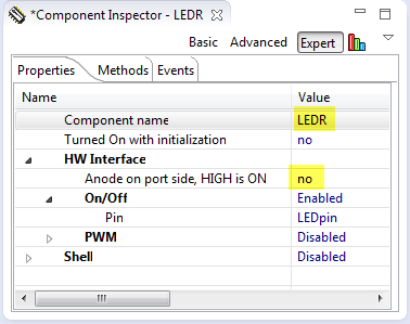
LEDR Settings
Linking to Microcontroller Pin
According to the FRDM-KL25Z Schematics (SPF-27556_D).pdf, the RGB LED is connected to following pins:
- Red: PTB18
- Green: PTB19
- Blue: PTD1
So I need to assign the pin to the LED component. For this, I unfold the LED component with clicing on the small triangle on the left side:
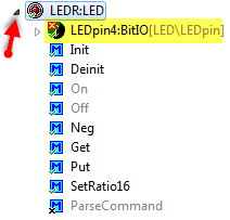
Unfolded LED
Then I select the LEDpin to show the properties in the Component Inspector. This shows some items in red as they are not assigned yet:
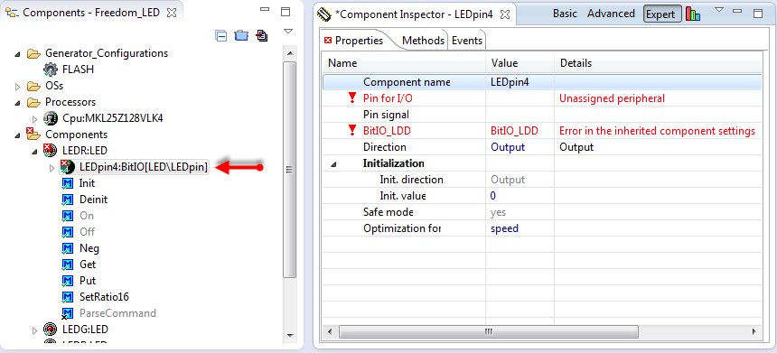
Selected LED Pin
I assign PTB18 as pin:

Assigning port pin
💡 With CW for MCU10.5, I can type in the port name and it will filter automatically the entries. For earlier CodeWarrior versions I would need to select the pin from the list.
- Setting up port and adding bit fields
Next I configure the pin as output, and mark it for auto initialization so I do not need to call the initialization of it in my application:
The Field Name has to match the field name I used in the LED component.
Hint: If I specify the optional ‘Pin Signal’ name, then Processor Expert will document it in the list of pins used.
Optionally I can assign a name for the pin/signal so Processor Expert can generate a pin list for me:

Red LED Signal Name
I need to do the same procedure for the blue and green led. It is just that they use different pins:

Green LED settings

Blue LED Settings
Wait Component
As I want to busy wait between the LED toggling, I add the ‘Wait’ component to the project:

Adding Wait Component
Generating Code
Now I have all my components together, time to generate code. For this I use the toolbar button:

Generate Processor Expert Code
This generates the code for my components:

Generating Code
Adding LED Code
The application main() is inside ProcessorExpert.c, where add my LED demo code:

LED Code
Hint: An easy way to add code and function calls to components is to use drag & drop.
Build
I build the project with the menu Project > Build Project or using the ‘hammer’ icon:

Building Project with Hammer Icon
At this point there should be no problems, so the Problems view should just show empty:

Empty Problems view with no problems
Debug
To download and debug, I press the debug toolbar icon. An annoying thing in Eclipse is I first need to *select* the project first to select the right debug configuration:
So I select the project, then hover over the icon to make sure my project is selected. Otherwise I use the small drop down of the debug toolbar icon to select the right configuration:

Starting Debugger
This will start the debugger, and I can use the toolbar items in the Debug view to step through my code:

debugging the application
Source Code
The project I have created in above steps can be downloaded from this link.
Summary
The steps presented here are really generic, and work for many boards and microcontrollers, especially for the Kinetis family. All what I need to know is the information to which pin the LED’s are connected. With this it is very easy to create a bare board (without RTOS) application blinking LED’s.
Happy enlightning 🙂

Pingback: S-Record Generation with gcc for ARM/Kinetis | MCU on Eclipse
Pingback: OpenSDA on the Freedom KL25Z Board | MCU on Eclipse
Pingback: Tutorial: Accelerating the KL25Z Freedom Board | MCU on Eclipse
Pingback: Tutorial: Freedom with FreeRTOS and Kinetis-L | MCU on Eclipse
Pingback: Tutorial: Touching the Freedom KL25Z Board | MCU on Eclipse
This is an excellent example, shows how to use CW 10.3 and Processor Expert both on a small easy to understand example.
LikeLike
Pingback: Tutorial: USB CDC with the KL25Z Freedom Board | MCU on Eclipse
Great! But OK board is super. The question is where to buy alone microcontroller? Is possible to buy in Poland?
LikeLike
Hello, not sure, but you should be able to get it through Farnell or any other distributor. They should have a Presence in Poland.
LikeLike
Have you changed the LED bean since you wrote this? I’m not seeing the LED at all under the alphabetical list, but LOTS of what look like board-specific LEDs including FRBD_KL25Z_LEDRGB_RED (and GREEN and BLUE.) I guess I should be using these logical device drivers?
LikeLike
No, the LED bean has not changed, but Freescale added their own LED LDD components now. So you could use these if you want, they are using a similar approach as my bean. My bean is universal (works for all architectures), while the Freescale LDD LED ones are only working for Kinetis and ColdFire+.
LikeLike
Further to above, I have imported the Wait package, and can’t see that in the list, either. This is CW 10.3, build ID 120924.
LikeLike
Maybe your component list has not been updated. It does it automatically for me (Windows 7). Can you try to right click on the Component Library view and use the ‘Refresh’ menu? then it should show up.
LikeLike
Ah, should have thought of that. I couldn’t see any obvious way to refresh (didn’t know about right-click.) I’ve got this on a WinXP VM. As it happens, I’d shut it down; now I’ve fired it up again, it’s all there. I now have a copy of Win7 – is there any benefit to moving over to that? (Both VMs have access to the CW workspace.)
LikeLike
I’m using Win7 32bit and 64bit, but natively (no VM). I think that using Win7 vs XP there is no real benefit, apart of that all the new stuff is focusing on Win7.
LikeLike
I’ve got all this building just fine – tried it on WinXP and Win7. HOWEVER (and it’s a big however) I’m unable to get CW to see the board. I’ve picked up and installed the latest PE Micro drivers but when I plug in the board (I’ve tried two different ones) on both XP and 7, I get a thing popup which finds USB storage on there, but P&E Connection Assistant always comes up (No Device Available) even with re-connections and re-boots. I know this isn’t an Erich Problem, but I’m not entirely sure where I should be looking for help as P&E Micro’s support proved utterly useless when I had a similar problem with the Multilink for HCS08. (It took two lots of new drivers to fix that.) Any pointers as to a half-decent support channel would be most welcome! I’m certainly stuck playing with 8-bit stuff for the time being. (And my TI Stellaris LaunchPad, but I’m probably not allowed to say that here 😉
LikeLike
The LaunchPad is a fantastic board! Freedom of speech (in good sense) is important to me :-). I published a while back a how-to-install tutorial in freescale community thread/93204, but looks with the migration to the new forum this is lost. I see if I can dig this out.
LikeLike
Pingback: Removal of Processor Expert for a Project | MCU on Eclipse
Pingback: Tutorial: printf() and “Hello World!” with the Freedom KL25Z Board | MCU on Eclipse
Hello.
I can see from the CPU component properties that the core clock is working at 20.97152 MHz in FEI MCG mode. With this configurtion, I believe the crystal is not used at all.
The FRDM-KL25Z is advertised as being able to work up to 48 MHz. For this, the setting would have to be to use the PEE mode using the 8 MHz external crystal with 22pF capacitor load. Is this correct?
I tried this setting but Processor Expert tells me that the max core clock is 20 MHz.
Do you have any information on the settings to use the MCU at 48 MHz?. Is there any source code for the out-of-the-box project that comes pre-programmed?
Thank you.
LikeLike
Hello,
yes, 48 MHz are possible. Have a look at my other FRDM post which is using 48 MHz: https://mcuoneclipse.wordpress.com/2012/10/07/tutorial-usb-cdc-with-the-kl25z-freedom-board/
I hope this helps,
Erich
LikeLike
Great.
Thanks. I just received my Freedom board a few days ago and discovered this blog while searching for information. Haven’t looked at all the posts, but it looks great. Real good step-by-step instructions.
Thanks for the reply. I’ll take a look at the post.
LikeLike
Pingback: Copy my CodeWarrior Project | MCU on Eclipse
Pingback: Tutorial: Bits and Pins with Kinetis and the FRDM-KL25Z Board | MCU on Eclipse
Pingback: Arduino Data-Logger Shield with the FRDM-KL25Z Board | MCU on Eclipse
Hello,
I’m trying out my FRDM-KL25Z, and selected this tutorial as my 1st project.
However, you have stopped short of explaining the debugging procedure.
There are several settings upon clicking the debug button,…when does one select a particular setting ? What are the right settings for this project?
Some issues:
1. In your photo, hovering over the debug button shows the tip: ‘Debug Freedom_LED_FLASH_OpenSDA. When I do the same (with the project selected) I just get ‘Debug’ as the tool-tip.
2. When I try to debug anyway, I get an error message with a ‘No device available’ message.
However my board is connected, and I could drag other binaries to the board and run them.
3. After I do a build /build all, should I get some executable like bin/srec/s19 etc (not sure which one is the default)? But I can’t see any. When and where are the produced ?
Sorry if my questions are ‘noobish’ but I have only used 8 bit MCUs & All this is new to me.
Thank You.
LikeLike
Well, I got point (2) sorted out from this thread:
freescale community thread/301232
and
This should really be made more clear by Freescale …. it is not mentioned even in the ‘Sample Code Package’ which I tried to use & had this same error – threafter I found this blog.
But I’m still curious about (1) & (3).
Thanks
LikeLike
about point 1: the hover shows the active debug configuration. In Eclipse, make sure you have selected the project root folder in the project view, then the ‘debug’ icon will know which project to debug (this is one of the few Eclipse things which really is not done very well). So always select the project to make it ‘active’. If you just have ‘Debug’, this means that you do not have launched a debug configuration yet. Click on the small triangle on the right side of the ‘debug’ icon and select the configuration you want. If the list is empty (Eclipse populates it with your history), select the sub menu ‘Debug as…’ > CodeWarrior Download. This should lead you to the correct configuration.
As for point 3: this post explains how to generate S19 files with gcc: https://mcuoneclipse.com/2012/09/13/s-record-generation-with-gcc-for-armkinetis/
Hope this helps,
Erich
LikeLike
Hello,
looks like you have sorted out point 1 and 2: you need to load the Debug Application.
For point 3: the output binaries are placed in the output folder as specified in the build settings. For KL25Z it should be a folder named ‘FLASH’.
As for generating the S19 file: see this post:
Hope this helps,
Erich
LikeLike
Thank you for your answers!
I finally got my 1st project working on the board. 🙂
LikeLike
Pingback: LED’s for Kinetis, simplified | MCU on Eclipse
Hello,
Very useful blog I must say, helped me a lot to get started with the freedom board.
However, there is one tiny problem that I am facing while loading the program on the board.
When I use the “flash programmer” button to load the .elf to the board, it does not start running after the writing is complete. I get no effect even if I press the physical reset button. The MCU starts running my program ONLY when I unplug and reconnect the USB connection.
I have the debug application loaded on the Open SDA.
Any idea am i doing wrong? Or is it meant to be this way?
LikeLike
Hello,
no, that would not be normal. Strange, when I tried this myself after your report, I had somehow the same issue. But when I retried it, it works since then?
If the program does not start with the reset button, it could be that the reset button is disabled (you can map it to a normal input/output pin). But I think this is not the problem, as at reset, the pin is used as normal reset pin.
I only could imagine that for strange reasons the OpenSDA prevents the CPU to reset through the reset button.
Again, it works now for me. Maybe I need to play around in order to reproduce it again.
LikeLike
hat is a good possibility, I will try to remap the reset button and try it out.
The actual reason I’m here again is to ask you how to report any bug to freescale.
I noticed a mistake in the documentation. The docs say PTE0 (UART1_TX) goes to J2-20. Which actually isn’t the case. It goes to J2-18. I found this out by probing the pcb with a meter as I couldn’t get the UART1 to work. After I swap my TX connection to J2-18 the thing works.
LikeLike
In my schematics I have downloaded, PTE0 (Pin1) goes to D14 which is on J2-18 on my schematics.
So it is correct on the one I use (http://cache.freescale.com/files/soft_dev_tools/hardware_tools/schematics/FRDM-KL25Z_SCH.pdf?fpsp=1).
Which one are you using?
As for reporting bugs: https://www.freescale.com/webapp/servicerequest.create_SR.framework
LikeLike
There is a pinout table provided in the FRDMKL25ZUM.zip (FRDM-KL25Z User’s Manual). That one says PTE0 is on J2-20.
LikeLike
i am using Codewarrier 10.3 and on adding LED Bean i am not getting LLD Options on adding LEd Bean , how to resolve that.
LikeLike
I have recently simplified (see https://mcuoneclipse.com/2012/12/27/leds-for-kinetis-simplified/) and extended the LED component (see https://mcuoneclipse.com/2012/12/29/pwm-and-shell-for-a-led/). So there is no LDD option needed any more in the latest version. If you want/need the previous version (e.g. 1.046), you can download it from http://steinerberg.com/EmbeddedComponents/LED/home.htm
LikeLike
You used commands like: “_Neg()” and “_Waitms(_)”. Where I find more commands for programming?
LikeLike
The wait routine is from the Wait component (http://steinerberg.com/EmbeddedComponents/Wait/home.htm) you can add.
The _Neg() method is one of the LED component. The LED component has evolved a bit, and the latest and greates is shown in https://mcuoneclipse.com/2012/12/27/leds-for-kinetis-simplified/ and https://mcuoneclipse.com/2012/12/29/pwm-and-shell-for-a-led/
LikeLike
Hi
great tutorial Thanks
I got a question:
To program and debug my FRDM- KL25Z should I buy the codewarrior or some software?
LikeLike
Hi, yes, there are several tool chains (beside CodeWarrior available), e.g. IAR, CodeRed or CoCoox. They all come with a free of charge (limited) version (see details of each offering, but typically this is limited to 64 KByte code size). So you need development tools to debug, but typically it is free of charge up to a certain limit.
LikeLike
Thanks
I’ll start with these microcontrollers
Please suggest which of these I must download?
http://www.freescale.com/webapp/sps/site/overview.jsp?code=CW_SPECIALEDITIONS
LikeLike
Which Microcontroller are you going to use? The Freedom Board with the KL25Z? Then I suggest
Special Edition: CodeWarrior for Microcontrollers 10.3 (Eclipse, Offline)
as this one comes for free up to 64 KByte of code size debugging for the KL25Z.
LikeLike
The evaluation board is this:
http://www.newark.com/freescale-semiconductor/frdmkl25z-proto-bundle/eval-proto-kit-kinetis-kl25z-freescale/dp/46W9881?in_merch=Featured%20Products&in_merch=Popular%20Products&MER=PSPSO_S_C_FreescaleSemiconductor_FreescaleSemiconductor
LikeLike
That’s the normal KL25Z freedom board with a prototype board. CodeWarrior for MCU10.3 free special edition works with this one.
LikeLike
Thanks, I appreciate your help
LikeLike
Hi, my cpu model is: MKL25Z128FRDM 1N97F XCTAA1230E, But in the code warrior shows as: MKL25Z128VLK4. I don’t know if this can affect in any way in the moment of doing the “debug” part.
LikeLike
No, this will not be an issue. 1N97F is the mask set of the processor. The mask set is the ‘hardware version’. MKL25Z128VLK4 identifies the processor (Kinetis L Family, Z128 derivative, while the VLK4 identifies the package. You find more information on this here: http://www.freescale.com/webapp/sps/site/prod_summary.jsp?code=KL2&tab=Buy_Parametric_Tab&fromSearch=false
LikeLike
Hi Erich, First of all. Congratulations for your work. It’s amazing. You have built alot.
I am with some issue. I can’t Add the LED component, i’ve download from:
http://steinerberg.com/EmbeddedComponents/LED/home.htm
and it doesn’t show on Components Library. Even if i refresh.
I see there is a standart LED component from CW. Shouldn’t you rename to LEDR in your Bean?
Thank you
LikeLike
Hello,
if the component has properly be imported, you should have a folder C:\ProgramData\Processor Expert\CWMCU_PE5_00\Beans\LED on your system. Does this folder exist? If not, then the LED component has not been imported properly.
LikeLike
Hello Erich,
Yes the folder exists. Well this sounds wierd, but worked. Just the Icon was diferent. =)
Thanks alot
LikeLike
Erich, I imported the components properly but I am not seeing the configuration of the LED components like yours. I don’t see the LDD and Hardware interface settings in my imported LEDR for example.
LikeLike
There is the possibility that the LED component conflicts with a similar one already installed by CodeWarrior (LED for DSC). I have created a clone of the LED component named LEDbit and put it into package in http://steinerberg.com/EmbeddedComponents/LED/LED_1.050_22.02.2013.PEupd
Can you try if this helps?
LikeLike
Hi Erich, I’m having the same issue as Smilinsteve. I’ve successfully added the LED clone LEDbit with no change (LDD not shown under Hardware Interface). I am using Codewarrior 10.3. Have there been any updates on this?
LikeLike
Hi Sean,
not sure what your exact problem is. So yes, the LED component has made some updates, and it is using a BitIO component instead of a LDD one. Maybe you can send me you project/screenshot to the email address listed on the about page?
LikeLike
Thanks Erich,
my question was better worded by codenoob2013 below. I was able to get it running from your response and your other tutorial “https://mcuoneclipse.com/2012/12/27/leds-for-kinetis-simplified/”
LikeLike
Hi Sean,
ok, good to know that it works now for you 🙂
LikeLike
Hi Erich,
I have trouble setting up the LED component as you instructed. I am using FRDM-KL05Z board.
This is my configuration window look like: http://s17.postimage.org/5tbauhblb/LED1.png
The pin only shows “LEDPin” or “GenericBitIO”. I can’t select a Pin I need.
If I just select “LEDPin” and go forward to generate the code, the comments of the code shows that it is using PTB7 as the pin. However, KL05Z uses PTB8, PTB9, PTB10 respectively for three LED lights. And of course the generated code doesn’t light up the LED, since the pin is wrong.
If I select “GenericBitIO”, it complains that “No Inherited component assigned”
Do you have any idea what is happening here?
Thanks a lot!
LikeLike
Hello,
In the LEDpin (BitIO) component you need to select the proper pin there.
In any case: there is a KL05Z project available here: https://github.com/ErichStyger/mcuoneclipse/tree/master/Examples/FRDM-KL05Z/KL05Z_FreeRTOS
LikeLike
Thanks Erich. Didn’t know LED contains another component I need to configure. Thanks again.
LikeLike
Hi Erich,
First of all, thank you for these tutorials, they are really useful.
I tried to make all the tutorials that you had post, in all of them I build the project without problems but when I try debug, the project goes wrong. In the debug window the program says:
-LED_FLASH_OpenSDA[CodeWarrior Download]
ARM Processors, LED.elf(Suspended)
Thread[Id:0x0](Suspended:Signal ‘Halt’ received.Description:User halted thread.)
Then in the Disassembly window there is a marked line that says:
-push (r7,1r) –> it seems that the program is stopped here.
Do you have any idea of what is happening here?
Thank you very much!!!
LikeLike
Problem solved!
Thanks for the tutorials!
LikeLike
Hi Sergi,
good to hear that 🙂
LikeLike
Hi Sergi! i have the same problem.. can u tell me how to fix it? thanks !!
LikeLike
On my LED component inspector under HW Interface, it doesn’t have the LDD drop down to add the GPIO to the LED component, what I am missing to get this option?
LikeLike
Sorry! Just read over the comments! I’ll try what you instructed above!
LikeLike
Hi Liz,
yes, sorry. I should have added a note at the beginning of the post about this. I did this now, so hopefully that makes sense now.
LikeLike
Hi Liz,
yes, that LED component has been simplified so it is easier to use now. Basically no need to use an LDD component any more, the BitIO will do it. Please see LED’s for Kinetis, simplified | MCU on Eclipse
LikeLike
Hi Erich,
Two questions…
I am having trouble getting OpenSDA to work and I noticed that in the Connections screen shot above you have both Open SDA and P&E checked. Is there a reason for this?
Can you please point me to a good tutorial that really targets getting OpenSDA going?
Thanks again in advance – your site is a brilliant resource.
Bryon
LikeLike
Hi Bryon,
thanks, good to hear that things are useful. As for the debug connection screenshot: you only need one. I just had selected two so it creates both the P&E and the OpenSDA connection. Have you loaded the OpenSDA Debug Application on your board? See https://mcuoneclipse.com/2012/09/20/opensda-on-the-freedom-kl25z-board/. If you receive your board, then it has the OpenSDA Mass Storage Device (MSD) bootloader on it, which can be used to copy S19 files. But you cannot debug with it. You need to load first the DebugApp.
I hope this helps.
LikeLike
HI Erich
I followed the step by step Instruction given in the blog but i am having problems with the LED
I Downloaded the LED file with the link given, But
And the GPIO LDD option is not available, And i not able the share the LED
Please let know how to go ahead with the same
LikeLike
Hi Nikhil,
have you seen https://mcuoneclipse.com/2012/12/27/leds-for-kinetis-simplified/ (it is referenced at the beginning of the tutorial). I have greatly simplified the usage of the LED. Maybe this is your problem?
LikeLike
Hi Erich,
In your post when you add an LED, in the HW Interface dropdown you see GPIOLDD option
I downloaded the LED component from the link given in your post and added the same
But when i add the same to my project the GPIOLDD option is not there, And even when i tried adding a GPIO_LDD component its giving me an error saying
Peripheral is already being used by component BitIoLdd1
And when i go to BitIoLdd1 its giving an error saying Error in inherited Component setting
If i download your project and check your LED setting the GPIO_LDD option is still not available
LikeLike
Hi Nikhil,
I appologize: writing tutorials has a big drawback. When things get improved and steps might change a little bit, then this means updating the tutorials too :-(. I was deliquent not doing this, and hoping pointing to the post with the changes is enough. I was simply wrong, I should have updated the steps in the first place as I agree it might be confusing. So with a big fanfare: I have updated the tutorial with the updated/simplified steps for the actual LED component. So no need any more fumbling with the GPIO_LDD stuff :-). Please refresh things in your browser, and you should now see the same as in CodeWarrior for MCU10.5. Again, I appologize, and hope now it works like a charm 😉
LikeLike
Hi Erich,
Any links for the same.
I am struggling with this for a very long time
Erich, Please help me out with this
LikeLike
Hi Nikhil,
any links for what exactly?
LikeLike
Thank you Erich got it!!!!!!!!!!!
Sorry for the previous question,Thought that you had uploaded another tutorial for the same.
LikeLike
You are welcome. And no problem 🙂
LikeLike
Pingback: Tutorial: Timer (LED) with Processor Expert for Kinetis | MCU on Eclipse
Pingback: Controlling NXP Freedom Board RGB LED with openHAB and Raspberry Pi | MCU on Eclipse
Hi Erich
i’m using kinetis studio, and these examples are done in Codewarrior. My question is… Can I follow the same steps for kinetis studio?
I’m trying to follow the same steps with accelerometer example that you did, but i have doubts about it.
LikeLike
Hi Cesar,
that example with the LED still applies for KDS, but some dialog are somewhat different, but the concept is still the same.
There is a similar tutorial for the accelerometer here: https://mcuoneclipse.com/2012/09/21/tutorial-accelerating-the-kl25z-freedom-board/
I hope this helps,
Erich
LikeLike