The semester started last week. Ideally I wanted to have the boards for the new S robot (see “Zumo Robot with WiFi and GPS“) ready in the first week. But our manufacturer was not able to get the four-layer boards with parts populated and delivered in that time frame. Until the new boards arrive, we have anyway plenty of things to cover. One thing is to build a prototype shield to host several distance sensors, nRF24L01+ and Bluetooth transceiver:

Sumo Robot with Sensor Shield and Sensors
Students will get the Eagle files, and then can adjust it for their own needs, and create their own custom board. The shield hosts several connectors for:
- Bluetooth module
- nRF24L01+ module
- I2C Sensor module
- Ultrasonic module
- 7 four-pin sensor modules
- Extended sensor module with 3 pins
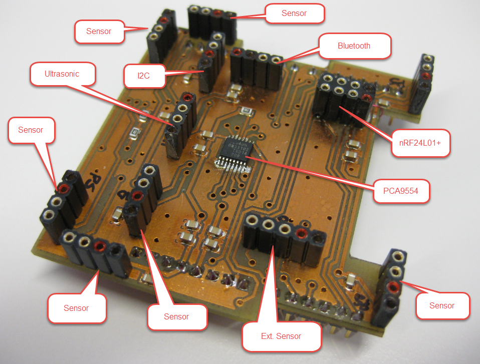
Sensor Shield Connectors
Each of the module connectors have Vcc, GND and the digital (or analog) pins available. The connectors are designed for the Pololu infrared and distance sensors, but any sensors can be used. Several pins are directly connected to the shield pin rows. To extend the number of I/O pins, the I2C IO Expander IC PCA9554A is used.
The Shield is compatible with any Arduino (3.3V) or Freescale Freedom boards (e.g. FRD-KL25Z).We have two variants of the JY-MCU Bluetooth modules, so they fit in one or the other way:
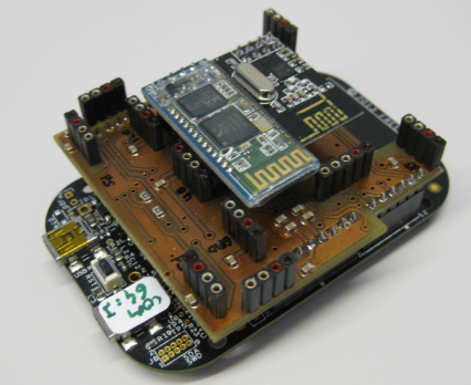
Shield on FRDM-KL25Z
With providing the Eagle files, I think this opens up for creativity. In any case, I have now a nice shield for my other FRDM boards so I can use them with external sensors, Bluetooth or the nRF24L01+ 2.4 GHz transceiver.
I have attached the schemata of the board: INTRO Robot Base Board Schematic.
Happy Shielding 🙂

What a GREAT little board for the the Freedom/Arduino footprint. I am drooling for one already. 😉
Are the boards available to the general public?
What is the source of the headers soldered onto the board? I think I might like to get some.
Coloring the plus and minus pins with a marker is a good idea. I’ll bet you save some of the “magic smoke” that way.
(I don’t know if it is taught in Europe, but when I went to electronics school, we were taught that everything electronic runs on Magic Smoke. … Because, if you let the smoke out, it quits working. 😉 )
LikeLike
I plan to publish the board EAGLE files to the public, so everyone could do his own board (after we have fixed an issue I have detected yesterday). We will probably produce a small batch internally. If you are interested, send me your contact data to the contact email address on https://mcuoneclipse.com/about/ and I should be able to send you one (probably unpopulated).
About the headers: I need to check next week for the part number, but they are commonly available from Farnell or other distributors.
And yes: as the boards have no silk screen, I usually mark the pins with color markers. Simply to avoid that magic smoke coming out of the electronics 🙂
LikeLike
Pingback: BBQ Smoker Monitoring Robot | MCU on Eclipse
Pingback: Enabling/Disabling FXOS8700CQ Device Needs a Delay | MCU on Eclipse
Pingback: Sumo Robot Sensor Shield | MCU on Eclipse