
Found an interesting behaviour with the Freescale FXOS8700CQ on the new Sumo Robots (see “Sensor and Communication Shield for Sumo Robot“): when enabling the accelerometer/magnetometer, it actually did not work:
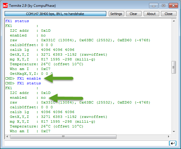
Failed to Enable FXOS8700 Accelerometer
First I thought it was a problem of my robot, but I had the same effect with the same device present on the FRDM-K64F board: enabling did not work. Until I realized with my change log on GIT that I had changed as well the clock speed of the device. So I was wondering if the speed somehow has an impact?
So I debugged my code and stepped through the function to check what is going on:
uint8_t FX1_Enable(void)
{
  uint8_t val, res;

  res = GI2C1_ReadByteAddress8(FX1_I2C_ADDR, FX1_CTRL_REG_1, &val);
  if (res!=ERR_OK) {
    return res;
  }
  val |= FX1_ACTIVE_BIT_MASK; /* enable device */
  return GI2C1_WriteByteAddress8(FX1_I2C_ADDR, FX1_CTRL_REG_1, val);
}
And indeed: with debugging line over line it magically worked!
With a lot of guessing and trial and error, I have found out that it fails if there is no breakpoint between the read access and the write access. Wow! I checked the reference manual of the accelerometer device, but no indication that I was doing something wrong. I checked the example code provided by Freescale, and there it always writes the CTRL_REG1 without reading it before. I thought I did not something wrong?
The reference manual says for the ACTIVE bit in the CTRL_REG1:
“The active bit selects between Standby mode and Active mode. The default value is 0 (Standby mode) on reset.”
I did not pay much attention to that “on reset”, but could it be that the bit is active only after a reset? I vaguely remember something reported somewhere else. Or could it be that the device makes an internal reset if I set that bit somehow?
Checking for any necessary needed delays, I only have found this for the rst (reset) bit of the CTRL_REG2 register:
“The I2C and SPI communication systems are also reset to avoid corrupted data transactions. The host application should allow 1 ms between issuing a software (setting rst bit) or hardware (pulsing RST pin) reset and attempting communications with the device over the I2C or SPI interfaces. When the SPI interface mode is desired and multiple devices are present on the bus, make sure that the bus is quiet (all slave device MISO pins are high-z) during this 1 ms period to ensure the device does not inadvertently enter I2C mode. Please see section 6.2.3 for further information about the interface mode auto-detection circuit.”
So I decided to add a 1 ms delay:
uint8_t FX1_Enable(void)
{
  uint8_t val, res;

  res = GI2C1_ReadByteAddress8(FX1_I2C_ADDR, FX1_CTRL_REG_1, &val);
  if (res!=ERR_OK) {
    return res;
  }
  WAIT1_Waitms(1); /* for unknown reasons, need to wait for 1 ms after reading the register */
  val |= FX1_ACTIVE_BIT_MASK; /* enable device */
  return GI2C1_WriteByteAddress8(FX1_I2C_ADDR, FX1_CTRL_REG_1, val);
}
And guess what? It magically worked that way :-).
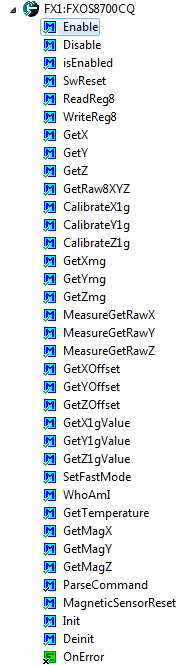
FXOS8700CQ Component
And while working on that component, I have now added a SwReset() function and command line interface too :-).
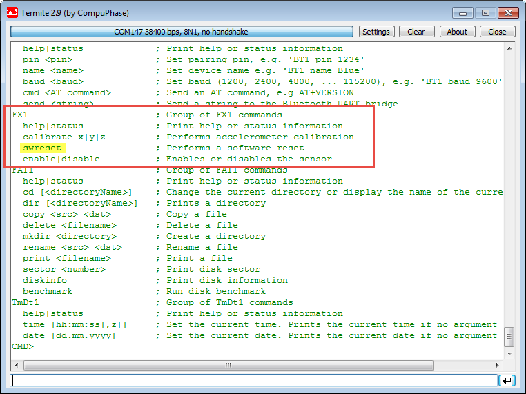
Additional swreset command
Summary
Sometimes devices have hidden/undocumented (???) timing issues. As much as I hate these magical realtime delays, sometimes they are the only way to solve a situation. I have ‘fixed’ now the FXOS8700CQ component code on GitHub, and the fix will be included in the next release. Unless someone else has an explanation what is going on here?
Happy Enabling 🙂

You are a Guru of embedded. Sometimes I look at my code over and over and over again. its sickening that such things are so much hidden. Thanks for sharing on github. Am teaching my students to use git and github as part of embedded lab, so they will benefit from this in future 🙂
LikeLike
Yes, I know it is very sickening, but adds experience you cannot learn from books ;-). What I have learned is that for myself (and students) it is important to think about what could go wrong if I would had implemented that device? What would be a problem for such a device. I think the hardware engineers probably did not think about that someone would read a status register and write it right away? Sounds strange, but unfortunately this is the reality 😦
LikeLike
I use your Enable() routine and it works well on my FRDM KL26Z. Also I added some functionalities to this component. See my Github http://github.com/fouge if you want to integrate some of them (these are init configurations)
LikeLike
thanks for sharing! I absolutely need to check them out as soon as I can and integrate what you did. Thank you, thank you, thank you!
LikeLiked by 1 person
I wrote a blogpost today http://t.co/zMBzsGxv8X
LikeLike
I updated the component : it now supports FIFO in Fill and Cirular mode with the selection of the interrupt signal.
http://cyrilfougeray.com/2014/10/21/processor-expert-components-for-frdm-fxs-sensors/
LikeLike
Nice blog. Very helpful when doing Freescale development.
Might be helpful to those using Freescale sensors: We have used the FXOS8700CQ and the FXAS21002 gyroscope on this Ardunio shield http://www.freescale.com/webapp/sps/site/prod_summary.jsp?code=FRDM-STBC-AGM01
in a demo of the Esquilo board (http://esquilo.io).
The code is all here: https://github.com/esquiloio/lib
The sensor code is at:
https://github.com/esquiloio/lib/blob/master/sensors/fxos8700/fxos8700.nut
https://github.com/esquiloio/lib/blob/master/sensors/fxas21002/fxas21002.nut
The demos are web apps that communicate positional data in real-time from the Esquilo. One plots all 9-axis in real-time, while the other manipulates a 3D image in the browser to mirror the board movements:
https://github.com/esquiloio/lib/tree/master/demos/imu
https://github.com/esquiloio/lib/tree/master/demos/esquilo3d
LikeLike
Forgot to mention that screenshots are here:
https://www.esquilo.io/docs/#!demos
LikeLike
Nice project on Kickstarter, and thanks for sharing. To me it would be the most useful if the code would be plain C, have you considered that approach too?
LikeLike
Hi Erich,
Thank you.
Definitely C would be good and we can, and probably will, bring it into C. The Esquilo is based on a Freescale Kinetis K64 running their MQX RTOS, so we can definitely do so.
The Squirrel VM runs on top, is dynamic and has a full source debugger from our web IDE. The demos are intended to show that using the floating-point coprocessor it is practical and easy to do some pretty heavy calculations in the dynamic environment and have the advantages that offers (skipping compilation/download step, tinkering around on a remote command line – e.g. led.on(), led.off(), etc.).
These demos have been extremely popular to base projects on at Hackathons, so we are considering bringing them in as C and exposing them to the Squirrel VM:
https://www.hackster.io/guruNYC/drift-visualizer
https://www.hackster.io/5098/distance-motion-capture
LikeLike
Great work! I am working on the AGM01 board too but with beaglebone black for interfacing and generating values. I am writing code in c++. I am a beginner and a have a lot of questions about the links above. I am stuck in the development and would appreciate any feedback.
LikeLike
Hi Priyank,
if you are a beginner, I recommend that you start with C, and not C++: that would make many things probably easier.
LikeLike
Hi Priyank,
I assume this is your code:
freescale community thread/356821
If so, I’d start by adding checks for each opResult, even if it’s just a printf of the value. I haven’t used i2c on the BB, but it could be a setting or a file permission, or something else. Hopefully the result code will give a good hint.
– Patrick
LikeLike
Hi, i try this code and the complete blog of this device in a frdm k64 f and works perfect, i apply to my project , a car. I buy the components and made my pcb ; i wire the device like said the data sheet but , i dont know what can i do with the INT1 and INT2 pins, i try connected to the microcotroller and with the code of the example but nothing happen , i have no data from the accelerometer like i did in the frdm board. Do you know if i need to send some data trought INT1 and INT2 or let in some fixed state ?
LikeLike
Hi Marcela,
INT1 and INT2 are interrupt lines from the sensor to a microcontroller. You don’t need these lines if you dont’ want to use interrupts.
LikeLike
Hi,
Does anyone has MSP430 code for FOSX8700 SENSOR?
Thanks!
Peter
LikeLike
We are using the FXOS8700 for vehicle detection purpose.
My pic24 ic initiates the i2c communication with FXOS , reads, and writes the data to it.
Am using the vector magnitude interrupt for detecting the presence of any vehicle on top of the sensor where sensor is burried on the road.
The interrupt snippet is :
void __attribute__((__interrupt__, auto_psv)) _INT0Interrupt(void)
{
INTCON2bits.INT0EP=~INTCON2bits.INT0EP;
IFS0bits.INT0IF = 0;
PORTBbits.RB15=0;
WriteByte_I2C1(SLAVEADDRESS,FXOS8700CQ_M_CTRL_REG1, 0x1d|0x01);
delay_ms(2000);
data1=ReadByte_I2C(SLAVEADDRESS,0x5e);
if(data1==0x00)
{
if(flag==0)
{
send_distance4(0);
flag=1;
flag1=0;
}
if(flag==1)
{
}
}
else if(data1==0x02||data1==0x06)
{
if(flag1==0)
{
send_distance4(1);
// delay_ms(500);
flag1=1;
flag=0;
}
if(flag1==1)
{
}
// send_distance(temps,0x77);
}
WriteByte_I2C1(SLAVEADDRESS,FXOS8700CQ_M_CTRL_REG1, 0x09);
delay_ms(5000);
delay_ms(20);
}}
This logic works well but when the temperature goes high, there is no response from the sensor. We noticed that the x,y,z values change wrt temperature.
Hence could you suggest any better logic or way to solve this problem?
The FXOS initialisation is
void init()
{
standby(); // Must be in standby to change registers
delay_ms(20);
// active();
//delay_ms(2000);
// x/y/z accel register data stored here
WriteByte_I2C1(SLAVEADDRESS,FXOS8700CQ_CTRL_REG1, 0x28);//400hz 2.5ms
WriteByte_I2C1(SLAVEADDRESS,FXOS8700CQ_CTRL_REG3,0x02); //active high interru[t]
WriteByte_I2C1(SLAVEADDRESS,FXOS8700CQ_M_CTRL_REG1, 0x1d|0x01);
WriteByte_I2C1(SLAVEADDRESS,0x52, 0x00);
WriteByte_I2C1(SLAVEADDRESS,0x69, 0x1b);
WriteByte_I2C1(SLAVEADDRESS,0x6a, 0x00);
WriteByte_I2C1(SLAVEADDRESS,0x6b, 0x32);
WriteByte_I2C1(SLAVEADDRESS,0x6c, 0x3e);
WriteByte_I2C1(SLAVEADDRESS,FXOS8700CQ_M_CTRL_REG1, 0x09);
delay_ms(2000);
active();
active();
}
LikeLike
Every sensor of any kind is typically sensitive to temperature. Or in other words: sensors in general measure the temperature. So you would have to compensate the temperature effect/drift.
The other thing I notice is that you are using a delay in the ISR? This is not something you should do at all 😉
LikeLike