
One of the ‘goodies’ of the FRDM-KL46Z is the Freescale MAG3110 magnetometer. The MAG3110 is a tiny 2×2 mm device:
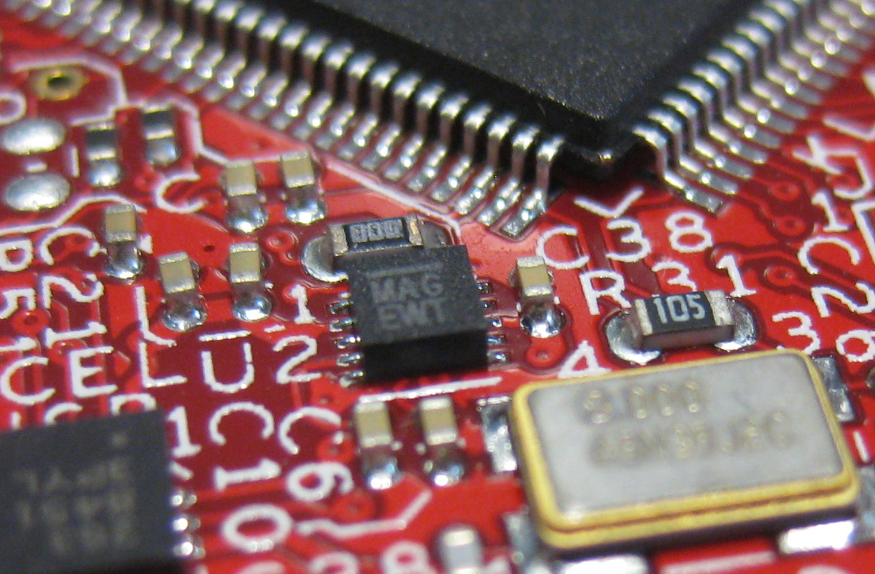
MAG3110 on FRDM-KL46Z
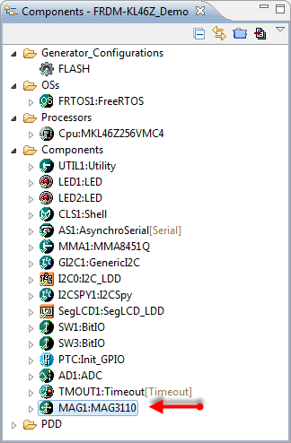
What was missing so far is a Processor Expert component for it. This post is about closing this gap…
MAG3110 Magnetometer
The Freescale Xtrinsic MMA3110 is a 3-axis digital magnetometer (from the MAG3110 Datasheet):
- I2C Bus Interface up to 400 kHz
- 16bit X, Y and Z magnetometer values with 15bit user offset
- Full scale ±1000 µT and a sensitivity of 0.10 µT
- ‘Fast’ mode to read only 8bit values and auto-address-increment
- Multiple data rates and oversampling rates
- Polling or interrupts
- Temperature sensor (needs user calibration, see below)
Component Properties
The component has settings to connect to the I2C bus and to enable the optional interrupt pin:
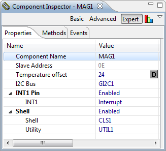
MAG3110 Properties
Additionally, there is an optional command line shell interface.
Temperature Sensor
The MAG3110 has a register to read out the temperature (DIE_TEMP, address 0x0F). What puzzled me was that I was always reading 0xff or 0x00 as temperature. According to the data sheet, it shall report the temperature in °C, but is not factory trimmed:
“The register contains the die temperature in °C expressed as an 8-bit 2’s complement number. The sensitivity of the temperature sensor is factory trimmed to 1°C/LSB. The temperature sensor offset is not factory trimmed and must be calibrated by the user software if higher absolute accuracy is required. Note: The register allows for temperature measurements from -128°C to 127°C
but the output range is limited to -40°C to 125°C. The temperature data is updated on every measurement cycle.” (Source: MAG3110 Data Sheet)
This offset can be added in the component properties.
Component Methods
The component has methods to access all functions and registers of the device:
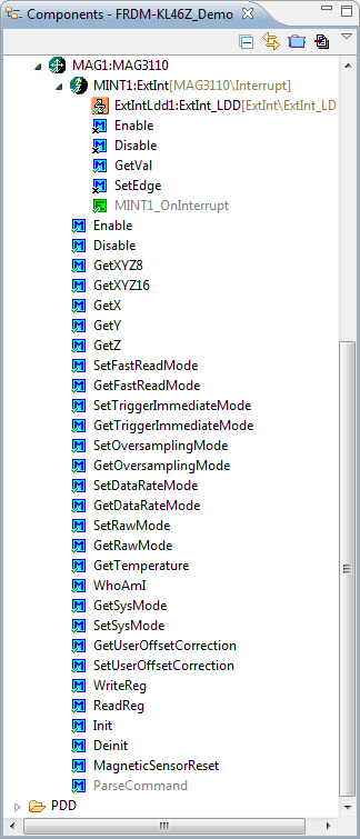
MAG3110 Methods
Example Application
I have put on GitHub here an application which demonstrates the usage of the component:
MAG3110 Example Application
Make sure you load the latest Processor Expert components from GitHub too. See this post for details.
Shell Interface
The application uses a shell interface to the MAG3110:
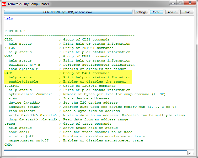
MAG3110 Command Line Interface
As the sensor is disabled by default, the command
MAG1 enable
turns it on.
With
MAG1 status
it shows the status and settings of the device:
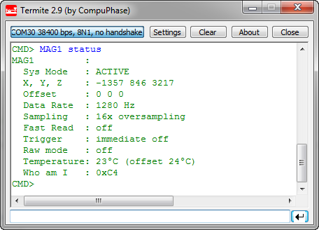
MAG3110 status
With
trace shell
it writes the X, Y and Z magnetometer values to the console:
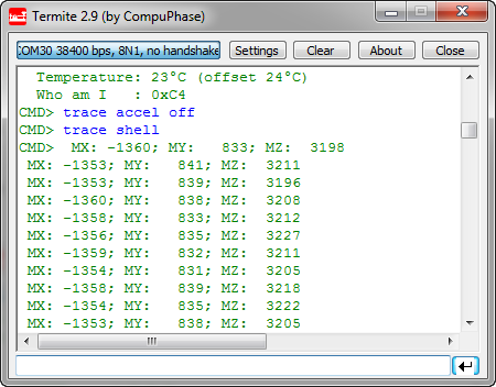
Tracing MAG3310 Magnetometer Values
trace none
turns the trace off.
The example application has the I2CSPY component added. Using it I can dump the registers of the MAG3110:
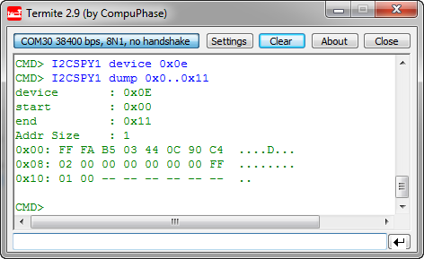
Reading MAG3110 Registers with I2CSPY
Summary
I have exported the component in the *.PEupd package on SourceForge here. The driver code is located here.
With this MAG3110 component it makes it easy for me to use the Freescale MAG3110 magnetometer sensor. I expect that the MAG3110 component and demo application will evolve over time, but so far I’m really happy with the results. Freescale has an extra eCompass software package available which I have downloaded, but not really used yet. So still more stuff to explore ;-).
Happy Compassing 🙂

Awsome Erich!!!
How about a tutorial on how to create Processor Expert components, and the tools that are required?
Very interested in creating some of my own and sharing in the future.
LikeLike
Thanks 🙂
And there is already a tutorial on this subject: https://mcuoneclipse.com/2013/03/31/tutorial-creating-a-processor-expert-component-for-an-accelerometer/
LikeLike
Thanks Erich. Will check it out.
LikeLike
Pingback: USB for the Freescale ARM Kinetis KL46Z and K21D50M | MCU on Eclipse
Hi Erich,
I am having trouble getting your KL46Z Demo to run. I have copied your demo folder into my workspace directory and imported it into CW 10.4. I build the components and then build the program and then get an error pointing to events.h. The error is on line 46: #include “RTOSTICKLDD1.h”
Where it shows the following error:
RTOSTICKLDD1.h: No such file or directory Events.h /FRDM-KL46Z_Demo/Sources line 46 C/C++ Problem
Obviously, it has something to do with the RTOS, but I have no idea where to start. Do you have any suggestions?
Also, what are some guidelines about when to use an RTOS and when to just go with a simple control program?
(I have thought that I probably didn’t need the complication factor of an RTOS for the product we have developed. It will be maintained by non-professional programmers once we go into production. The MCU program just loops through reading the inputs, writing the outputs, and communicating with an Android device via USB.)
I have assumed that adding an RTOS would just complicate things, add additional failure points, and would not add any useful functionality. Do you mind sharing your thoughts on the matter?
Lastly, I have been following your blog regularly for the past year and can’t express my gratitude enough for all that you have done for me, and my fellow newbies worldwide. It was predominately because of your blog that I decided to use the Freescale KL25Z (and now the KL46Z – which I think is great) instead of going with Atmel, PIC, ST, TI, or any of the others.
You have helped me do my job far more than I can express with these few words.
Thank you.
LikeLike
WOOHOO! Someone else had a similar problem and your answer to him worked for me.
Thanks anyway.
LikeLike
The problem about #include “RTOSTICKLDD1.h”? Yes, that might be a side effect of my SysTick change (https://mcuoneclipse.com/2013/08/30/optimized-freertos-stack-check-and-systick-for-arm-cortex-cores/) :-(. Simply remove the include line from the source file.
LikeLike
Hi Injun,
about using or not using an RTOS: if you are really only using a single loop and there is no complexity behind this loop, then you clearly do not need an RTOS. If you only do one single thing at a time, and the timing is not complicated, then an RTOS is an overkill. An RTOS makes sense if you need to do multiple things in ‘parallel’. Or if you have complex timing constraints or if you have things which needs to be interrupted. Assuming you need to check a sensor every 10 millisecond, while writing something to a console the same time: you could put that sensor checking into an interrupt service routine while doing the console writing in your main loop. But if you have multiple of such ‘x milliseconds’ things to do, doing it in interrupt service routines will get hard. Then it is easier to use an RTOS with tasks. You can see an RTOS like a machine of ‘virtual interrupts’ which provides services to your application. Clearly, using an RTOS involves complexity (as interrupts do). On the other hand, if you are using an RTOS, it is easier to scale your application: need to add USB? TCP-IP? Complex calculations? A user interface? Then an RTOS can make things much easier than not using it. As with everything, there are pros and cons. But at least for my applications, as soon as I have to have a user interface (like a console or an LCD), I typically use an RTOS like FreeRTOS.
I hope this gives an idea or helps.
LikeLike
oh, and about your last comment: thanks 🙂
LikeLike
I was trying to get the PEx component working on it’s own, but got nothing but status 12 coming back at me, so imported your github project to compare.
One odd thing that I notice is that the Z value comes back as FAIL more often than not, especially (or so it seems) if the board isn’t perfectly flat.
Also notice that if you don’t do ‘trace accel off’ before doing ‘trace shell,’ the board crashes after about two seconds, needs power-cycling to get it back.
Very interested in recording magnetometer readings, for monitoring sunspot activity.
LikeLike
PS – FAILED on the z-axis only comes up with MAG1 status – trace shell returns sensible-looking values.
LikeLike
I have not used the magnetometer much on that board, but this reminds me that it might be the same issues I had faced with the accelerometer. Writing the registers need some delay before reading them again. Not sure if this is your problem too? The Fail could be maybe because I had made once the mistake to use the I2C driver with an internal delay/timeout, and this interfered with the FreeRTOS task switching: if a task switch happened during I2C transcaction with timeout enabled, the chances were high that it will run into the timeout because of the latency caused by the task. So you simply could either disable the timeout in the I2C (GenericI2C) component, or give it a very high value? I hope this helps.
LikeLike
Hi Erich,
This component is awesome, but I couldn´t download it.
Please, Could you check the link?
Thanks 🙂
LikeLike
I’m sorry, I have missed to update that link :-(. The components have been moved to SourceForge (https://sourceforge.net/projects/mcuoneclipse/files/PEx%20Components/). See https://mcuoneclipse.com/2014/10/21/mcuoneclipse-releases-on-sourceforge/.
LikeLike
They link you provided for the MAG3110 returns a not found on github can i get a new link with the example please? 😦
LikeLike
Hi Petro,
sorry about the broken link (thanks for reporting!): I had to move things on GitHub. I have fixed now the link, the driver is on https://github.com/ErichStyger/McuOnEclipse_PEx/blob/master/Drivers/sw/MAG3110.drv
LikeLike
So i was trying to me make your example for the frdmkl46z that implements the use of this component and im getting an error that points to the file GI2C1. It reads on the code functionality not implemented yet for I2C LDD. Any help? 😦
Also im starting my studies in embedded systems so if you have any recomendations where to start it would be helpful.
LikeLike
Can you post the exact error message? I believe it is for the REadBlockGeneric() function. In that case you can disable that function: right click on the method name and select “Toggle Enable/Disable”.
LikeLike
The exact line of code in the demo thats marking the error reads: #error “functionality not implemented yet for I2C LDD */
LikeLike
So yes, this is not yet implemented for ReadBlockGeneric(). But you can either use the normal I2C (non-LDD) component or simply disable the ReadBlockGeneric() function in the list of methods.
LikeLike
Hi Erich,
It seems that the link to Example Application has failed.
It reminds of 404 error.
Where else can I get the Application?
LikeLike
Hi Luo,
I’m sorry, the project has been moved to a subfolder. It is located here: https://github.com/ErichStyger/mcuoneclipse/tree/master/Examples/CodeWarrior/FRDM-KL46Z/FRDM-KL46Z_Demo. I have updated the link in the article too.
Thanks for reporting!
Erich
LikeLike
Hello comrade Erich, im new at using the FRDM and codewarrior. I already made everything before the shell interface part. I tried to run the program but im having trouble. It says that selection cannot be launched and i dont know how to solve this. I would like to get the data to the shell too and learn more of the FRDM. Please i´ll wait for your answer and thanks for the post
LikeLike
Hello!
What is the exact error message and tool chain/IDE? I guess you have not configured the debug configuration correctly?
LikeLike
When i click run at codewarrior it says “the selection cannot be launched, and there are no recent launches”. I started using the program today so im not familiarized. I clicked the debug button but it says the same error. Also i don’t know how to connect it with termite.
LikeLike
Now i somehow made it run, but it only makes 2 leds blink and it shows me a counter in the display
LikeLike