
For my embedded systems lecture I need a wireless connection to the robot we will develop during that course. So far I have SMAC (IEEE802.15.4) and Bluetooth worked out. But that IEEE802.15.4 (ZigBee) is expensive, and the cheap Bluetooth modules are great for robot-to-host connection, but not for swarm robots which need to communicate to each other. Alex Vecchio (see this post) pointed me to a $2.75 (!) wireless module featuring the Nordic Semiconductor nRF24L01+. Exactly what I needed, with an incredible low price :-).

nRF24L01+ Module Detail
So I ordered a handful modules, and after a few hours, I had two FRDM-KL25Z talking to each other:

nRF24L01+ Setup with FRDM-KL25Z
So here is what I have documented while developing my first application with two FRDM-KL25Z and two nRF24L01+ modules…….
Nordic Semiconductor nRF24L01+
Nordic Semiconductor has this nRF24L01+ ultra low power 2.4 GHz ISM band wireless solution device.
❗ Note that the ‘+’ version is the newer one and recommended to be used. Be aware that some module vendors still might sell the non-+ version.
Key features of the nRF24L01+ are (source: nRF24L01+ data sheet):
- Worldwide 2. GHz ISM band (free, unlicensed band)
- 250 kbps, 1 Mbps and 2 Mbps on air data rates
- Ultra low power (11.3 mA Tx with 1 mW output power, down to 26 μA in standby-I and 900 nA in power down mode)
- 1.9 – 3.6V supply voltage, with 5V tolerant input pins
- Automatic acknowledge sending with automatic retries
- RX and TX FIFO’s with ACK user data possibility
- Up to 6 data pipes/addresses for simplified star network
- Simple 8 pin (7 pin without IRQ) SPI interface: VCC, GND, CE, CSN, SCK, MISO, MOSI and optional IRQ.
❗ The supply voltage is really up to 3.6V. Using a supply voltage of 5V will destroy the module!
I ordered mine from yourduino.com which sells the module for only $2.75, see here for the layout and the schemata):

nRF24L01+ Module
❗ If you search the web, many other vendors are selling this module too, for less than $5.
Module Layout:
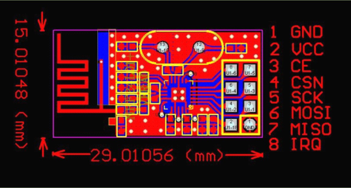
NRF24L01 Layout and Pins (Source: GitHub)
Module Schematics:
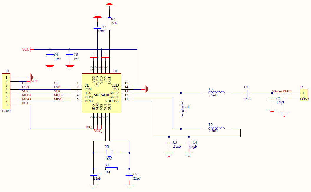
nRF24L01 Schematic (Source: GitHub)
Block Diagram of nRF24L01+:
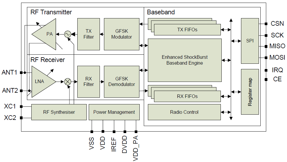
nRF24L01 Block Diagram (Source: Nordic Semiconductor Data Sheet nRF24L01P_Product_Specification_1_0.pdf)
Pin and SPI Connection
The module has following pins connecting to a microcontroller:
- GND: Ground.
- VCC: 3.3V.
- CE: Chip (RX/TX) Enable, high active. If high, module is either sending or listening.
- CSN: Chip Select Not, low active. If low, the chip responds to SPI commands. This is actually the ‘real’ chip select signal, and is easily confusing with CE which enables/disables the transceiver radio part.
- SCK: SPI Shift Clock, up to 10 MHz.
- MOSI: Master-Out-Slave-In, used to shift data from the microcontroller to the device.
- MISO: Master-In-Slave-Out, used to shift data from the device to the microcontroller.
- IRQ: Optional Interrupt Request pin. Signals RX/TX status like packet sent or received.
Bit/Byte order: The SPI needs to be configured to send the Most Significant Bit First. within a byte. For multiple data bytes, the Least Significant Byte needs to be shifted first.
Sender and Receiver Application
Time to get some hands-on! For this I’m using two RF modules with two FRDM-KL25Z. One board is sending data to the other, and they indicate with LED blinking proper operation. I’m using interrupts, but to keep things simple, I will only set a flag in the ISR I will do the radio processing outside of the interrupt service routine.
💡 Just setting a flag in the ISR keeps the interrupt service routine short and sweet, and I do not block further interrupts by accessing the radio module over the SPI bus. Additionally I use the SPI bus with interrupts, so doing interrupt-based SPI within another interrupt needs careful interrupt level planning. To keep things simple, I will not do this here.
Hardware Wiring
First, I need to wire the RF module to the processor. I’m using Processor Expert with CodeWarrior as this simplifies a lot. In this tutorial I’m using the following pin mapping:
=================================================================
 SIGNAL LIST
-----------------------------------------------------------------
SIGNAL-NAME [DIR]        => PIN-NAME [PIN-NUMBER]
-----------------------------------------------------------------
LED_BLUE [Output]        => ADC0_SE5b/PTD1/SPI0_SCK/TPM0_CH1 [74]
LED_GREEN [Output]       => TSI0_CH12/PTB19/TPM2_CH1 [54]
LED_RED [Output]         => TSI0_CH11/PTB18/TPM2_CH0 [53]
RF_CE [Output]           => PTB9 [48]
RF_CSN [Output]          => PTB8/EXTRG_IN [47]
RF_IRQ [Input]           => PTD0/SPI0_PCS0/TPM0_CH0 [73]
RF_MISO [Input]          => PTE3/SPI1_MISO/SPI1_MOSI [4]
RF_MOSI [Output]         => ADC0_SE7b/PTD6/LLWU_P15/SPI1_MOSI/UART0_RX/SPI1_MISO [79]
RF_SCK [Output]          => PTE2/SPI1_SCK [3]
=================================================================
- Make sure you have any extra components loaded (e.g. Wait and LED, see here).
- Create a Processor Expert project with the wizard (File > New Bareboard Project), then select your CPU and enable Processor Expert.
- Add the Wait component to your project. It is optional, and I’m using it in the demo application to wait for a given number of milli-seconds. Alternatively you can burn cycles in a loop.
- Add LED components to your project as needed (see this post). I’m using them to indicate the TX and RX status. Alternatively you can use BitIO component instead, or left it out.
- Now I’m going to add the components for the hardware connection to the module. If you are going to use different pins, then assign different pin names (of course).
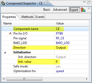
- Add a BitIO component for CE: It is configured as output pin with initial LOW value. LOW means ‘not sending/listening’, so this is a good initialization value.

CE Properties
- Add a BitIO component for CSN: It is configured as output pin with initial HIGH value. CSN is pulled LOW to send commands to the transceiver.

CSN Properties
- Add an ExtInt component for the interrupt pin: The interrupt is active low, so we need to react on falling edge:
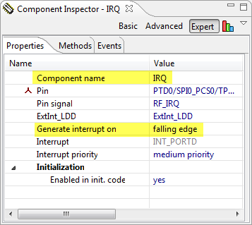
IRQ Properties
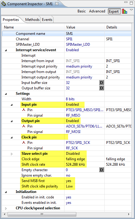
- Next to add SynchroMaster component for SPI:I need to assign the MISO, MOSI and CLK pins. Clock edge is on falling edge with MSB first, with LOW idle clock state. I’m using a fairly slow clock speed for now (it could go up to 10 MHz, but better to start slowly :-))

SPI Properties


💡 In above settings I have configured an Input and Output buffer size. This would allow me to send data in blocks. To keep things simple, I will send in this tutorial the data to the SPI character by character. Not ideal from a performance point of view, but again: we keep things simple. Once things are working, it is time to optimize things.
For me it looks now like this:
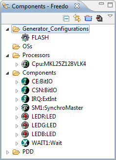
Project with components
Source Files
With File > New > Source File and File New > Header File I’m adding
- Application.c: this is the application main file
- Application.h as interface for Application.c
- nRF24L01.c: Driver for the Transceiver
- nRF24L01.h interface to nRF24L01.c
The content of the files are posted at the end of this article. I’m explaining now what needs to be done to send and receive data. What is common is the initialization code.
Initialization
First, the application initilizes the driver and calls RF_Init():
WAIT1_Waitms(100); /* give device time to power up */ RF_Init(); /* set CE and CSN to initialization value */Actually, it only sets the CE and CSN pins:
/*! * \brief Initializes the transceiver. */ void RF_Init(void) { RF_CE_LOW(); /* CE high: do not send or receive data */ RF_CSN_HIGH(); /* CSN low: not sending commands to the device */ }Next, it writes to configures the device using
RF_WriteRegister(), configuring the output power (RF24_RF_SETUP_RF_PWR_0) and configures the data rate (250 kbit,RF24_RF_SETUP_RF_DR_250):RF_WriteRegister(RF24_RF_SETUP, RF24_RF_SETUP_RF_PWR_0|RF24_RF_SETUP_RF_DR_250);It is using the RF_SETUP (address 0x06) register:
| Address (Hex) | Mnemonic | Bit | Reset Value | Type | Description |
|---|---|---|---|---|---|
|
06
|
RF_SETUP
|
RF Setup Register | |||
|
CONT_WAVE
|
7
|
0
|
R/W | Enables continuous carrier transmit when high. | |
|
Reserved
|
6
|
0
|
R/W | Only ‘0’ allowed | |
|
RF_DR_LOW
|
5
|
0
|
R/W | Set RF Data Rate to 250kbps. See RF_DR_HIGHfor encoding. | |
|
PLL_LOCK
|
4
|
0
|
R/W | Force PLL lock signal. Only used in test | |
| RF_DR_HIGH | 3 |
1
|
R/W | Select between the high speed data rates. This bitis don’t care if RF_DR_LOW is set.Encoding:[RF_DR_LOW, RF_DR_HIGH]:‘00’ – 1Mbps‘01’ – 2Mbps‘10’ – 250kbps‘11’ – Reserved | |
|
RF_PWR
|
2:1
|
11
|
R/W | Set RF output power in TX mode’00’ – -18dBm’01’ – -12dBm’10’ – -6dBm’11’ – 0dBm | |
|
Obsolete
|
0
|
Don’t care |
I’m using a method RF_WriteRegister() which writes a register on the transceiver:
void RF_WriteRegister(uint8_t reg, uint8_t val) { /*! * \brief Write a register value to the transceiver * \param reg Register to write * \param val Value of the register to write */ void RF_WriteRegister(uint8_t reg, uint8_t val) { RF_CSN_LOW(); /* initiate command sequence */ (void)SPI_WriteRead(RF24_W_REGISTER|reg); /* write register command */ (void)SPI_WriteRead(val); /* write value */ RF_CSN_HIGH(); /* end command sequence */ RF_WAIT_US(10); /* insert a delay until next command */ }The program uses several macros to hide low-level functionality for portability:
/* Macros to hide low level functionality */ #define RF_WAIT_US(x) WAIT1_Waitus(x) /* wait for the given number of micro-seconds */ #define RF_WAIT_MS(x) WAIT1_Waitms(x) /* wait for the given number of milli-seconds */ #define RF_CE_LOW() CE_ClrVal() /* put CE LOW */ #define RF_CE_HIGH() CE_SetVal() /* put CE HIGH */ #define RF_CSN_LOW() CSN_ClrVal() /* put CSN LOW */ #define RF_CSN_HIGH() CSN_SetVal() /* put CSN HIGH */I’m using the following method to write (and read from) the SPI:
/*! * \brief Writes a byte and reads the value * \param val Value to write. This value will be shifted out * \return The value shifted in */ static uint8_t SPI_WriteRead(uint8_t val) { uint8_t ch; while (SM1_GetCharsInTxBuf()!=0) {} /* wait until tx is empty */ while (SM1_SendChar(val)!=ERR_OK) {} /* send character */ while (SM1_GetCharsInTxBuf()!=0) {} /* wait until data has been sent */ while (SM1_GetCharsInRxBuf()==0) {} /* wait until we receive data */ while (SM1_RecvChar(&ch)!=ERR_OK) {} /* get data */ return ch; }The code uses
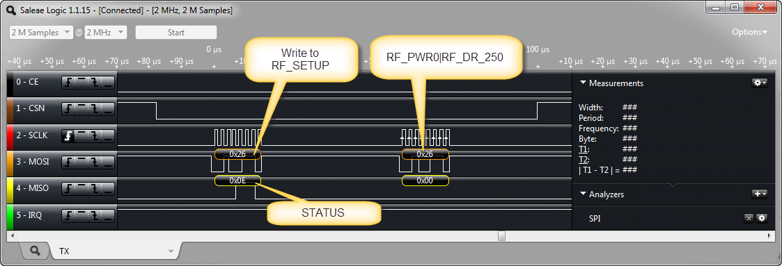
RF24_W_REGISTER(0x20) which is used to mark a ‘write’ command. TheRF_SETUPregister is 0x06, so together this build the value0x26on the bus.RF24_RF_SETUP_RF_PWR_0|RF24_RF_SETUP_RF_DR_250together build as well the value0x26. So what is sent over the bus is this:RF_SETUP Write
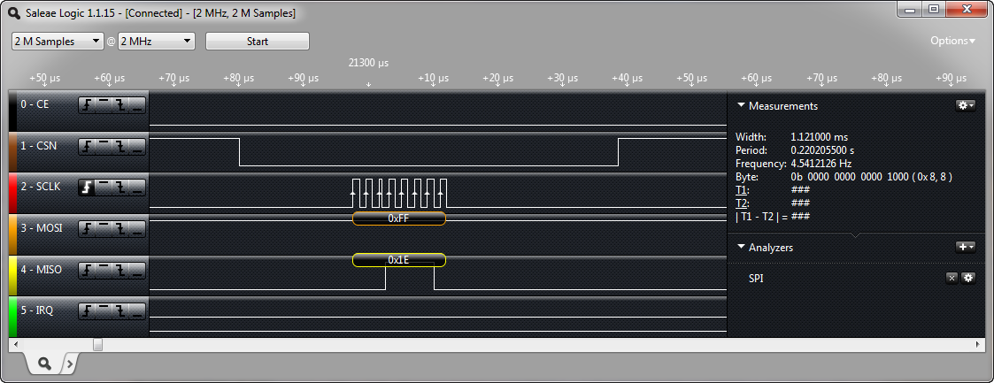
As you can see, the transceiver always responds with the STATUS byte. This status can be polled with a NOP command too. This is implemented with
/*! * \brief Read and return the STATUS * \return Status */ uint8_t RF_GetStatus(void) { return RF_WriteRead(RF24_NOP); }On the bus this looks like this:
NOP (0xff) command to get STATUS register
Payload
Next, I configure the payload (amount of data transmitted). It is possible to use variable payload, but in my example I’m using a fixed size wich is defined in the
PAYLOAD_SIZEmacro. Payload size is configured with register 0x11 (RX_PW_P0) for communication channel 0 (I going to use only one communication channel):RF_WriteRegister(RF24_RX_PW_P0, PAYLOAD_SIZE); /* number of payload bytes we want to send and receive */Channel
And then I configure it to use the RF channel (macro
CHANNEL_NO):RF_WriteRegister(RF24_RF_CH, CHANNEL_NO); /* set channel */RX and TX Address with address matching
In need to assign an address for the TX and RX channels, and enable address matching:
static const uint8_t TADDR[5] = {0x11, 0x22, 0x33, 0x44, 0x55}; /* device address */ /* Set RADDR and TADDR as the transmit address since we also enable auto acknowledgment */ RF_WriteRegisterData(RF24_RX_ADDR_P0, (uint8_t*)TADDR, sizeof(TADDR)); RF_WriteRegisterData(RF24_TX_ADDR, (uint8_t*)TADDR, sizeof(TADDR)); /* Enable RX_ADDR_P0 address matching */ RF_WriteRegister(RF24_EN_RXADDR, RF24_EN_RXADDR_ERX_P0); /* enable data pipe 0 */Sender or Receiver
So far the initialization code is the same for sender and receiver. Now things are bit different, distinguished by the macro IS_SENDER which I use locally in my application:
#if IS_SENDER RF_WriteRegister(RF24_EN_AA, RF24_EN_AA_ENAA_P0); /* enable auto acknowledge. RX_ADDR_P0 needs to be equal to TX_ADDR! */ RF_WriteRegister(RF24_SETUP_RETR, RF24_SETUP_RETR_ARD_750|RF24_SETUP_RETR_ARC_15); /* Important: need 750 us delay between every retry */ TX_POWERUP(); /* Power up in transmitting mode */ CE_ClrVal(); /* Will pulse this later to send data */ #else RX_POWERUP(); /* Power up in receiving mode */ CE_SetVal(); /* Listening for packets */ #endifI’m going to use ‘auto acknowledge’: with this, the sender will transparently handle an acknowledge. For this I need to configure the retry time if communication fails for 750 μs and 15 retries.
Next, two macros are used:
/* macros to configure device either for RX or TX operation */ #define TX_POWERUP() RF_WriteRegister(RF24_CONFIG, RF24_EN_CRC|RF24_CRCO|RF24_PWR_UP|RF24_PRIM_TX) /* enable 2 byte CRC, power up and set as PTX */ #define RX_POWERUP() RF_WriteRegister(RF24_CONFIG, RF24_EN_CRC|RF24_CRCO|RF24_PWR_UP|RF24_PRIM_RX) /* enable 2 byte CRC, power up and set as PRX */Both macros write the
CONFIGregister: it enables CRC (EN_CRC) with 2 byte CRC (CRCO), powers up the transceiver (PWR_UP). The only difference between sender and receiver is thePRIM_TXflag which tells the configuration register to be the sender.Below are the details about the
CONFIGregister:CONFIG Register (Source: nRF24L01P Data Sheet)
❗ Note that there are 3 ‘interrupt mask’ or ‘interrupt inhibit’ bits. I’m intentionally *not* setting these bits because I want to use interrupts (more later).
The last part is to set the CE pin either low or high: setting it HIGH will let the receiver start listening. The CE pin is set high on the sender to initiate sending the data.
Status Register
The transceiver is having 3 bits in the status register to tell
- if data transmission was successful
- if data has been received
- if sending was not possible (maximum retry reached)
Before going actually to send/receive, I’m going to reset the 3 bits with the following routine:
RF_ResetStatusIRQ(RF24_STATUS_RX_DR|RF24_STATUS_TX_DS|RF24_STATUS_MAX_RT);which is implemented as
/*! * \brief Reset the given mask of status bits * \param flags Flags, one or more of RF24_STATUS_RX_DR, RF24_STATUS_TX_DS, RF24_STATUS_MAX_RT */ void RF_ResetStatusIRQ(uint8_t flags) { RF_WAIT_US(10); RF_CSN_LOW(); RF_WAIT_US(10); RF_WriteRegister(RF24_STATUS, flags); /* reset all IRQ in status register */ RF_WAIT_US(10); RF_CSN_HIGH(); RF_WAIT_US(10); }With this, we are ready to send and receive data :-).
Sending the Data
Sending data is performed by
RF_TxPayload(payload, sizeof(payload)); /* send data */which is implemented as:
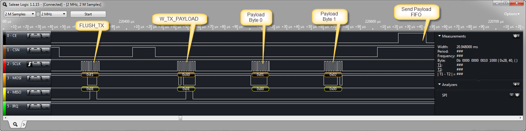
/*! * \brief Send the payload to the Tx FIFO and send it * \param payload Buffer with payload to send * \param payloadSize Size of payload buffer */ void RF_TxPayload(uint8_t *payload, uint8_t payloadSize) { RF_Write(RF24_FLUSH_TX); /* flush old data */ RF_WriteRegisterData(RF24_W_TX_PAYLOAD, payload, payloadSize); /* write payload */ RF_CE_HIGH(); /* start transmission */ RF_WAIT_US(15); /* keep signal high for 15 micro-seconds */ RF_CE_LOW(); /* back to normal */ }What it does is first flushing the TX FIFO with writing to the
FLUSH_TXregister, just in case there is still something in there). Then it writes the payload data withW_TX_PAYLOAD.❗ The number of bytes transmitted as payload needs to be the number of payload bytes specified above with the write the
RX_PW_P0register!Finally it sends a pulse with the CE pin of at least 15 μs to initiate the sending of the data over the air.
W_TX_PAYLOAD command with Flush
Interrupts
As pointed out above, I’m not setting the interrupt mask bits in the
CONFIGregister. In my application, I route the interrupts to the following handler, both for the sender and receiver:static volatile bool isrFlag; /* flag set by ISR */ void APP_OnInterrupt(void) { CE_ClrVal(); /* stop sending/listening */ isrFlag = TRUE; }I’m only setting a flag in the interrupt routine and pulling CE low to stop listening (if I’m listening). That function is called from Events.c:
/* ** =================================================================== ** Event : IRQ_OnInterrupt (module Events) ** ** Component : IRQ [ExtInt] ** Description : ** This event is called when an active signal edge/level has ** occurred. ** Parameters : None ** Returns : Nothing ** =================================================================== */ void IRQ_OnInterrupt(void) { APP_OnInterrupt(); }Inside my sender main loop, I’m checking that interrupt flag and reset the STATUS flags as needed:
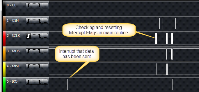
if (isrFlag) { /* check if we have received an interrupt */ isrFlag = FALSE; /* reset interrupt flag */ status = RF_GetStatus(); if (status&RF24_STATUS_RX_DR) { /* data received interrupt */ RF_ResetStatusIRQ(RF24_STATUS_RX_DR); /* clear bit */ } if (status&RF24_STATUS_TX_DS) { /* data sent interrupt */ cntr = 0; /* reset timeout counter */ LEDR_Off(); /* indicate data has been sent */ RF_ResetStatusIRQ(RF24_STATUS_TX_DS); /* clear bit */ } if (status&RF24_STATUS_MAX_RT) { /* retry timeout interrupt */ RF_ResetStatusIRQ(RF24_STATUS_MAX_RT); /* clear bit */ } }This then looks like this:
Interrupt after data has been sent
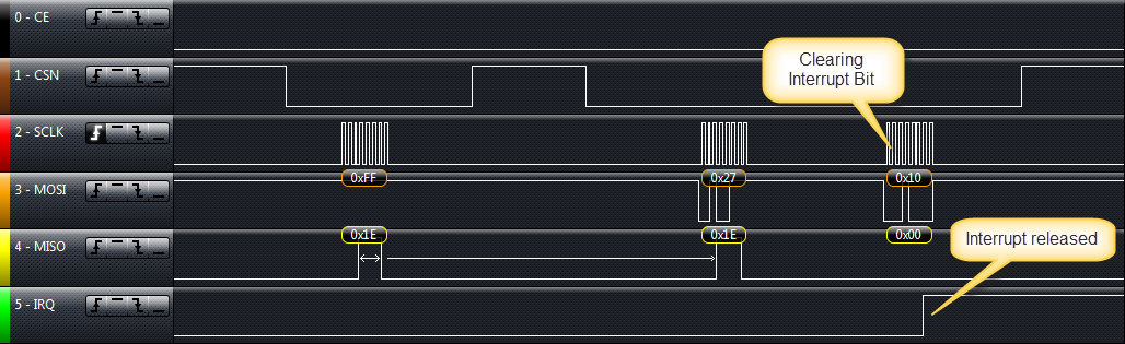
Resetting the interrupt bit is needed to get the IRQ line back to HIGH. The zoom below shows that sequence in more details: It queries the status (0xFF instruction) which returns 0x1E (max retry reached, all FIFOs empty). Then it uses 0x27 command to reset the 0x10 bit.
Resetting Interrupt Flag
If data has been sent and acknowledge received, the 0x20 bit is set:
Interrupt with successful data sent
Receiver
Things are very similar on the receiver side: I check if an interrupt occured, then checking the flags. If the
STATUS_RX_DRbit is set, it reads the data withRxPayload():if (isrFlag) { /* interrupt? */ isrFlag = FALSE; /* reset interrupt flag */ cntr = 0; /* reset counter */ LEDB_Off(); LEDG_Neg(); /* blink green LED to indicate good communication */ status = RF_GetStatus(); if (status&RF24_STATUS_RX_DR) { /* data received interrupt */ RF_RxPayload(payload, sizeof(payload)); /* will reset RX_DR bit */ RF_ResetStatusIRQ(RF24_STATUS_RX_DR|RF24_STATUS_TX_DS|RF24_STATUS_MAX_RT); /* make sure we reset all flags. Need to have the pipe number too */ } if (status&RF24_STATUS_TX_DS) { /* data sent interrupt */ RF_ResetStatusIRQ(RF24_STATUS_TX_DS); /* clear bit */ } if (status&RF24_STATUS_MAX_RT) { /* retry timeout interrupt */ RF_ResetStatusIRQ(RF24_STATUS_MAX_RT); /* clear bit */ } } else { cntr++; if (cntr>500) { /* blink every 500 ms if not receiving data */ cntr = 0; /* reset counter */ LEDG_Off(); LEDB_Neg(); /* blink blue to indicate no communication */ } WAIT1_Waitms(1); /* burning some cycles here */ }The receiver routine is similar to the sender one:
/*! * \brief Receive the Rx payload from the FIFO and stores it in a buffer. * \param payload Pointer to the payload buffer * \param payloadSize Size of the payload buffer */ void RF_RxPayload(uint8_t *payload, uint8_t payloadSize) { RF_CE_LOW(); /* need to disable rx mode during reading RX data */ RF_ReadRegisterData(RF24_R_RX_PAYLOAD, payload, payloadSize); /* rx payload */ RF_CE_HIGH(); /* re-enable rx mode */ }It is using a method which reads the multiple payload bytes:
/*! * \brief Read multiple bytes from the bus. * \param reg Register address * \param buf Buffer where to write the data * \param bufSize Buffer size in bytes */ void RF_ReadRegisterData(uint8_t reg, uint8_t *buf, uint8_t bufSize) { RF_CSN_LOW(); (void)SPI_WriteRead(RF24_R_REGISTER|reg); SPI_WriteReadBuffer(buf, buf, bufSize); RF_CSN_HIGH(); RF_WAIT_US(10); }That’s it :-).
With this I’m able to send and receive data.
Source Code
The source code of this application is available on GitHub here.
Summary
This tutorial does not cover all the powerful aspects of the nRF24L01+, but should get you up and running quickly. I plan to add more functionality in the future and to create a dedicated Processor Expert component for this RF chip. Until then, I hope this tutorial is useful for you.
Happy Communicating 🙂


Thanks for all your help. And thanks for the credit! lol.
I am always learning with your amazing blog!
LikeLike
You are more than welcome. And thanks again for the tip to that wireless transceiver module.
LikeLike
Hi Erich,
Have you seen this? http://maniacbug.github.io/RF24Network/index.html
I dont know how far your project is going so maybe can be helpful for future implementations.
This week i will play with my FRDMs and the nrf24L01+
LikeLike
Hi Alex,
yes, I have seen this. But this is implemented in C++ which is less than ideal, and it is using a GPL version of licensing, which is very restrictive and not user friendly in my view. Of course you are open to use it, but especially because of the licensing terms I will not use it for my projects.
LikeLike
Thanks for this great blog!!!
LikeLike
thanks! I was looking for something like this for myself too 😉
LikeLike
Glad to see you got some tranceivers up and running!!
LikeLike
Yes, it was not that difficult with the help of a logic analyzer. Only the interrupt mode was tricky, as most examples and drivers I have found on the internet actually do not use it. Still I need to work on a dedicated Processor Expert component for the transceiver to make things even easier.
LikeLike
Pingback: Kinetis ARM Cortex M4 DIY Board for $5 | MCU on Eclipse
Pingback: Mini Sumo Robot Competition running with FRDM-KL25Z | MCU on Eclipse
Pingback: Zumo Robot Chassis PCB arrived! | MCU on Eclipse
Pingback: Zumo Robot assembled | MCU on Eclipse
Pingback: Tutorial: Using the FRDM-KL25Z as Low Power Board | MCU on Eclipse
thanks again! for that great work. I have a question how can the module be a sender and a receiver in the same time? do you have to create some algorithm to make one listen and other reply?
LikeLike
Hi Mauricio,
the transceiver cannot send and receive at the *same* time, but it can send something and then immediately switch to listen/receiving mode. In my demo application of this post I have one transceiver just sending and the other just receiving. But of course I’m using the nRF24L01+ both in send/receive mode in other project (half-duplex).
LikeLike
Thanks Again!
LikeLike
Hi Erich,
Do you have a half-duplex sketch with Auto Ack?
I would be glad to see it.
Thanks,
Mantico
LikeLike
Hi Mantico,
wireless transceivers typically are half-duplex 😉
Have you seen my example project in https://github.com/ErichStyger/mcuoneclipse/tree/master/Examples/CodeWarrior/FRDM-KL25Z/Freedom_NRF24L01
?
It is using auto-ack.
LikeLike
I checked your script and it looks like you have enabled autoack and interrupts, looks great!
However, I’m looking for a script that is able to transmit and receive during runtime. Your script is not able to do that. I think yours is prepocessor based on the #define is_sender statement.
Please correct me if I’m wrong.
LikeLike
Yes, I have that, but I have not put it on GitHub yet. It includes a simple network stack with all the layerings.
LikeLike
I’d be very interested to see it when it becomes available. I’ve searched the web and havent found a script that does bidirectional, peer to peer with autoack functionality working. I tried to create one but I’m stuck with the pipe0 issue. 😦
LikeLike
Hi Mantico,
I have started posting things on GitHub (https://github.com/ErichStyger/mcuoneclipse/tree/master/Examples/RNet). Very rough stuff, and again: work in progress. But maybe this gives you an idea where it is going. I’m working on a simple demo project too.
LikeLike
Hello Erich, Thanks you for this tutorial. It was really helpful.
I want to now something, how do you do to make it?, I mean understand the devices and make a source code.
Note: I’m a newbie, I really interested in learn how to develop, but I dont know where to begin.
LikeLike
Not sure what you have in mind? What do you want to do? If it is about learning to develop applications: always good to start with something small and simple, and then grow it.
LikeLike
What I have in mind, It’s develop on zigbee System. I’ll be working on a project that involved the HC08 (MC9S08QE128) and the MC1320. Well,I need to understand the device, but I don’t know where to begin or went implement a code or went implement event or interrupt. I think that is my biggest hole in knowledge events and interrupts.
Thank you again.
LikeLike
I’m using the MC1320x in my designs too. Not as ZigBee, but as normal wireless transceiver:
LikeLike
Hello
I am very enjoy to have found your web pages
I am Involved in building automation and home automation.
My project is visible on speranto.fr (french website).
For this project i am starting with Freescale KINETIS (Board FRDM-K20D50M ).
My PLC Will communicate with three support (for now)
1) 2.4Ghz radio with Nordic nFR24L01P + (NRF24LE1 is more powerfull he have UART serial interface).
2) Twisted Pair RS485
3) Encapsulation bus frame inside TCP / IP packets with the Microchip ENC28J60 circuit (which is very cheap, and drived by SPI)
For nFR24L01P + you have already done a lot of work and it will save me time.
For RS485, it should not pose much problem.
For the ENC28J60 circuit I looking if someone has already write code for a KINETIS Freescale.
Yet all my congratulations for the quality of your explanations.
Best regards
Yves Accard
LikeLike
Hi Yves,
glad to hear that things are helpful for you :-). I planned something similar, but instead of using that ENC28J60, I was looking at the W5500 (http://www.wiznet.co.kr/en/product/Product_Detail.asp?cate1=5&cate2=7&cate3=77&pid=1193) which is used in many projects. Any special reasons why you would use that ENC28J60?
Erich
LikeLike
Hello
Thank you very much for your message.
I chose the ENC28J60 because it is the first one I found.
It has existed since 2004 and it is easy to find code “ready to use” (for ATMEGA or MICROCHIP).
It is easy to find some electronics boards “ready to use”.
There is also the 244J600, a little more expensive but is a 10/100 Base-T (ENC28J60 is a 10 Base-T).
In addition, 244J600 may be interfaced in serial mode (and SPI also).
I watched the W5500 WIZNET, it is 10/100 Base-T , drived by SPI and the price is the same as 244J600.
I have found only a very little number of electronics boards “ready to use” for use with W5500 (on INTERNET).
But I find a lot of electronic boards with this component WIZNET W5100 (for Arduino).
The WIZNET chipset W5100 is quite expensive (5 dollards!).
In summary, the WIZNET W5500 is more powerful and almost the same price as ENC28J60.
I am ready to use the W5500 if someone develops some code that I could easily reuse.
Because I have more expertise in hardware than software .
Again thank you.
Yves Accard
Onebus
LikeLike
Hello
Perhaps this WEB page (French but write in English) will help you.
http://myfreescalewebpage.free.fr/theuno/appnote_webserver/appnote_webserver.htm
He use the W5100
Best regards
Yves Accard
Onebus
LikeLike
Hi Erich, great tutorial thanks. I’m just wondering if all of this sample code will work without the use of the logic analyser that you have used?
LikeLike
Hi David,
yes, a logic analyzer is not needed. I only used it to illustrate the signals. But in any case, I recommend a logic analyzer as a tool for every engineer working with hardware: without it, it will be very hard to isolate and solve communication problems with external hardware.
LikeLike
Pingback: RNet: optional ACK, Dynamic Payload and Extended nRF24L0+ Driver | MCU on Eclipse
may you please tell me do this transceiver be interfaced with mobile’s bluetooth if not is there any low power module which do so ?
LikeLike
This module does not interface with anything else then the nRF24L01.
LikeLike
i need a low power bluetooth module, which can be interfaced with my
mobile bluetooth….not a regular bluetooth.
and please give me link where i can get that.
LikeLike
nRF24L01+ Transceiver Module -FREE ISM Band
LikeLike
hey is there any a low power bluetooth module having range upto 50 meters, which can be interfaced with my mobile bluetooth.
and please give me link where i can get that.
LikeLike
I would say the answer is ‘yes’ (at least I presume so). But I don’t have one or use one.
LikeLike
ok which bluetooth you know of maximum range with low power usage ?
and may you please give me the link.
LikeLike
sir may you please suggest me a best low power bluetooth module with maximum range (i.e 50 meters or near by) available.
LikeLike
Hello,
50 meters will be very challenging with normal antennas or normal modules availble. I suggest that you make a research and do a comparison of different modules and measure things with a professional equipment. ‘Best low power’ is not a simple thing to evaluate: it will depend on usage, transmittion patterns and even software drivers used. To the end, you need to do your own research on this. I think nobody will be able to provide you a link or a definitive answer.
LikeLike
Hi Erich,
Thanks for referring me to this tutorial =) ! I will give it a try.
Here’s the IMU that I’m using, just in case if you’re interested: http://www.analog.com/static/imported-files/data_sheets/ADIS16360_16365.pdf.
Thanks for your great work!
Dao.
LikeLike
Pingback: IoT: FreeRTOS Down to the Micro Amps | MCU on Eclipse
your tutorial helped me in understanding RF24L01. kindly tell me that if we want to create a two way communication between RF then we will uSE the same 8 pins of RF at both ends or their will any change ? basically i want create communication between PIC microcontroller and PC through RF 24L01 , but i dnt know what will be the interfacing circuits between PIC and RF at one end and between RF and PC at the other end … ? kindly help me out
LikeLike
It should be fairly easy to use the nRF24L01+ with your PIC. But on the PC side that will be different, as your PC (windows? Linux?) is not an ideal system for interfacing with such a module. What we did is using it with a Raspberry Pi, and that worked pretty well 🙂
LikeLike
Hello Erich, I have too boards one i config as a Sender and other a receiver. But for sure they arent communicating to each other, because the receiver is just blinking blue.
How can i debug that?
thanks
LikeLike
Hi Mauricio,
first, check that the wires are correctly wired. Then check with the debugger in the radio.c what you are receiving?
LikeLike
After Corrected the wires worked! Mein Got! Thanks for all the help.
LikeLike
It is always about the basics 😉 Good to hear that things are working now for you. You might check out my other articles where I developed a wireless network stack for it: https://mcuoneclipse.com/2013/11/17/rnet-a-simple-open-source-radio-network-stack/
Things are still basic, but at least for me it does what I need.
LikeLike
Great tutorial. Educative and helpfull. I do have a question: is it possible to connect nRF24L01+ (or other) with regular Access Point (with WPA or other protection) on 2.4 GHz? nRF24L01+ would be only transmitter.
LikeLike
No, this is not possible. The nRF24L01+ is not WiFi, even if using the same band: the modulation and the frequencies are different.
LikeLike
Thank you for prompt answer. I’ve assumed. Do you know some low cost module that could achieve that?
LikeLike
Have a look at the Adafruit CC3300 WiFi module: https://www.adafruit.com/products/1469
LikeLike
Will do. Thanks 😉
LikeLike
Hello and thanks to every one, I started a new project for wireless object locator (without RFID) using PIC18F452 Microcontroller. what is the best transceiver to use ? I need 4 units to stick them to objects and just to send some signal replaying to some polling mechanism and also to generate alarm when objects are out of some rang. thanks again.
LikeLike
It all depends on your requirements (distance? power consumption? interfacing to other systems? which wireless band to use?).
LikeLike
Thanks Erich, well, what I need is a microcontroller-based system within an office or house that locates objects by emitting light and sound signal when they are lost and also warns when these objects go out the building.
LikeLike
Thanks Erich, well, what I need is a microcontroller-based system within an office or house that locates objects by emitting light and sound signal when they are lost and also warns when these objects go out the building.
LikeLike
A FRDM-KL25Z with an nRF24L01+ sound like a good solutions to me for this.
LikeLike
thank you very much Erich . I ‘ll check.
LikeLike
Pingback: Enhanced RNet Wireless Components and Communication Stack | MCU on Eclipse
Pingback: Tutorial: Nordic Semiconductor nRF24L01+ with the Freescale FRDM-K64F Board | MCU on Eclipse
Pingback: Zumo Robot with WiFi and GPS | MCU on Eclipse
Pingback: NeoShield: WS2812 RGB LED Shield with DMA and nRF24L01+ | MCU on Eclipse
Hi Eric
#define TX_POWERUP() RF_WriteRegister(RF24_CONFIG, RF24_EN_CRC|RF24_CRCO|RF24_PWR_UP|RF24_PRIM_TX) /* enable 1 byte CRC, power up and set as PTX */
I believe that the comment is incorrect here since the code is setting 2 bytes CRC.
This has led to some confusion as discussed,
Regards
Mark
LikeLike
Hi Marc,
good catch! Yes, setting that CRCO bit means two byte CRC. I have fixed it in the post.
Thanks!
Erich
LikeLike
Hey Styger, we’ve tried this code between a KL25z and a KL46z for an university project, and we can’t get any data to transfer. As far as we can tell, it is not an SPI issue, because we can write a value and then read it. We also concluded it is not a hardware issue, because we had the transcievers working with two Arduinos.
We’ve been going aroud this for days. We’ve tested all your examples, including your RNet (https://mcuoneclipse.com/2013/11/17/rnet-a-simple-open-source-radio-network-stack/), RNet simple, carefully following each and every step. We’ve even ported the working Arduino library with no success.
Could this be because of some configuration on the KL46z we’re missing? Do you have any suggestions? We would really appreciate your help. We are on the verge of going cuckoo.
LikeLike
Hey Erich, we’ve tried this code between a KL25z and a KL46z for an university project, and we can’t get any data to transfer. As far as we can tell, it is not an SPI issue, because we can write a value and then read it. We also concluded it is not a hardware issue, because we had the transcievers working with two Arduinos.
We’ve been going aroud this for days. We’ve tested all your examples, including your RNet (https://mcuoneclipse.com/2013/11/17/rnet-a-simple-open-source-radio-network-stack/), RNet simple, carefully following each and every step. We’ve even ported the working Arduino library with no success.
Could this be because of some configuration on the KL46z we’re missing? Do you have any suggestions? We would really appreciate your help. We are on the verge of going cuckoo.
LikeLike
Can you check the SPI signals with a logic analyzer if they are correct? Check all the data/command lines to the receiver. Then you probably see the problem (I hope).
LikeLike
I’ve tested the SPI sending the NOP and I didn’t receive the 0x0e UNTIL I connected the RF VCC and GND to an external power supply. What I mean is that the spi didn’t work when drawing current from the 3V3 freedom board output. It’s really weird, because the module doesn’t need that much juice.
However, the transmission doesn’t work. Well, to tell you the truth we’ve received several packets twice. But closing the debugger and opening it up again gave us no good results. Without changing anything at all, the transmission was again unsuccessful. I guess this fact makes the situation even more puzzling.
We have not had access to a logic analyzer yet, but will, tomorrow. We will let you know what’s the outcome.
LikeLike
Interesting finding. But it matches a problem I had faced with a few modules, that they draw too much current. I believe the problem is with bad nRF24L01+ modules, I remember even a post in the Nordic forums about this: it seems to be possible to ‘misconfigure’ the internal memory of the device so it does not go into low power sleep mode.
The other thing to keep in mind: some older FRDM boards have a voltage drop on the 3.3V regulator, see https://mcuoneclipse.com/2013/05/12/fix-for-3-3v-voltage-drop-on-frdm-kl25z-board/
I recommend you exchange the modules.
LikeLike
Great! I was getting 2V9 from the 3V3 output. I bypassed the diode and now I can power the module from the KL25Z.
However, we are still unable to get reliable data transmission. I will test with other modules, for the sake of it.
Unuckily, we weren’t able to get our hands on the logic analyzer, which is a pitty. I hope we’re luckier tomorrow.
LikeLike
Now we’ve tried your RNet example with the console. In this case, running without the debugger we’re unable to successfully make a transmission. On one side we “send” and we don’t get any lost packets in the status. On the other board when we try sending we get “ERR timeout”. The exact same behaviour we got with the debugger.
LikeLike
Hi
I am assuming that you have Freedom boards – if that is the case you can try running the binaries from
http://www.utasker.com/kinetis/FRDM-KL25Z.html
and
http://www.utasker.com/kinetis/FRDM-KL46Z.html
(at the bottom of each page)
These allow the KL25Z to be primary transmitter and it will poll slaves. The KL46Z slave will responds with a slightly modified version of the polling message.
The connections are detailed there – as long as the transceiver is correctly detected there are further messages on the UART informing of ACKs or lost data.
Regards
Mark
LikeLike
We’re running this code now. We’ve just realized that it ALWAYS works (led turns green as soon as the receiver is plugged) when we connect the boards and it just runs. But if we run it from the debugger it doesn’t! What can this be?!
LikeLike
Hi,
I try to use MKL05 uP with nrf24l01 in LowPower application. When i add nrf componet from component library to components, the power consumption in DOM_STOP cpu operation mode, growing to 0,78mA (even when disconnect nrf module and don’t use RF1). Wen I remove nrf componet (with subcomponents) power consumption return to ~1.8µA
I tried to disabled SPI but without success.
LikeLike
There are to things: disabling the SPI (clock gating) and avoid that the microcontroller is feeding the nRF with the SPI lines. Maybe this is the problem that there is current flowing from the SPI lines to the nRF module which then draws the current?
LikeLike
I’m curious if the transceiver guarantees reception of data as the hardware now exists? I.e. will it add error detection/correction bits and effect retransmission on error? Or do I need to code this up in software? There are separate devices that encode and decode for error work, as I understand. Do these devices draw data from and put it into buffers or must I detect byte sequence errors in software?
LikeLike
If you have CRC enabled in the transceiver, it will do its own CRC checking, so you might now want to add your own in your own protocol. And yes, if there is an error: the sender will not receive the ACK package, and then automatically resend it according to the device settings. So no need for you to detect sequence errors in your software, unless you want to ensure even higher data integrity.
LikeLike
Just another point: reception of the data is only guaranteed within the boundaries configured in the transceiver. E.g. the number of data sending repeats is limited. So you still want to implement a ‘retry’ functionality in your software. If you have a look at my RNet stack I’m using for the nRF24L01+, this is implemented in the network layer.
LikeLike
Thanks for both your replies. I understood them both.
As soon as you mentioned RNet, it dawned on me that these tasks are already done by WIFI devices. While the RF comms was likely fun to implement, I though a private wireless LAN was a ready made solution. Any opinions?
Just FYI: Devices became available in 2007; yourDuino still has the units for $2.45.
LikeLike
The problem with WiFi is that it is not really usable for battery operated devices: it is too complex and needs too much power. That’s why I’m using small and power optimized nodes like the nRF24L01+ as edge nodes.
LikeLike
Another thought: the issue with nRF24L01+ devices is that they do not support a broadcast mechanism: so they are not usabable for ad-hoc wireless networks.
LikeLike
Hi Eric,
Thank you for a very nice tutorial. I wonder if you have worked with nrf24le1. I am working on a module and can’t make it work although I have nrf24l01+ working. I ported the program from arduino to the nrf24le1 but no luck. I am a total newbie on 8051 mcu. I hope you can point me in the right direction if by chance, you have done work on an nfr24le1.
Best regards
Ramon
LikeLike
Hi Ramon,
no, I have no experience with the nRF24LE1 module at all. Good luck!
LikeLike
i have a problem with nrf.. module if i operate it with a 3volt isolated dc supply its working normal but if i operate it with LM 1117-3.3 ie 3.3 volt output IC it is not working.please help me
LikeLike
I guess your 3.3V is not stable. Any RF products are very sensitive on the supply voltage. Make sure it is rock solid.
LikeLike
Can it be used to connect two pc point to point for internet purpose.
LikeLike
Yes, but it depends. The nRF24L01+ is not talking normal WiFi, so cannot directly connect to your internet. But you can use it with a gateway.
LikeLike
For Wi-Fi purposes use ESP-8266.
LikeLike
Hi Eric,
I also take a two boards, one as receiving, another as sending.
But for sure they are not communicating to each other, because the two boards are just blinking blue.
I see you say the following sentence.
“first, check that the wires are correctly wired. Then check with the debugger in the radio.c what you are receiving?””
I think there is no problem wiring .
I can’t check with the debugger in the radio.c, because i can’t find radio.c in ur project.
How can I solve it . thanks.
LikeLike
Hi Jerry,
I’m sorry, that Radio.c is used in later versions of that project. In the project used in this post the functionality of Radio.c is in Application.c.
I assume you are using iterrupts, so set a breakpoint in IRQ_OnInterrupt() in Evetns.c which then should call APP_OnInterrupt(). If you do not get an interrupt if someone has sent a packet, then maybe your wiring/connection to the module is wrong?
I hope this helps,
Erich
LikeLiked by 1 person
Very nice tutorial, thank you!
LikeLike
I’m creating a series of posts on the nRF24 modules, using Arduino, Raspberry Pi or Particle Core/Photon. I would like to receive your feedback, at the moment I have 2 posts out of 7 out rlogiacco.wordpress.com/2015/09/06/nrf24-walk-through-introduction/.
LikeLike
Great series of articles, keep them going!
LikeLike
Pingback: Arduino ile Panjur Kontrolü | tetproject
Pingback: Kablosuz Ev Otomasyonu Cihazları | tetproject
Hello Erich,
Where could I find nRF24L01.c and nRF24L01.h? The link to GitHub gives a 404 error…
LikeLike
Hi Juanjo,
The structure on GitHub has changed a bit, and missed to update that link (fixed now): it is https://github.com/ErichStyger/mcuoneclipse/tree/master/Examples/CodeWarrior/FRDM-KL25Z/Freedom_NRF24L01
LikeLike
Hello Erich, I just began working with Freescale microcontrollers and I have a project to implement with the nRF24L01 module, and I don’t understand what you put on your main. I have the LEDs working but I don’t know what I need to add to the main routine. Could you help me please with some advises ? Regards
LikeLike
Hi Guillaume,
have a look at the example projects for nRF I have put on GitHub.
Keep in mind that they are using the RNet (https://mcuoneclipse.com/2013/11/17/rnet-a-simple-open-source-radio-network-stack/). For example see https://github.com/ErichStyger/mcuoneclipse/tree/master/Examples/KDS/FRDM-KL25Z/FRDM-KL25Z_Joystick.
Erich
LikeLike
Hello, Erich,
I understood a lot about the code but I don`t know how exactly connect the hardware (the senzors and the board). What do I need for making the hardware to work? Thank you!
LikeLike
For the nRF24L01+ you need a chip select, the MISO, MOSI and CLK (clock) lines. Plus optionally an interrupt line. And of course 3.3V plus GND for the power.
LikeLike
Hello Erich,
Your codes work very well !! Thank you for this very good tutorial. Do you think it is easy to connect the receiver to a LCD to receive on it a message sent from the transmetter ? Where in the Payload i have to put the message ? I don’t understand all the code but i work on it.
Thank you again for this very clear tutorial.
Maxime
LikeLike
Hi Maxime,
it is up to you how you format the payload message. The example in this article is very basic, so you can do whaterver you want.
If you want to use a more sophisticated stack, have a look at https://mcuoneclipse.com/2013/11/17/rnet-a-simple-open-source-radio-network-stack/.
After that article, I wrote a Processor Expert component for it to make it even easier.
LikeLike
I got another problem, i try to use the KL25Z32VFM4 with as a debugger the kl25Z. i cut the link at the right place on the kl25z to use it only as debugger. However i don’t succed to set well the CPU … a change pins as i should, but the debugger says that it has a problem with the CPU…
Any Idea ?
Error
Error 17926. Target Type MCU mismatch. Unexpected processor type detected. Aborting debug session.
LikeLike
Hi Maxime,
what debug firmware are you using? P&E? If using P&E, it does not allow to debug any other processor other than the one on the FRDM board itself. Articles on that subject:
LikeLike
hello Erich
I’m adapting their code to the FRDM K22, I have all the radio response signals however can not carry out the transmission and reception of data, and the radio does not generate the interruption of IQR.
I am using 2 FRDM K22 with radio connected at J6 SPI communicating and getting response, however do not use the P & E, only use the drives of KDS 1.3
Do you have any idea what can contecendo’ll be here.
LikeLike
Hi Paulo,
not sure what you mean? Not sure what P&E has to do with it? Have you checked my example here (https://github.com/ErichStyger/mcuoneclipse/tree/master/Examples/KDS/FRDM-K22F/FRDM-K22F_Drone) already which has the nRF24L01+ added?
LikeLike
P&E = Processor Expert
LikeLike
Hi Paulo,
You certainly can use the SDK without Processor Expert. You need to write and implement all the interfaces and drives for the nRF plus the network stack. I have not done that myself and used Processor Expert as this would take many hours to complete and test.
Erich
LikeLike
Hey Erich,
Thank you for this post! I have one more question for you. I have downloaded the code and I tried to import it in Codewarrior and add the source code for air mouse, to make a wireless air-mouse but nothing happens when I run the application. Do I have to set the board somehpw to be transceiver/receiver? Or is there a code for transceiver and a code for receiver? Can you give me some steps I should follow after the hardware connection? Thank you a lot and I apologise if im disturbing you. Have a nice day!
LikeLike
Have a look at the code in this post and inside that project you have imported. You will see that the sender and the receiver in this example are using different steps and executing different code. I recommend that you debug your code running so you see what is going on. You should have a logic analyzer at hand to see the communication between your microcontroller and the transceiver: just to be sure you see the SPI communication, plus to be sure your hardware connection is correct.
LikeLike
So there is nothing to do with these 2 transceivers? I dont have a logic analyzer but I hoped I could make this air-mouse to work 😦 Do I have to run the same code for each platform? How do they know who is the sender and who is the receiver?
LikeLike
The hardware of the transceivers is the same, so you don’t have to change it. I highly recommend to buy/use a logic analyzer: you will need one sooner than later.
As said earlier: it is not the same code on each platform (at least in this demo): one is sending only and one is receiving only. But you are free to change that logic and code.
See the comments in the source code and see the description in this article.
I hope this helps,
Erich
LikeLike
Pingback: INTRO Robot Remote – First Production PCB | MCU on Eclipse
sir can i know whether any other rf transceivers are available whose transmit and receive power is very very low less than micro watt and it should have specification as 802.15.4 in 2.4Ghz. its urgent for my project.
LikeLike
Hi Maria,
Your requirements is rather vague, and the transmit power depends on many factors (effective transmitted, antenna output, etc). Have a look at the 2.4 GHz offerings from TI, Nordic Semiconductor and NXP.
LikeLike
hi maria, if it isn’t too late, take a look at the nRF24LE1 from Nordic. it has the radio AND a fast-ish C51 8-bit microprocessor that runs off a coin cell, $3.50 fully functional board on ebay. tons of A/D. there’s a GCC compiler and the “native” keil compiler (free for smaller programs, kinda expensive when you go bigger). there are a few versions available on ebay. start with the one with the pins, then go to the 2/3rds sized board, same functionality. they’re about the size of your thumbnail :-).
LikeLike
Hi Erick!
I have a bonch of doubts hahaha
In nRF24L01.c…
Doubt No.1
#define RF_WAIT_US(x) WAIT1_Waitus(x)
Can I write that part without “x” in brackets?
Doubt No.2
Why are some funtions “static”? could they be just “uint8_t” or “void” etc.?
Doubt No.3
while (SM1_SendChar(val)!=ERR_OK) {} /* send character */
Is “ERR_OK” reserved word o value?
Doubt No.4
In Application.c…
Why do you use #if #else #endif in some functions? Could you explain them to me, please?
I hope you can help me 😀 it would be very useful 🙂
Thank you 🙂
LikeLike
Hi Abraham,
these are undoubtful very basic C programming questions, so I hope you have learned C programming at least a bit :-).
In any case, here are some answers which should help you going:
1) No, as x is needed parameter to specify the waiting time in micro seconds
2) Static functions mean they have static linkage in C. Static should be used for functions which are not used from other modules.
3) ERR_OK is a #define for a predefined error code, defined in PE_Error.h
4) These are C programming language preprocessor directives to turn on/off some parts of the code instead testing this at runtime.
I hope this helps,
Erich
LikeLike
Hi Thanks. It helped me 🙂
I have two question more…
how do “Input buffer size” and “output buffer size” work in an interrupt?
A SPI interrupt occurs when FRDM have tramitted o received the amount “Input buffer size” or “Output buffer size” that you specified?
Thanks again 🙂
Abraham
LikeLike
Hi Abraham,
the SPI input and output buffers are protected by critical sections, so they are interrupt safe. If you are sharing the SPI bus with multiple devices, then you need to have a critical section for the bus transfer. If this is your question, then have a look e.g. at https://mcuoneclipse.com/2014/05/26/tutorial-data-logger-with-the-frdm-k64f-board/.
I hope this helps,
Erich
LikeLike
Hi! I just recently stumbled upon your blog and it is really interesting.
I’m trying to implement this RF module in a school project and I was wondering:
Is there a way to implement 2 transmitters to only 1 receiver? Just looking for advice so I can get on track.
Greetings from Mexico! 🙂
LikeLike
Hi Miguel,
Yes, check the Nordic Semiconductor nRF24L01+ data sheet, chapter 7.6 Multiceiver: using pipes, you can connect up to 6 devices within an address range. The device does not have a real broadcast, but with re-transmitting you can even reach many more devices even if they share the same address.
LikeLike
Erich, please see this image:
“https://drive.google.com/open?id=0B-j35yaztzgcbjVHcURQZzBzQzA”
You can me help? I do not understand, trying read a setup_aw register of the nrf24l01+, for example, but I not has success, because no data received. Where is my error?
Thanks!!
LikeLike
Your CSN high time seems to be very short. Are you within the timing as specified in the data sheet?
I tried your sequence with my code, and the transceiver properly returns the register value for me.
LikeLike
Hello Erich,
I am currently working with the module and I noticed that the function RF_RxPayload does not do what is seems to.
void RF_RxPayload(uint8_t *payload, uint8_t payloadSize) {
RF_CE_LOW(); /* need to disable rx mode during reading RX data */
RF_ReadRegisterData(RF24_R_RX_PAYLOAD, payload, payloadSize); /* rx payload */
RF_CE_HIGH(); /* re-enable rx mode */
}
I understand that this function reads the payload( 1 – 32 bytes). The read operation always starts at byte 0 and then the payload is deleted from FIFO after it is read. But when I try to send a shorter payload after a long one, the rest of the first payload is kept.
I wonder if this is a problem of missing configuration? I will appreciate if you could give me a hand on this.
Thank you in advance,
Alda
LikeLike
Hi Alda,
are you using variable payload? I’m using variable payload and have not seen any kind of this issue on my end. And are you using the latest components for the nRF24L01+ too? The latest one is currently posted with https://mcuoneclipse.com/2017/09/25/mcuoneclipse-components-25-sept-2017-release/
LikeLike
Hello, I have a question… Can I use only one microcontroller KL25Z for Transceiver wireless module… Is it possible, that KL25Z will be able to switch, from sender to receiver ? Thanks for answer
LikeLike
Yes. The transceiver can send and receive, and you can switch from Tx to Rx and back to Tx again.
LikeLike
Hello Erich, I’m trying to implement your tutorial, if you can help me with a question, how do I communicate the two boards?
LikeLike
In the source (application.c) there is a define
#define IS_SENDER 0 /* 1 if we are the sender, 0 if we are the receiver */
Have that one set to 1 for the sender and to 0 for the receiver.
I hope this helps,
Erich
LikeLike
hello… this little module seems to be what i am looking to build some toys for my pup… a quick question about this transceiver (and sorry i haven’t done more research on my side).
what is the transmission range for this transceiver? does it need line of sight or can i have receivers on different rooms and still work? (something like a simple wifi network? )
thanks in advance for your comments.
LikeLike
it is up to 2 MBit (includes protocol overhead). Range depends on antenna design, but that module has a line-of-sight range of 50 meters. Inhouse it is around 20 meters and can pass a normal wall.
LikeLike