Excellent news: I received this week the 40 INTRO Zumo Robot Base/Chassis PCBs, ready to bring the Zumo Robot project based on the FRDM-KL25Z board from Freescale to the next level:

Intro Zumo PCB TopSide

INTRO Zumo PCB Bottom Side
Features
The robot is designed for Mini Sumo competitions and for line following/maze solving tasks. The board has following main features:
- Connectors for Freescale FRDM-KL25Z board (or any other dual row FRDM board, e.g. FRDM-KL46Z).
- Connectors for Pololu modules (motor driver, DC/DC converters, reflectance sensor array, quadrature position encoders).
- 2 micro-metal DC gear motors from Pololu, using the Pololu Zumo chassis and blade.
- Powered by 4 AA batteries, with reverse voltage protection and protection against short cuts.
- I2C sensor connector and up to four digital sensors (e.g. for object detection).
- Connector for ultrasonic distance sensing module.
- User LED and push button.
- Wireless Connectivity: IEEE802.15.4, Bluetooth or 2.4 GHz module from Nordic Semiconductor.
Populating Components
So far two PCB’s are getting populated and tested. Below is one PCB with SMD components populated:

PCB with Top Side SMDs populated
Next, with most connectors added. Distance headers are added to increase the distance between the base board and the FRDM board:
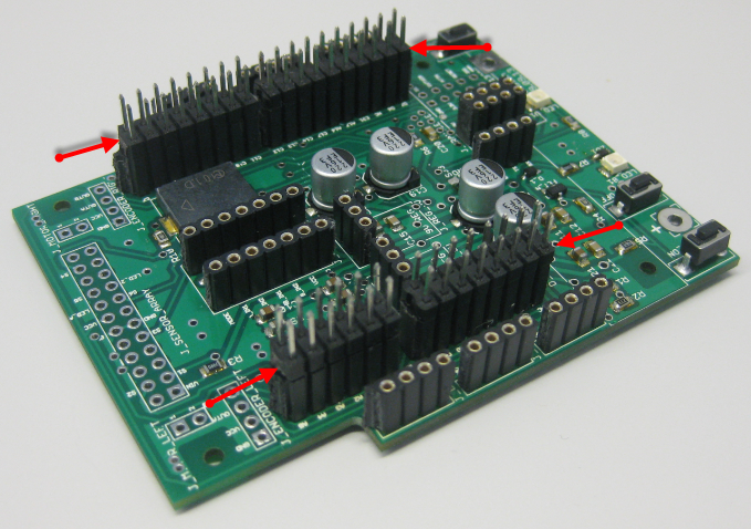
Distance Headers Mounted on Base Board
Then, the FRDM-KL25Z (or any other FRDM board) is placed/connected on top of it:

FRDM-KL25Z on top of the Robo Base Board
The result will look similar to this (picture below shows the prototype base board):

Example Intro_Zumo_Robot
In above picture, the green Freescale IEEE802.15.4 transceiver card is not connected yet, as it needs a small adapter PCB.
Next Steps
Next week all the other components get populated, assembled and tested. Already identified a small problem with the connection to the IEEE802.15.4 transceiver connection: the connector for it is too close to the connector for the FRDM board. But this problem can be easily (mechanically) solved. Additionally, the FRDM board cannot be easily removed due the friction of the dual header rows (still thinking about a better solution).
Kickstarter?
I have received several questions/requests if they could get a board/robot. Simple answer: yes, if you register for my class :mrgreen:.
But this triggeredd some thinking about the next iteration. With the current batch of 40 robots/PCB’s, the budgetary costs for a single robot are:
- US$ 20: Base PCB (dual layer, silk screen, including initial setup costs)
- US$ 20: Components (headers, resistors, buttons, LED’s, …)
- US$ 110: Pololu components (Zumo chassis, two DC motors, motor driver, two DC/DC converters, two quadrature encoders, line sensor, Zumo blade)
- US$15: FRDM-KL25Z Board
- nRF24L01 transceiver (US$2.75) and/or Bluetooth module (around US$6), ultrasonic module (around US$3.00) and added digital or I2C sensors.
So makes around US$150 without the FRDM Board/transceivers/extra sensors. The board features connectors for a serial-to-USB Bluetooth module and the nRF24L01+. The most expensive parts are the motors and the quadrature encoders. The DC/DC converters, motor driver and quadrature encoders could be integrated on the PCB to reduce costs. Additionally, we are looking into having the boards produced with all the SMD components already populated. That would it make it really easy to build your own robot.
Of course everything is about quantities. If there would be enough demand, I think a robot could be possible for US$100? But would there be enough demand for such a robot? I you want to have a closer look: On GitHub I have published the Eagle files, schematics and an initial version of the assembly guide.
Let me know what you think and post a comment to let me know if you are interested ![]() in participating. Then this could lead to a KickStarter or similar project :-)?
in participating. Then this could lead to a KickStarter or similar project :-)?
Happy Zumoing 🙂

Pingback: Overview of ARM Microcontrollers and Tools | MCU on Eclipse
Pingback: Zumo Robot assembled | MCU on Eclipse
How do you register for class?
LikeLike
Unfortunately this is not an online class/course, so you would have to register as a student at the university of Lucerne.
LikeLike
I didn’t realize you had designed and built your own chassis PCB. So cool!
So if you do a second revision of the board are you going to support the optical encoders? Is that what you meant when you were saying you were designing the post-processing circuit?
LikeLike
Due lack of time, the next semester we will use the same chassis PCB we designed (we still have a few boards, hopefully enough). But we will use an extra small PCB with an Op-Amp and a DA-Converter over I2C which does the signal processing. Then the next revision of the board will have that included, plus some other gadgets.
LikeLike
I want to move to Lucerne and sign-up.
LikeLike
Pingback: Mini-Sumo Robot Competition May 2014 in Horw | MCU on Eclipse
The Zumo Robot project is a very interesting project to try to follow. It could be easier to follow if a kit were avaliable. I got the Zumo Robot, the quadrature encoders and the FRDM board. I hope I can get it working soon. Thanks for posting all that great information.
LikeLike
Hi Jorge,
yes, I love that Zumo chassis and robot too. Yes, there is a kit available (from Pololu), but using the normal chassis and shield. The easiest way is to use that kit (I wrote about it in https://mcuoneclipse.com/2013/01/31/the-freedom-zumo-robot/). But this does not support quadrature encoders. Which encoders are you using? The ‘wheel’ ones (https://mcuoneclipse.com/2013/06/15/adding-quadrature-encoder-to-the-zumo-chassis/) or the motor shaft ones (https://mcuoneclipse.com/2014/03/08/processing-the-pololu-motor-shaft-encoders/)?
See as well for all related robotics articles in https://mcuoneclipse.com/compendium/#Robotics
LikeLike