After my first post using a Bluetooth module, things have evolved a bit. The challenge with these Bluetooth modules is: they look the same, but having different firmware. I did not fully realize that until I have ordered another bluetooth module from dx.com:
DX.com Bluetooth Module (HC-06)
That module comes already on a carrier, so I assumed I can use the same driver as for my other module. I was wrong :-(.
HC-05 or HC-06
My earlier module which I received from another source (without an adapter, see this post) has a different firmware on it, known as HC-05, while my DX.com module has a HC-06 firmware. To be clear: the modules are the same, but the software/firmware on it is different, and the firmware uses the pins differently too 😦

HC-06 and HC-05 (Source Wavesen Data Sheet)
💡 Check out this post which explains how to re-program the firmware of the device with firmware programming adapter: http://byron76.blogspot.ch/2011/09/hc05-firmware.html
The HC-05 has the ‘full’ firmware on it: many AT commands, and can be both master and slave module. The HC-06 firmware on the other hand only can be a slave device, with very limited AT commands.
Or in other words:
- The HC-05 module can build a connection to other modules. E.g. a Robot being a master and connecting to slave bluetooth module. Or in slave mode to make a wireless bridge to a notebook.
- The HC-06 module only can be a slave. This makes it only useful for say connecting a notebook as a master to a robot with a slave module e.g. for a wireless serial bridge.
For most use cases the HC-06 is enough, as typically I want to have a wireless UART connection to my devices from my notebook.
JY-MCU V1.5 Module
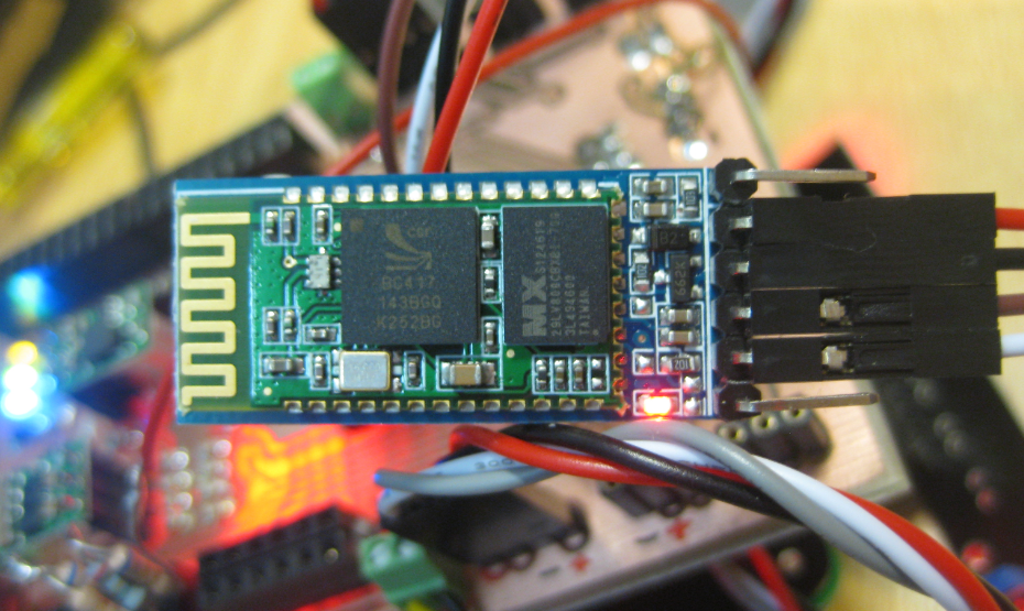
Below is an image of the JY-MCU HC-06 (JY-MCU V1.5) module. The module came with a 4-pin header, and I have added the pins for STATE and KEY, and removed the plastic around the module to get access to the pins:
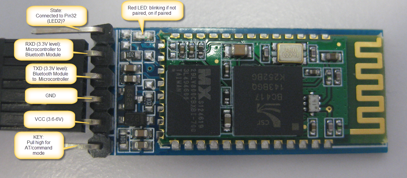
HC-06 Top Side
Pins
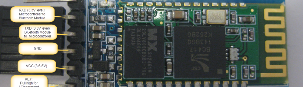
On the bottom side there are labels for the signal direction and voltage levels:

JY-MCU BT_BOARD V1.05 Bottom Side
- KEY: according to the data sheet, I need to pull-up this pin while power-on-reset of the module to enforce AT mode. I have not been able to verify this yet. I have been told that some modules have this pin not connected at all?
- VCC is indicated in the range of 3.6V-6V. The module worked for me both with 3.3V and 5V.
- GND: Ground
- TXD: serial output of the module, to be connected to RX of the microcontroller. Note that this signal is using 3.3V logic level
- RXD: serial input of the module, to be connected to the TX of the microcontroller. Note that this signal is using 3.3V logic levels.
- STATE: connected to LED2 (Pin32) of the module, but no meaning? At least on my module the pin was always low, regardless if paired or not.
Different AT commands
On the HC-05 module, I send “AT\r\n” to the device, and then it responds with “OK\r\n”.
But on the HC-06, the protocol is different 😦 I need to send “AT” (without the new-line characters), and I receive “OK” (without the new-line characters).
The logic analyzer shows this behavior too: AT command sent to the device:

AT Command sent to Device
OK response from the device with no “\r\n” at the end:

OK Response from the Device
The missing “\r\n” is present for all commands of the HC-06 firmware. As as this is not enough, there are very few command possible. The table below shows all the HC-06 firmware commands with the response:
| Command | Response | Comment |
|---|---|---|
| AT | OK | Used to verify communication |
| AT+VERSION | OKlinvorV1.8 | The firmware version (version might depend on firmware) |
| AT+NAMExyz | OKsetname | Sets the module name to “xyz” |
| AT+PIN1234 | OKsetPIN | Sets the module PIN to 1234 |
| AT+BAUD1 | OK1200 | Sets the baud rate to 1200 |
| AT+BAUD2 | OK2400 | Sets the baud rate to 2400 |
| AT+BAUD3 | OK4800 | Sets the baud rate to 4800 |
| AT+BAUD4 | OK9600 | Sets the baud rate to 9600 |
| AT+BAUD5 | OK19200 | Sets the baud rate to 19200 |
| AT+BAUD6 | OK38400 | Sets the baud rate to 38400 |
| AT+BAUD7 | OK57600 | Sets the baud rate to 57600 |
| AT+BAUD8 | OK115200 | Sets the baud rate to 115200 |
| AT+BAUD9 | OK230400 | Sets the baud rate to 230400 |
| AT+BAUDA | OK460800 | Sets the baud rate to 460800 |
| AT+BAUDB | OK921600 | Sets the baud rate to 921600 |
| AT+BAUDC | OK1382400 | Sets the baud rate to 1382400 |
That’s it.
Firmware Timing
As this is not enough, my driver did not work even with the new commands implemented. The HC-05 firmware as sending a response back in less than 300 ms, while the HC-06 firmware needs more than 500 ms until there is a response:

Delay between Command and Response
So for this I had to introduce a user configurable delay in the component.
Processor Expert Component
With this knowledge, the Processor Expert Bluetooth component has been updated to support both the HC-05 and HC-06 firmware:

Bluetooth Component Supporting HC-05 and HC-06
- Firmware to select between HC-05 and HC-06
- Configurable Response Time if the module needs longer for commands
- Optional State and CMD pins
If the HC-05 firmware is selected, then the component automatically disables the functionality methods not present/supported in the firmware (grayed out methods):

Bluetooth Module Methods
Command Line Interface
The Processor Expert component features an optional command line interface:
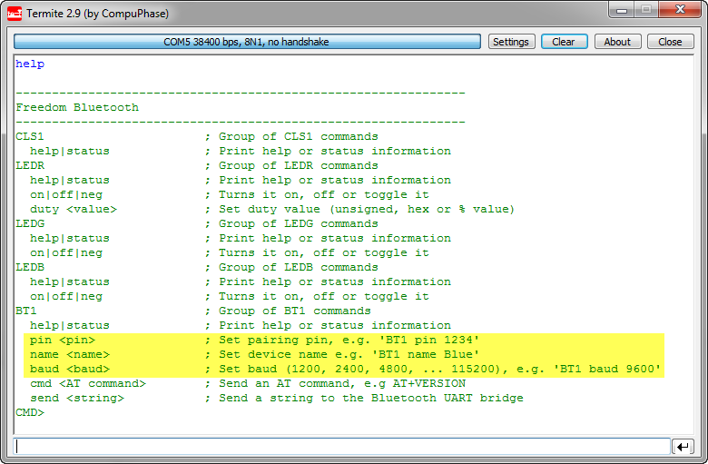
HC-06 Shell Commands
With this, I can change the pairing pin, device name or baud, beside of sending AT commands or sending a string over the wireless bridge.
💡 Changing the pairing/name/baud will be effective after resetting the device. Keep in mind if you change the baud, this will change the baud as well between the module and the microcontroller.
The ‘status’ command issues an AT command to the device to see if it responds, plus shows the firmware version:

BT1 Status with Module Firmware
❗ Status and AT commands can only be used if the device is not paired yet (means: while the red LED is blinking).
Connecting to the Bluetooth Module
The Bluetooth module runs the SPP (Serial Protocol over Bluetooth) protocol. So any device supporting SPP can connect to it. On a PC this looks like a virtual COM port. I show here the steps for Windows (running Windows 7).
❗ It seems that Apple (iPhone, iPAD, etc) does *not* support SPP, so connecting with an iPhone is not possible. Android (which I did not try) should work, or any PC machine with Bluetooth.
Before connecting, make sure the module is powered and ready to pair. The red LED on the module indicates the status:
- blinking: ready to pair
- steady on: paired
From the Device Manager, select ‘Add a Device’:

Device Manager with Add a Device
Then the new device should show up:
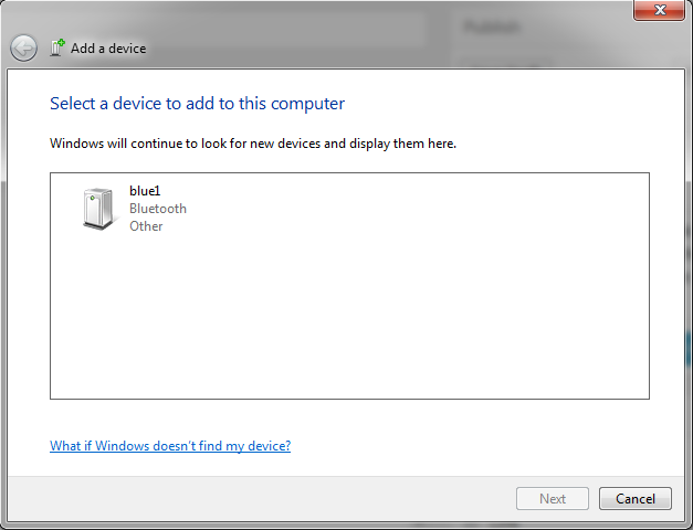
Add a device Dialog
💡 the name of the device shows here for me ‘blue1’, as I have named it as such. But it might show up for you as ‘linvor’ (default) or ‘other’.
Select the device and press ‘Next’. In the next dialog select ‘Enter the device’s pairing code’:

Enter the device’s paring code
The default pairing code is 1234:

Enter the pairing code for the device
Pressing next, and device drivers will be installed:

Installing device drivers
Then the device is ready to use:

Your Device is ready to use
And the confirmation dialog shows up:
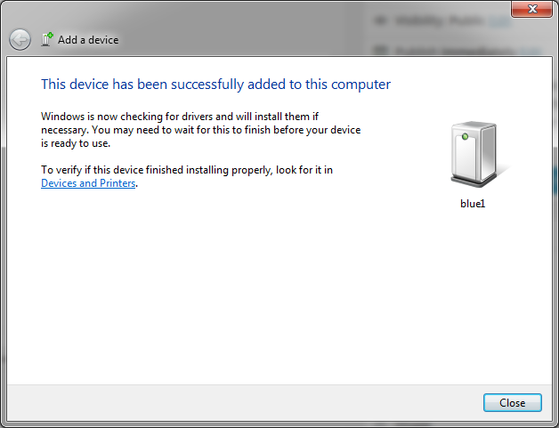
This device has been successfully added to this computer
COM Port used by Device
Checking the properties on the newly added device shows that it supports SPP. And it shows the virtual COM port used:

Device Services
❗ Note that if I check the COM ports in the device manager, then I see that actually two COM ports have been added. Only the one shown above with the SPP protocol will work. It is unclear to me why there is a second port?
Connecting to the Wireless Bluetooth Bridge
Using that COM port shown for the SPP service, I can connect with a terminal program on the host PC to my board. Basically this gives me a wireless bridge over Bluetooth to my board. So from my PC I can open a terminal window and type in some commands, which are parsed by the Shell on the FRDM board, and it responds back to the terminal on the PC:

Wireless Bluetooth Bridge Connection
❗ Make sure you use the COM port used for the SPP service, and that it matches the baud settings of the communication between the microcontroller and the Bluetooth module. I’m using above the default of 9600 baud. It is possible to change/increase the baud as explained above, as 9600 is not very fast. Only be sure that you not exceed the baud to a value which cannot be handled by your PC. It should work ok up to a baud of 115200.
Once connected, the red LED on the Bluetooth module is always on.

Pairing LED
While connected, the module is in ‘transparent’ mode, and does not accept AT commands. Below is an example where I try to send an AT command from the microcontroller while the Bluetooth module is connected to the host PC:
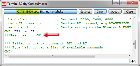
Trying to send AT commands from the microcontroller while connected to PC
Instead, what I send to the UART ends up transparently on the host PC:

Bluetooth Module in Transparent Mode
Wireless Bridge
Everything I send to the virtual COM port ends up on the Bluetooth module, which then sends the commands to the microcontroller using the RX and TX connection between the microcontroller and the module. With this, it is very easy to send/receive commands using the Processor Expert Shell component, and the implementation are just a few lines:
/** * \file * \brief This is the implementation module for the shell * \author Erich Styger * * This interface file is used for a console and terminal. * That way we can interact with the target and change settings using a shell implementation. */ #include "Shell.h" #include "CLS1.h" #include "LEDR.h" #include "LEDG.h" #include "LEDB.h" #include "BT1.h" static const CLS1_ParseCommandCallback CmdParserTable[] = { CLS1_ParseCommand, #if LEDR_PARSE_COMMAND_ENABLED LEDR_ParseCommand, #endif #if LEDG_PARSE_COMMAND_ENABLED LEDG_ParseCommand, #endif #if LEDB_PARSE_COMMAND_ENABLED LEDB_ParseCommand, #endif #if BT1_PARSE_COMMAND_ENABLED BT1_ParseCommand, #endif NULL /* sentinel */ }; /* Bluetooth stdio */ static CLS1_ConstStdIOType BT_stdio = { (CLS1_StdIO_In_FctType)BT1_StdIOReadChar, /* stdin */ (CLS1_StdIO_OutErr_FctType)BT1_StdIOSendChar, /* stdout */ (CLS1_StdIO_OutErr_FctType)BT1_StdIOSendChar, /* stderr */ BT1_StdIOKeyPressed /* if input is not empty */ }; void SHELL_Run(void) { unsigned char buf[32]; unsigned char bTbuf[32]; buf[0]='\0'; bTbuf[0]='\0'; CLS1_ParseWithCommandTable((unsigned char*)CLS1_CMD_HELP, CLS1_GetStdio(), CmdParserTable); for(;;) { (void)CLS1_ReadAndParseWithCommandTable(buf, sizeof(buf), CLS1_GetStdio(), CmdParserTable); (void)CLS1_ReadAndParseWithCommandTable(bTbuf, sizeof(bTbuf), &BT_stdio, CmdParserTable); } }Unbinding and Trouble Shooting
In case there are issues with connecting to the module, it is necessary to unbind and re-bind (connect) to the module. It happened to me sometimes I’m able to connect once, but then not any more. In that case the following steps help:
- Close any terminal program potentially connected to the Bluetooth virtual COM port.
- Unpower the Bluetooth module so it is not visible any more to the PC.
- Right click on the device in the Windows Device manager (or Devices and Printer group) and select ‘Remove Device’:
Unbinding Bluetooth Device
- Re-power the module: the red LED shall be blinking as not connected.
- Search for the device in the device manager (as above), and connect again to the device with a pairing pin.
- Connect to the module using the COM port specified for the SPP service.
That way I was always able to recover connection to my module. See as well this post which helped me to solve my problem.
Sources
All the component sources discussed are available on GitHub. Additionally, the FRDM-KL25Z Bluetooth example project has been updated to support both the HC-05 and HC-06 modules.
Happy Bluetoothing 🙂


Hi Erich,
Maybe you can talk about 24L01+ and Ethernet communications? Do you have this Beans?
Thanks,
Alex Vecchio
Brasil
LikeLike
Hi Alex,
do you mean the 24L01 from Nordic Semiconductor? No, I do not have beans for this one. I do have an Ethernet Shield, but had not much time to work on it. It will be one of the next things for sure.
LikeLike
Ouch… Fastest answer i`ve ever seen!
Yes. I am talking about the Nordic Semiconductor 24L01. Maybe this can be a really cheap solution to control a freedom board from another freedom board wirelessly.
Other thing is to control a freedom board through the intranet.
I am waiting for your new posts. Thanks for this excellent job you are doing.
LikeLike
Sometimes I never sleep 🙂
yes, that Nordic module is really interesting, altough I do not have one (yet). The HC-06 Bluetooth one (or the HC05) are really cheap: less then $10, and at least the HC-05 one can be used to control another FRDM board.
LikeLike
Hi Erich,
I think we can control a lot of Freedom boards simultaneously with the 24L01+ but we cannot do this with bluetooth devices. Right?
LikeLike
Yes, doing this with the HC-05 probably is not easily possible. For the use case you describe I’m using an IEEE802.15.4 module which can build up star or mesh networks.
LikeLike
Hi Erich,
These modules are really cheap at (http://yourduino.com/sunshop2/index.php?l=product_detail&p=188).
I have bought from them and the parts were very reasonable and shipping was good too!
Cheers,
Tom
LikeLike
Hi Tom,
they are *increcibly* cheap, thanks for the link. I guess will order a few to try it out. Once concern I have: the derivers I have seen are all GPL2 which is a concern. Have you seen (or using) LGPL or BSD style drivers or stacks? Otherwise it looks I need to develop everything from ground up which is not ideal.
LikeLike
Erich,
Erich,
No I haven’t seen LGPL or BSD stacks but I haven’t been looking that hard. There is a library at (arduino-info.wikispaces.com/nRF24L01-RF24-Examples) which may be something you can leverage.
LikeLike
Hi Tom,
yes, I already found that library, but it is GPL2 as well, so not very usable for anything than true hobby projects.
Anyway, I have ordered a handful of modules, and whenever I find time, I’ll start writing a BSD style driver. Contributions are always welcome 🙂
Erich
LikeLike
Maybe you can use this for anything.
https://code.google.com/p/nrf24l01/
I start to dig any reference for 24L01 and BSD.
LikeLike
Hi Alex,
thanks for the link. Good information.
LikeLike
I think this can be useful too.
LikeLike
Hi Alex,
yes, this one is about what I was looking for, thanks!
LikeLike
Hi Erich
I got some experience with one of these modules on a project. I think they are all more or less the same, but for the firmware (as you point out). The circuit is a CSR reference design. The CSR chip is based around a core architecture developed at Cambridge university. You can get the development tools from their web site (easy to find), and develop your own firmware for the module. I never got so far as to download all that, not sure about what the cost is etc. I would guess there is a reference design for the firmware as well, which is what all of these different firmware versions would be based upon.
LikeLike
Hi Dusty,
yes, I have found the article from Byron (http://byron76.blogspot.ch/2011/09/hc05-firmware.html) which points to the CSR site. I have registered and downloaded the tools, but not done much with it. I did not know that this has been developed at Cambridge, which is interesting.
LikeLike
Hi, Erich!
You have done a very good job by creating a component like this.
Two weeks ago, I have bought a BC04 bluetooth module from ElectroDragon (which is a little bit different from HC05 or HC06 as firmware) and this thing involved, for me, some changes into your component source code.
After implementing all changes, I would like to add a new BC04 firmware to
“Bluetooth_EBGT” component project. The problem with that is caused by the fact that I cannot import very well your project, because when I try to edit the source code of a method I get the following error : “Source Code missing in default driver. It could be present in a prg.”.
Any help would be greatly appreciated.
Thank you.
LikeLike
Hi Surdeanu,
I don’t think I have seen that error myself, so not sure what is causing this? Maybe you could email me your changes/source code and I’m happy to have it incorporated into the Processor Expert component. Send it to the email I have listed at the end of the ‘About’ page of this blog.
Thanks for contributing to that project!
LikeLike
Ok. Then, I think that I will send it tomorrow, because today I want to do some other tests.
Have a nice day.
LikeLike
Pingback: Yet another Bluetooth Firmware: BC04 | MCU on Eclipse
Pingback: Tutorial: Ultra Low Cost 2.4 GHz Wireless Transceiver with the FRDM Board | MCU on Eclipse
Pingback: Mini Sumo Robot Competition running with FRDM-KL25Z | MCU on Eclipse
hi can u please give me a help on a Eclipse code to control Bluetooth module
LikeLike
have a look at the example here:
https://github.com/ErichStyger/mcuoneclipse/tree/master/Examples/CodeWarrior/FRDM-KL25Z/Freedom_Blue
LikeLike
Pingback: Zumo Robot Chassis PCB arrived! | MCU on Eclipse
Hi Erich,
thx a lot for showing the differences between HC-05 and HC-06 module !
I happened to get my HC-06 work with a Trust USB-BT dongle and WinXP32.
Just shortcut the Tx/Rx on the module and used Comport Toolkit as a terminal to see the looped back chars.
If longer blocks of data are sent the delay decreases to somewhat 90msecs. But that’s all for the good news.
The HC-06 does not establish working mode (steady LED) when I use my lenovo T500 with win7-64. I can connect the device, send pairing pin and two successive COMxy ports are shown in device manager. But the first where the SPP is assigned to can not be accessed by my terminal programs and the LED on the HC-06 keeps flashing indicating AT mode :(.
Same situation with my Galaxy-S2 GT-i9100, it finds it, pairing pin input but HC-06 stays in AT mode.
Has anyone an idea or solution about that ???
All the best, Tom.
LikeLike
Hi Tom,
I had some problems with another notebook, where I was not able to establish connection: here it helped to re-install the drivers on the notebook as explained in the article.
On another notebook I used a cheap bluetooth dongle (under Windows7 64bit). I never got it working to connect to the bluetooth module, while it worked on another machine with XP.
So I just make the guess that there might be a similar problem in your case, but with the internal bluetooth module? It might be worthwile to try an external bluetooth module?
LikeLike
Hi Erich,
Thanks for your comments.
With Android I’ve got it work. After inputting the pairing sequence on the phone the HC06 stays in AT mode but if my app runs it connects and switches to SPP mode :).
I’ll try to reinstall the win7 BT drivers and see what will happen…
Good luck, Tom.
LikeLike
Hmm, yes, this is true on Windows too: only if I connect to the COM port with my terminal, it changes from AT to transparent mode. I thought I had mentioned this, but probably not bold enough…..
So here again: the connection only happens if actually connected on the host to the virtual COM Port 🙂
LikeLike
yepp,
But with my win7-64 I see both virtual COM ports created by the BT in the device manager but can not access the lower numbered one with any terminal program…
This works with XP-32.
LikeLike
Yes, I have the same: one of the ports is ‘dead’, not sure why. But works on the other one.
LikeLike
Pingback: Zumo Robot assembled | MCU on Eclipse
hey can you tell me can we pair 2 hc-06 module at the same time .???…
LikeLike
you mean to have a connection from the host PC to two modules the same time? yes.
To pair two HC-06 modules to each other: no.
LikeLike
I have a problem when I compile the file bth1.h gives me an error on line 331: byte BT1_ParseCommand (const unsigned char * cmd, bool * handled, CLS1_StdIOType const * io);
LikeLike
Hi Diego,
what kind of error message do you get? I tried again my example on GitHub and it works fine for me. Have you loaded the latest Processor Expert components from GitHub too? It looks like it is an issue with the shell, and maybe you are using an older version of the code/components?
Erich
LikeLike
fix the error, I wanted to ask you for help with the command line interface, as you do to get the settings? because it recognizes the port but when writing AT commands nothing happens. If you could help me or pass me your mail. Thanks in advance.
LikeLike
If nothing happens if you write AT commands, this typically means that the Bluetooth module already has been connected to the PC host. If the module is connected, then the LED is on (compared to be in blinking mode if not paired, where it accepts AT commands). Another reason for the AT commands not working is a wrong UART baud configuration. By default the modules operate with 9600 baud. Please verify with a logic analyzer if that baud is used. I hope this helps?
LikeLike
HI
i am presently working on a project that requires microcontroller to microcontroller wireless communication. i was wondering if we could do this using 2 BLUETOOTH hc06 or hc05, by simply interfacing 1 of the modules with the transmitting microcontroller and interfacing the second with the receiving microcontroller.
i have been able to pair my HC06 module with laptop and mobile. when i use a laptop on 1 end i simply have an option to enter the pairing code into my laptop but while working with 2 bluetooth modules the problem i am facing is how do i enter the pairing code.
LikeLike
Hi,
the HC-06 only can be slave, so you cannot connect two HC-06 with each other. It should be possible to connect a HC-06 with a HC-05 in master mode, but I have not tried this yet.
LikeLike
Hello,
I have HC-06, and I need to change data bits 8 to 7 (required for my application). I cant find any info about setting data bits. Maybe you know something about that.. is it possible?
LikeLike
Yes, some microcontrollers can configure the UART to different than 8bits (e.g. to 7 bits).
To my knowledge this is not possible with Kinetis. But I have not checked deeply on this.
LikeLike
hello, hey when I run the program the terminal gives me this
————————————————– ————
My Project Name
————————————————– ————
CLS1; Group of CLS1 commands
help | status; Print status information or help
CMD>
AT write the codes and nothing happens
LikeLike
Hi Diego,
are you using my example from GitHub? From the shell output it looks like you have not added the command line interface to the Bluetooth module, as it does not show up with help. Be aware that if the HC-06 LED is not blinking, the module already connected to a host, and it does not accept any AT commands (the AT commands are sent to the host).
LikeLike
Hi,
That was great, but I have a question, Can my PC connect to more than one module.
I want to create an app in the PC that monitor many bluetooth modules at the same time.
Is that possible?
Thanks
LikeLike
Hi,
yes, you can connect to many modules with your PC. They will show up with different COM ports.
LikeLike
I’ll immediately snatch your rss feed as I can not to find your e-mail
subscription hyperlink or e-newsletter service. Do you’ve
any? Kindly let me recognize in order that I could subscribe.
Thanks.
LikeLike
It is the ‘Follow’ button below the RSS feed link on the right side of the page.
LikeLike
Hi Erich,
Thanks for sharing the result with such great detail.
I’m planning to use this bluetooth module with Arduino Pro Mini 3.3V model – in this case, the logic level would be needless, right?
Best reagards,
Jami
LikeLike
Hi Jami,
yes, the module operates with 3.3V logic levels. You just need to be careful about the supply voltage. My modules say 3.6V-6V, but I was able to use them with 3.3V without problems. That might depend on the module.
Erich
LikeLike
Hi Erich,
Thanks for the reply.
I still haven’t got HC-06 but quickly tested an HC-05 (also marked with 3.6V-6V) with the Arduino. They both are well integrated.
Jami
LikeLike
Excellent site, thanks, lots of good info,
I wonder if you can assist with my little challenge?
My project is to provide a wireless connection between a racing yacht’s Nav computer (a B&G Hercules Performance Unit) and my Android phone using my HT-06 (Ver 1.06).
To build up some expertise, I’m practicing at home by trying to get the connection going by connecting the HT-06 to my Garmin GPS72 handheld GPS receiver. I’m bluetoothing to the HT-06 with my laptop and a cheap USB dongle using a good terminal emulator (Reflection).
When connecting the GPS72 to the laptop with a cable, it comes in on USB at COM04 and my terminal emulator happily talks to it at 4800 8/None.
However, when trying to get the laptop to talk to the GPS72 with the HT-05, I get the connectionup and running (solid led) and I’m receiving data from the GPS72, but on the terminal see the pulses of data, but instead of getting interpretable data, there are strings of, like “~f~~”
I know it’s because I have an incompatibility in comms protocols and have tweaked the terminal through speeds and parity with no joy.
I suspect I have to configure the HT-06 to use 4800 8/N, but not having the connectors to connect the laptop to the HT-05 I’m not able to tweak the coms speeds from the laptop, so I’m wondering if it is at all possible to send AT commands from the laptop to the HT-06 over BT?
LikeLike
Hi Alan,
thanks for your kind words :-).
As for your question: you cannot send AT commands over the air to the Bluetooth module: if it is connected, it is in transparent mode and will send the incoming data to the other side (so you cannot reach the Bluetooth controller with AT commands).
As for the protocol errors: can you hook up a logic analyzer on the serial signals to see what is going on? That would give a clue if the baud is somewhat wrong or outside the spec, if parity/etc is used.
LikeLike
And thanks for your prompt reply. It’s as I feared. Odd, eh, that they design a slave module – presumably to connect to a dumb device, that can’t be configured by the master.
One more question, if I may. When I do get to set the comms protocol with an AT command, say AT+BAUD3, does that setting persist over a power reset? i.e. can I set it in the lab, and then rely on it in the field?
LikeLike
Yes, the settings persist in the device.
LikeLike
Hi Erich,
Back again, sorry.
I suspect I have a faulty device (HC-06 Ver 1.06), and being a software guy, a class world-renowned for unfairly blaming the hardware, I have tried to be thorough in my testing.
The final clincher for me is that when I send AT commands over the serial port I get no response at all.
I have a breakout board on the serial line and can see the RX line flash its led.
The HC-06 is flashing.
I am using 232Analyzer to send data 9600 8 N 1 and am sending AT.
I have read the HC Serial Bluetooth Products User Instructional Manual, http://www.exp-tech.de/service/datasheet/HC-Serial-Bluetooth-Products.pdf which seems quite straightforward if a little confusing.
And I’m still receiving corrupt data over the bluetooth connection when sending ASCII at 9600 8 N 1.
Before I send off for a replacement, is there anything else that you know that I can try to talk to my baby?
Cheers, and thanks for your patience.
LikeLike
If the HC06 is flashing, then it is not connected to the PC. You really would need a logic analyzer like the Salae one so you can inspect the bits and bytes on the line. Maybe something is wrongly configured on your side (baud?), and only with flashing LEDs you will not see it. I’m a software guy too, but developing software for hardware means a scope and a logic analyzer is key. Without it, it is like programming without a PC monitor :-(.
LikeLike
I’m a novice with these boards as well but it appears that you’re trying to send AT commands and the chip is not in that mode. My board had a pin labeled “KEY”.Tie that pin to the VCC source, Now disrupt and re-establish the power to the HC-06 leaving the “Key” tied to power. The unit will reboot in AT mode. To reset to Normal mode remove KEY from Vcc and disrupt and re-establish power. I was also able to easily pair with this device using “1234” as the code. Once that was done I opened up TeraTerm Pro and selected the comm port configured for my BT. I was talking to a Mini Pro quite quickly…Hope this helps…
LikeLike
Hello Erich,
I am using an HC-05 board (found on eBay http://www.ebay.com/itm/150843209961?ssPageName=STRK:MEWNX:IT&_trksid=p3984.m1497.l2649).
I am trying to configure it using the AT commands. This can only be done using the physical serial connection to the PC, is that correct? I believe I managed to get the board into configuration mode using the KEY pin, since the LED now blinks differently. However, when I use Termite to send AT commands (simply with AT\r\n), the board responses with things such as: x, then xÅr\n, then Ap\ûpÿ, etc every time I resend the AT command. I guess it could be some problem with the coding of the commands such as wrong font… But still I don’t understand why it responds differently to a unique command.
Can you help? Thank you in advance!
Remi
LikeLike
Hi Remi,
this does not sound like a font problem. Can you hook up a logic analyzer to see what the module really responds? It very well could be that this module is not a HC-05 one, but a different one with different firmware?
Erich
LikeLike
I have concluded that the HC-06 device does not conform to RS232 standards.
I have spent 6 weeks messing with it ( well, 2 separately purchased boards) connected to my PC (XP and W7) using some pretty clever terminal emulators (realTerm, Commfront 232Analyser, Reflection ) and I have concluded that it doesn’t generate the 10 bit per character (start, 8 bit data, stop) syntax defined by RS232.
I was unable to get it to respond to an AT command, nor could I get it to transmit text at its default speed of 9600, N 8,1 or any other combination.
All the folks successfully using it are using Arduino. I haven’t found anyone using it successfully in conventional RS232 PC mode.
I have thrown them away and spent $125 on an older but functional RS232 to Bluetoth adapter. It’s pretty clunky, requiring a PC Utility to configure it, but it works!
LikeLike
Hi Erich,
Thanks for the reply. I don’t have a logic analyzer. I have tested somewhat further and I have noticed that using Termite, when I change the baud rate to a lower value, I get a response identical to what I send to the device. If I put a higher baud rate, I start getting all this nonsense… Also, I should mention that I don’t have a serial connection on my computer, so I make use of a RS232 to USB converter from Logilink. So the baud rate which I change is probably the baud between the PC and the converter.
LikeLike
Hi Remi,
yes, the baud is only applied to the physical serial line, not for the USB communication. for a USB-CDC connection the baud is pretty much useless.
LikeLike
Just read Allan and Tom’s comments. If I understand it, I should have a RS232 to TTL converter between my USB to RS232 converter and the HC-05 module because the HC-05 “talks” in TTL and not RS232?
LikeLike
Hi Remi,
The HC-05 module does not use TTL (0-5V) levels, but 0-3.3V. RS-232 uses completely different voltage levels (3 to 15V and -3 to -15V, see http://en.wikipedia.org/wiki/RS-232), so they are not compatible. Your PC or RS-232-USB converter expects that different voltage, so if you want to connect the bluetooth module to your PC, then you need to use a level shifter like a Maxim 3232 or similar. The logic levels of 0-3.3V of the module are only to be used with something which has the same voltage levels, e.g. a microcontroller.
LikeLike
Hi Erich, thanks for the answers. The daughter board which I bought with the HC-05 module mounted on it has such a MAX3232 level shifter (see ebay link above).
I know that I was able to switch the board into AT mode, at least from the different blinking of the LED. I tried using different baud rates for the serial communication to the bluetooth module, no success. I made sure the TX and RX are correct, used different voltage levels (5.0 and 3.3 volts) for both the Vcc and the Key. I tried to reset the device using AT+RESET in case the transmission to the device was functioning correctly but not the reception from it. I have bought 3 of these devices and tested all, they give the same results.
I am running out of ideas…
Btw, what is the tiny push button on the daughter boards for?
LikeLike
I have not used these modules. But it sounds you have nothing than the modules? No user manual, schematics or something you absolutely need to understand this module. I checked that ebay page, but there was no more information than the pictures. You even cannot be sure what kind of firmware is on the module without this information. And without the right tools (aka logic analyzer) it is like fishing in the dark 😦
LikeLike
Oh, I see, there *is* indeed a data sheet :-). What the ‘Key’ does depends on the firmware on the module. Many firmware are using it to get back into the ‘command’ mode. But not clear to me which firmware really is on this module.
LikeLike
And I have found in the description what ‘key’ is supposed to do. Key connects 3.3.V to PIO11:
3. PIO11, control the module working mode, High=AT commands receiving mode(Commands response mode), Low
or NC= Bluetooth module normally working.
LikeLike
Hi Remi,
I can confirm that a Maxim 3232 works like a charm with the HC-06 to provide an interface between a PC serial COM port and the HC-06, notwithstanding the discrepancy between the TTL and MCU voltages, as it handles the voltage range of 3.3 to 5V.
I have just taken delivery of my Maxim board and am happily bluetoothing between my PC and my Android phone.
I have also connected my Garmin GPS72, configured to report using NMEA at 4800 to my Android phone with this configuration.
You don’t need a logic analyser.
You do have to cross the TXD and RXD lines between the HC-06 and the Maxim.
It’s taken me almost eight weeks to work this out, but success comes to the diligent!
LikeLike
Alan,
Sorry, but you are missing basic electrical skills and you did not rtfm.
The HC-05/6 as well as all the other BT-modules from other suppliers provide a 3,3V digital logic interface. The guys using an arduino wire the 3,3V TxD/RxD signals of the arduino UART to the corresponding pins on the HC-05 module, the arduino provides a virtual COMport via USB to the connected PC/Laptop so there is no RS232 within that signal way to be used.
Your PC (COM1:) has a standard RS232 interface what is electrically on a total different planet (use wikipedia and READ please) as the 3,3V or 5V digital logic interface. Or you use an USB->RS232 converter cable but that’s the same…
That’s why you could not make a working connection… It is an electrical problem !
http://www.ebay.de/itm/RS232-Serial-Port-to-TTL-Digital-Converter-Module-SP3232EEN-5V-3-3V-Jump-Kables-/400676853830?pt=Wissenschaftliche_Ger%C3%A4te&hash=item5d4a339846
Use something like that and everything should be fine ;o).
Good luck, tom.
LikeLike
AHA!, at last some light in the wilderness.
Silly me…When I did R TFM (extensively), the doco consistently (if slightly incoherently) referred to the HC-05 as a serial BT adapter, and from my software background, serial MEANS RS232!
Nowhere did they say that the headers on the card talk TTL not RS232. I have discusses my problem extensively on forums and emails, I knew I was making a simple mistake, but no-one was smart enough to spot my confusion.
The traps for young players trying to reach across technologies! Thanks Tom, so much for your clarification.
LikeLike
hi..my project is to send the data using bluetooth module.is that possible if i want to connect hc-05 from PIC1 as a transmitter and hc-06 as a receiver at PIC2 ?
LikeLike
The HC-06 Bluetooth module only can be a slave, but the HC-05 is able to be a master too. So with the HC-05 as master, you should be able to connect from teh HC-06 module. What microcontroller (PIC, TI, Freescale, STM) does not matter 🙂
LikeLike
Hi erich
I have a module (DAQ Module) to get data from strain gage in rotating sensor. The module use USB cable communication to my computer (It has Ft232 serial to Usb IC in its daughterboard).
Now, I want to get the data via Bluetooth, and I already bought HC 05. Unfortunately, Because of the module architecture, I can’t get its rx tx to my HC 05.
In the HC 05 datasheet, I see the USB Dp and Dm port, and they said it can transfer data via usb protocol (v 1.1). After that, I connect my module’s USB port (USB type B) to the Dp and the Dm port, and I connect the Vcc and Gnd to my power bank. The HC 05 is connected to my comp, but it is connected to my Serial Com over the Bluetooth, not as the module it self. And i cant connect the module to my Labview (because the module is used to connect via USB cable)
I want to ask several questions:
– Can I connect HC 05 via USB Protocol, instead of UART Serial Communication?
– What should I do if I want to connect via USB protocol? Install another driver (in windows device manager)for my HC 05, or else?
I’m sorry for my long post and my english. Hope to get your response soon
Thank you 😀
LikeLike
Hi Harvey,
To my knowledge, only the SPI port (http://byron76.blogspot.ch/2011/09/upgrade-your-bluetooth-module.html) is active for the HC-05 module. I don’t think it is able to talk the USB protocol unless you have a different firmware on it. And if your module would indeed have the firmware for USB on it: which device class would it implement? Moreover, to connect it to USB, it would need the proper protection/etc which I do not see implemented on the module? So my thinking is that you cannot connect the module directly to USB: to connect it to USB you need to have a SCI-to-USB converter. Like that FT232 or simply use the FRDM-KL25Z board with an USB firmware to implement a USB-CDC bridge (https://mcuoneclipse.com/2012/10/07/tutorial-usb-cdc-with-the-kl25z-freedom-board/).
I hope this helps?
LikeLike
Pingback: Getting Bluetooth Working with JY-MCU BT_BOARD V1.06 | MCU on Eclipse
Hi Erich
Thank you for your kindness to answer me.
I’m sorry, maybe my explanation about my module is not good enough yet
My module is Emant 300. It is used to be connected to computer physically with usb cable, but actually communicate with the computer using UART. So that’s why there is converter of USB-TTL (FT232) in my module.
You can see it in this link http://www.emant.com/251004.page
I have tried to connect my module via usb cable, and it was detected (until now, it is, as long as i connect it via usb cable). In Windows Device Manager, its name is USB serial port (to proof it physically connect via usb cable, but talking with serial communication). It connected to my Labview, detected as emant 300 DAQ module.
But now, I want to change usb cable with bluetooth HC 05. So i cut the usb cable, pin Dp and Dm to HC 05, and power it with power bank. But why the bluetooth can’t connect as USB Protocol?
About SCI to USB converter, I will try to learn that. Maybe it will provide me another alternatives. Thank you, Erich
LikeLike
Are you saying that you connected Dp and Dm to the HC05 Rx/Tx pins? This for sure does not work: USB is using a completely different protocol than RS-232/SCI. Not only this, it is using different voltage levels too.
LikeLike
No, I am not. I connected Dp and dm to the HC 05 Dp and Dm pins, since it have those pins. I want to communicate usb protocol via bluetooth but it doesn’t work 😦
Maybe the manufacturer must delete its spec about ‘can use usb protocol v. 1,1’ . They does not have the explanation about that (and make me confused). HC 05 Users in internet don’t talk about this too, so it’s hard to find any clue about usb protocol over bluetooth on it.
Maybe i’ll try to convert the usb protocol to serial protocol, as you say, and after that connect that serial to the Rx/Tx pin at HC 05
Thank you very much, Erich
LikeLike
what happens suppose bimistake gnd connection is removed or missed..
LikeLike
Then the module will not work I suppose.
LikeLike
Pingback: Processing and Arduino through Bluetooth
Pingback: Android Based Wireless ECG
Pingback: Say your Arduino how much you love it | HELENTRONICA
qual é o Ci utilizado no Modulo bluetooth v1.05?
LikeLike
Could you ask that question in English?
LikeLike
What is the Ci Used in Module v1.05 Bluetooth?
LikeLike
Not sure what you mean with that ‘Ci’?
LikeLike
Hi,
So I got the Hc-06 module,put it on a breadboard,powered it up,paired it with my pc.Then I used Teraterm to open a connection to it,which it did(the red light stayed continuously on),entered in the command “AT” but I got no response back.
Am I doing something wrong?
LikeLike
Hi John,
you only can send AT commands from the microcontroller connected to the HC-06 module, not ‘over the air’.
Once the LED of the module is on, it is in transparent mode, means it is sending the text over the air ‘as is’, and the module does *not* accept any commands.
LikeLike
Ah ok,so the only way I would be able to see data on teraterm/hyperterminal would be to connect the HC-06 to a micro,then have the micro send data out to the HC-06 which would transmit that to the paired pc which could be viewed on Teraterm,would that be correct?
LikeLike
Yes, correct.
LikeLike
Cool,thanks.I think I have a 8051 micro around somewhere,anyone know where I get some example code that I could load onto the micro that I could send to the HC-06
LikeLike
Hi Erich,
A great and interesting article on the bluetooth modules..!! And I must say, your comments section is full of lost of additional info..!! I would like to ask help for my small problem with the HC-06 module, which seems similar to Tom.
I’m on Vista with the default bluetooth stack/drivers. I have a cheap bluetooth dongle adapter as my laptop doesn’t have native BT hardware. I have followed the numerous procedures for paring-powerup-power cycle-unplug replug device- etc etc, but none seem to get the hc-06 to connect with my PC.
The computer sees the BT device fine, it seemingly pairs. Atleast the windows dialog box shows that and device drivers are installed. I can also see the com ports in device properties and in device manager. But the status LED on the module keeps blinking indicating AT mode and never goes solid on.
The serial port shows up in the services tab of the BT device properties, but when I try to connect to the serial port in any terminal emulator (I tried a few of them to be sure), it either stops responding or tells port not found or closed etc. Checking the services tab again afterwards confirms this (the serial port has disappeared from the list momentarily). If I unpair / repair / power cycle the module, same thing happens over again.
There doesn’t seem to be anything wrong with the module itself, as I can pair it with 2 separate smart-phones. Everything works correctly as I can see serial data coming in from the microcontroller, and also issue commands to the microcontroller over BT.
Thanks in advance for your help.
Kind regards,
Ameya.
LikeLike
Hi Ameya,
thanks for your kind words :-).
About your problem: just installing the drivers on the host will not change the blinking LED. The blinking LED only gets permanently on once you have a connection to the module with a terminal program. The fact that your terminal emulator stops responding indicates to me that you might be using the wrong COM port? At least I have the same on my machine (which has a native BT module). Pay attention that there are multiple USB COM ports installed by the driver, but only one works (the one which is listed in the properties of the device driver, https://mcuoneclipse.files.wordpress.com/2013/06/device-services.png?w=584). So can you make sure you connect to the proper COM port with your terminal program?
I hope this helps.
LikeLike
Hello Erich,
Thanks for your prompt help..!! I am sure I am using the correct port in the terminal emulator. The HC-06 enumerates with 2 ports, only one is available in SPP mode and thats the one I use to connect. Here is some more surprising behavior I came across.
1. Firstly, “sometimes” I am able to successfully connect and send-receive data..!!
2. But then majority of the times, it refuses to connect after paring. When that happens, LED is blinking, terminal emulator reports port closed or stops responding, and SPP device disappears from the Bluetooth device properties.
3. I then have to remove device, power-cycle HC-06 module, re-pair and try to re-connect again. But 90% of the times it never works. I just get plain lucky the remaining 10% times, and proceed with my actual work.
4. I may get going again after a restart of the PC, but that also is not consistent. Yesterday I tried installing other BT drivers PC side, but of no use.
5. Also, all these times I keep checking the module functionality periodically, by successfully pairing and connecting with an android smart phone, which works as expected.
I strongly feel its the PC side BT stack which is messing things up. Can you suggest something here..??
Kind regards,
Ameya.
LikeLike
Hi Ameya,
yes, this could be a PC BT stack issue too. You might try to uninstall the device driver for it in the device manager, maybe this helps. But not sure.
Erich
LikeLike
Hi,
thank you for this article !
I have the same problem as Ameya, i can pair the HC-06 to my computer (Windows 8.1 x64, Qualcomm Atheros AR3012 Bluetooth module), i can see the SPP profile at first, but it doesn’t get to connect with any software, and when i tried once to connect, the SPP profile disappear from the list of services…
Did you find a solution ?
Thanks
Ben
LikeLike
Hi Ben,
I’m using Windows 7 64bit, so I’m not sure if this is a Windows 8.x issue? I can tell that on my machine it shows two different COM ports, but only one is working. Using the other COM port fails. Maybe you have two COM ports listed too and you are using the wrong one? Just a guess.
LikeLike
Hi,
it may be a Win8.x issue yes..
I’m used to deal with BT Virtual serial ports on windows (with other chips, not Low Energy), i know about the 2 COM ports creation and that only one is ok.
This is really strange because the service is there at first and then, poof ! nothing listed anymore…
On a smartphone, this works just fine.
LikeLike
Hello Erich,
I have bought an HC-05 mounted on a daughter board that allows me to communicate in RS232 with the module instead of TTL (it has the MAX3232 chip).
I use the module to communicate between a PC and a motion controller (Elmo) in RS232. I was able to change the communication parameters to suit me (baud rate, flow control and parity). I was able to establish a connection with the controller through the software that was delivered with it.
Only I noticed that the connection is very unstable: I am either unable to establish a connection at the first attempt or the connection drops after between 5 and 60 seconds. I decided to analyze the communication between the PC and the controller by using Termite. I look at what is transmitted by the PC when a connection is attempted and what the controller responds.
I noticed that the connection fails or drops when the controller’s response contains errors. These are sorts of typos in the answers from the controller. Do you think this could come from the module ? Or does it look more like noise, or a bad connection to earth level ? Any ideas ?
Thanks!
LikeLike
Hi Remi,
I would first verify the power connection to the module. Is it within specs? 5V? Then: maybe the UART connection from the microcontrolle is the problem: if your clock is drifting, or not stable enough, you will get garbage on the serial line. you would need to check this with a scope or logic analyzer. And you might need to use a lower baud rate (I use all my modules with the default baud rate of 9600 or 38400 (depends on module)).
LikeLike
Hi Erich,
I use a USB port for the 5V supply, just for convenience. Maybe this is not the best thing to do. I will have a try with my DC controlled power supply instead.
I do not have a logic analyzer available but will look for one in case this does not fix the problem.
Also, I had the module set to a baud rate of 115200 since this is the default baud of the controller. I have now lowered it back to 9600 and at first sight, the connection looks more stable than before. It will need some more testing but it looks better already!
Thanks a lot!
LikeLike
How did you enable flow control in HC-05?
LikeLiked by 1 person
There is just Rx and Tx, and no hardware flow control available. You have to set flow control to ‘none’ on the host side.
LikeLike
Thank you for the reply!
Got it. I was just thinking if that might be possible somehow with an AT command or by changing firmware.
LikeLike
is there a Xon/Xoff option like in regular serial RS-232 communications? If you have flow set to none, and sending large amounts of data, you will loose information.
LikeLiked by 1 person
Xon/Xoff is software flow control; to my knowledge the HC-05 and HC-06 does not implement it.
LikeLike
can i have 2 live bluetooth devices connected with the HC 05/06 at the same time?
LikeLike
No, you only can have one connection at a time.
LikeLike
Pingback: Interfacing Android With Microcontroller | Adhitya Reza
Pingback: 1000 Days of Blogging: Numbers and Tips for You | MCU on Eclipse
Hi. I have huge problem with HC 06. I changed name, pin and baud rate with AT commands… but then the module is not working… It doesnt respond to any AT commands and when I am connected to module with.. for example.. android device and I try to send some AT commands… It doesnt read any characters………. Please.. help me 😦 thanks
LikeLike
You need to use a microcontroller board (like the FRDM-KL25Z I used) to regain access to the module.
Use the same baud as you have specified. If that does not work, it could be that the baud settings are incorrect:
try with the microcontroller all defined baud rates of the module, and use a logic analyzer to inspect the result.
Then you should be able to recover the module.
good luck!
LikeLike
Thanks for reply. Please… can you make some tutorial? I have just Arduino Mega… I don’t have logic analyzer… I am beginner in programming. Please…
LikeLike
I’m affraid, that without a logic analyzer, you will not be able to go far in your development and programming.
A logic analyzer is as important as your screen for programming: without it, you cannot see what is going on.
I wrote a tutorial how you could build your own logic analyzer: https://mcuoneclipse.com/2013/02/03/turning-the-freedom-board-into-a-logic-analyzer/
LikeLike
Ok, thanks 🙂 I ordered a logic analyzer… But what are the steps in repairing my BT?
LikeLike
You need so inspect the signals you send on the Tx line and what you receive on the Rx line. I hope you logic analyzer has an serial/RS-232 protocol interpreter?
LikeLike
hi Erich
can you provide coding for senting signal via bluetooth module from adriuno to antroid phone. input can be signal from a pushbutton. like notification in phone wenever the button is pushed .
LikeLike
Hi, there is really no magic behind doing something like this:
a) check that button is pressed (several ways to do this)
b) send a message/string/command to the UART to the Bluetooth module
c) that message/string/command will end up on the Android phone connected to the bluetooth module
d) it is up to you what you do with this message on the Android side.
I hope this helps,
Erich
LikeLike
Have you tried working with it at a baud rate of 1382400?
LikeLike
No, I have not. Actually this might be very dangerous as if you set it to that mode, you might not be able to re-configure it from a PC host machine.
LikeLike
Hi Erich
I want to connect two Bluetooth modules HC-05: one with a microprocessor (I will use raspberry Pi B+) and the other with a suitable microcontroller that will control a relay for 220v devices …
1. What is the microcontroller that you recommend it for this job??
2. Is this process possible and easy for 100 (or more) slaves and one master??
3. On what version is the HC-05 Bluetooth Module work??
Best wishes, and thanks alot
Abdallah Barhoom
Palestine
LikeLike
Hi Abdallah,
1. You can use pretty much any microcontroller which has a SCI/UART. I’m using the Freescale Kinetis KL family for most of my projects, like the one in this post (FRDM-KL25Z).
2. I have not used such a configuration, but for sure the master will be limited in the number of connections it can maintain. I think 100 is far too much. Probably you can have only up to 8 connections. This might be specified in the Bluetooth standard.
3. Not sure about this question? I have not used the HC05 in master mode.
I hope this helps,
Erich
LikeLike
Thank you very much Erich .. my last question is about the Bluetooth versions (like in mobile phone) from version 1.0 to 4.2 currently and you know them certainly … Is any Bluetooth module limit me in a specific version ?
LikeLike
I’m sorry, I cannot answer that. You would have to read the Bluetooth consortium specification about such things.
LikeLike
Hi Erich,
Thanks for the very useful write up. I am currently, stuck at a problem – I have an HC-05 and configure it to be a slave in serial profile. However, the module that is feeding the data to HC-05 (to be transmitted) does NOT send a newline character (“\n”) at the end of its payload. As a result, the HC-05 does not transmit the data! Do you think there might be a way around this – if I needed to, could I update the firmware on HC-05 to support this? Or maybe the HC-06 does not wait for a newline character before transmitting and I could shift to an HC-06?
Thanks,
NK2020
LikeLike
Hi NK2020,
you need that ‘\n’, otherwise it will not work. And you cannot configure this. There is a way to update the firmware (see http://byron76.blogspot.ch/2011/09/upgrade-your-bluetooth-module.html), but in your case you would need to change the firmware which itself is not open/available. So better if you change the things on your end and make sure that ‘\n’ is used. HC-05 and HC-06 both need ‘\n’
LikeLike
Thank you very much for your response, Erich. I am interfacing an EM-18 RFID card reader to HC-05, and the tragedy is that the EM-18 does not send \n after every card ID that it transmits (over UART to the HC-05). The only option I see (if I want to stick to these two modules) is to have a small uC in between. AArrghh 🙂
Thanks again for your help.
-NK2020.
LikeLike
Yes, I would use a small microcontroller to make that conversion too.
LikeLike
Thanks.
LikeLike
Hii.
I am trying to make communication between two Uno boards via HC-05 ..
I have established the connection between them n hc05 are paired properly.
But when I send the data from any of the device it display the garbage value.
I didn’t get it..
Plz help me out so that I can make proper transfer of data.
LikeLike
Have you checked the communciation between the HC05 and the micrcontroller with a logic analyzer? Are the signals and bytes transmitted looking good?
LikeLike
hello Erich,
you helped many people – please help me too
I have connected HC-06 to my existing STM32 microcontroler board
I have bought bluetooth dongle and installed it to my computer – it showed HC-06 as bluetooth devices and entered pin and connected to it so on
I didnot give any AT command from my STM32 and used my same old comunication software between my PC ( XP) and STM32 ( 9600 8N1 )
the control center of the PC shows 3 serial ports COM8 COM9 and COM10 added
I choosed COM10 and when my software started the red LED on the HC-08 stop blinking and always ON – so I succesfully connected to HC-06
now I send 10 byte packet to my STM32 with checksum to “run” the STM32 – it runs its green LED is blinking when I send “stop” packet it “stops” its green LED alwasy ON
this far everything good
however my PC software is expecting a reply from STM32 and this doesnot come – the PC software says no comunication
I am sure my 10 byte packet received by the STM32 becouse it “runs” or “stops” according to the command packet
and my STM32 is preparing a reply packet to PC in 20 – 30 microseconds after the PC command received
I could not find any answer to this problem – is there a delay of HC-06 from receiving to sending or vice versa ?
I didnot changed any AT command regarding baud rate – is not HC-06 9600 8N1 by default ?
how can you help ?
thank you
LikeLike
Hi Mehmet,
a few tips:
– make sure you have RX/TX lines correctly connected: maybe you have mixed them up?
– the default firmware on my HC-06 module is using 9600 baud. BUT: it could be that you have one with a different firmware.
– use a logic analyzer to see what the module response is (if any). You might try with different baud rates too.
– have you debugged the code on the STM32? I fear you are using ‘LED debugging’ only which will not help you much. Use a debugger to see if you really receive data properly.
– you say you have COM8, COM9 and COM10: make sure you use that port listed in the Bluetooth driver properties on your PC as outlined in this blog post.
– You can change the baud rate of the module, but only if you have a working connection to the bluetooth module.
I hope this helps,
Erich
LikeLike
Pingback: JY-MCU Bluetooth Module | Challenger Swan
HC-06 board provides TorquePro OBDII guages for projects. I use EV Display on Android phone easily. When I try in windows 8.1 to pair I succeed. I can also access one of the two com ports and issue AT Commands like:
AT+SETUP
AT+AH
And can set variables accordingly:
AT+AH=384
AT+END
What I was hoping I could use the terminal for was to view the data that must be getting sent over bluetooth the torquepro apk.
I am running an adroid emulator and of course I learn after I ran the trial for a few days and decided it was cool and purchased that in the end they don’t have bluetooth and probably won’t ever. Sad day to spend $30.00 on apps and none provide the functionality. Would rather have kicked in to a kickstarter for the emulator problem than have it buy cigs and beer for someone etc…
I have every terminal program available and would like to see the data if it is possilbe otherwise please advise and will have to find another solution for marine state of charge guages for windows computers.
Arden
LikeLike
Pingback: Vixen Super Polaris GoTo |
hi guys how can one configure the hc06 to connect to two devices at the same time?….why because i want is to get data from someone on his cellphone while i’m also connected with my cellphone.i’m trying to build a smart fan that can be controlled via Bluetooth.
LikeLike
To my knowledge this is not possible.
LikeLike
Hi Erich
Can the hc-05 connect to two devices at the same time?…..
LikeLike
Hi Reimmy,
no, that’s not possible with the default firmware on the HC-05.
Erich
LikeLike
Can the hc-05 connect to two devices at the same time?……if possible then I’m going for it too
LikeLike
Hi erich..
m trying to do home automation via android phone based on bluetooth connectivity.. i want to know if its possible that an android app is controlling a bluetooth module in a room, then that module is again controlling another module present in another module? basically.. a connection flow from a android app to HC06 then to HC05. ( cascade/series just to increase range).
LikeLike
The HC-06 only can make a single connection. So I think what you are asking for is not possible.
LikeLike
I understand this has a processor onboard with limited rom space for code. I want to use one of these to trigger a relay when it senses my cell phone in proximity. The end result is to unlock my door. Anyone have information and code for this ??
LikeLike
Hi Ron,
I’m not sure if this is easily possible, I have not done that.
Erich
LikeLike
Drar Erich,
I learned from you a lot, thank you.
I have problem with using HC06 with K64F, I don’t know how to print the receiving data on the ConsoleIO.
I used components such as; AsynchroSerial, ConsoleIO, utility, CriticalSection and shell.
Sorry, I have no experience in C language, I don’t know how to write a cod for calling the received data and printed on the screen! !
I followed your tutorials and I can print any text on the screen.
Could you please give me hands?
Thank you
Regards
Sam
LikeLike
Hi Sam,
I’m affraid that you need some C experience to do something like what you are asking for. Like with anything, it needs patience and practice, so don’t give up learning C/C++!
To print any received character from the Bluetooth module, you can do this in a simple loop like this:
{
uin8t_t ch;
for(;;) {
if(BT_RecvChar(&ch)==ERR_OK) {
(void)AS1_SendChar(ch);
}
}
}
where AS1 is your console/terminal channel.
I hope this helps,
Erich
LikeLike
Hi
I am currently using the HC-06 but need to have iOS compatibility. This requires BLE as supported by the newer HM-10 and HM-11. Does anyone know if the HC-06 SMD module can be replaced by the HM-10 or HM-11 without the need for PCB changes ie. drop in pin-for pin compatible and same size?
Thanks in advance
LikeLike
Hi Sean,
I have not used any of the HM-10 or HM-11 modules. But what I have used with iOS are these modules from Adafruit: https://mcuoneclipse.com/tag/ble/
LikeLike
Pingback: Připojení loggeru ke smartphonu - Aeroklub Holíč
Pingback: Vixen Super Polaris GoTo – dings...!
Pingback: Vixen Super Polaris GoTo – dings...!
Hi! I’m doing Bluetooth connection from Android to Arduino. I wanted to know uf the android part os the same for HC-05 and HC-06. I’m just sending data
LikeLike
Yes, they will look the same from that perspective.
LikeLike
Hello Mr Styger,
we successfully implemented your code and we are able to change some settings of our HC-05 module. However, not all AT Commands are working. For example we can get the current UART parameters with AT+UART but we are not able to set them. AT+UART=38400,0,0 returns:
“Response not OK
Failed or unknown command : BT1 cmd AT+UART=38400,0,0”
It seems rather random which commands are working and which aren’t.
Another strange thing we noticed is that we can set the name of the device to only 4 characters. If we try 5, we get the same error as above. We tested it with two different firmwares (V2.0 and V2.1).
Is there a possibility that there’s a buffer overflow?
Or could it be that the firmware is limiting our permission to change certain settings?
Thanks for your help. It is greatly appreciated.
With best regards,
Nico
LikeLike
I recommend you hook up a logic analyzer to the Rx and Tx lines to see what the module responds. The other thought I have is that indeed it might be depending on the firmware of the modules you have.
LikeLike
Hi
Is it possible to set response timeout less than 650ms in HC-06?
I want to make the response faster.
And another question is “Processor Expert Component” a free software? where can I download?
Thank you
Regards
Andrew
LikeLike
Hi Andrew,
yes, you can specify any time you want. But be aware: making the timout faster won’t give you a faster HC-06.
And yes, Processor Expert is free-of-charge software. It is integrated for example in Kinetis Design Studio (eclipse based): http://www.nxp.com/kds
LikeLike
Hi
I have the HC06 and Arduino Uno, The plan is to use this as a slave device to an Android phone and do the proximity check. So the HC06 will pool every 500mS for the paired device and up on master in the range the slave will trigger a digital output.
Have you came across such an application?
Thanks for any reply
Anand
LikeLike
You will have to initiate a pairing from the Android phone. If this is done, then yes, you can detect that the device is paired on the Arduino: either you check the LED status with a pin or you probe the HC06 if it is still in command mode or not.
Good luck!
LikeLike
regards! I need help with a project that I have in execution, which is to make an alarm with a motion sensor which when activated will send me a message to my android phone, but what I have is a HC-06 … with this??? And if it is or not I could explain. . I am not very good that we say with the logic and programming in C
LikeLike
Best if you use a microcontroller connected to the HC-06 over UART. Sense the motion with the microcontroller, then send a message over UART to the bluetooth module which is bonded to the Android phone. On the Android phone you need a UART/COM connection, write an app or script which reads the incoming messages and checks for that alarm message.
LikeLike
You want to tell me that the HC-06 can use it as a master in a microcontroller ??? … because in fact I have a FREESCALE KL46Z that could use. Although it is new and I am only learning to use it.
LikeLike
No, the HC-06 can only be slave. You have to a have a look a the HC-05, see https://mcuoneclipse.com/2013/06/19/using-the-hc-06-bluetooth-module/
LikeLike
Pingback: Bluetooth Robot – Intelligent Technology
sir i bought a hc 06 bluetooth module. after power up i can’t find bluetooth signal from my mobile phone or pc and it aslo doesn’t reply to any at command
LikeLike
there are many different HC-06 modules, and they can have different firmware. For the AT commands, you should check the signals with a logic analyzer first.
LikeLike
Hello
How i can make use of Programmable input/output in HC-05 or HC-06 for activate or deactivate a single LED????
LikeLike
Hi Juan,
the modules I have do not have that capability. You would need a moduld which have this capability, or emulate it with a micrcontroller attached to the Rx/Tx line.
LikeLike
Hi Erich,
Great site. I added bluetooth to one of my old RC chargers and found this page while doing some research on HC-05 vs HC-06 modules. Kudos on a great site you’ve put together!
Your old Metrowerks / Freescale colleague!
Berardino
LikeLike
Hi Berardino,
glad to hear you found it 🙂 and thanks for your feedback! Wow, how fast time is passing by, and I miss my that Metrowerks culture…
Erich
LikeLike
Yes, time does fly by fast! Memories thankfully last forever 🙂
LikeLike
Hi Erich,
what should I do if the LED is not steady on in the hc 06 Bluetooth module after connecting?
Pasan
LikeLike
Hi Pasan,
check if the power supply is able to deliver the needed power and is stable.
LikeLike