
For many projects, I have one common problem: I run out of I/O pins on my microcontroller :-(. Luckily, I’m not alone, and the industry has created solutions for this kind of problems. One is to use a shift register as the 74HCT595/SN74HC595 which gives me 8 extra output pins. All what I need to spend are are 3 GPIO pins. Not a bad deal: I spend 3 pins and I get 8 (or multiple of it) on return :-).
So why do I say this for this Arduino Motor/Stepper/Servo Shield tutorial? I have asked in this earlier post with a poll for the next topic (relais, motor or command line interface). Right now votes are mostly for relay. But before I can do relay (or DC motor), I need to first cover the 74HCT559. So here we go to have you ready for the next tutorial 🙂

Arduino Motor Shield with 74HC595
74HC595
The 74HC595 comes in different packages and might have different pin names (depending on the vendor), but they are all similar to the SN74HC595 from Texas Instrument:

SN74HC594 Package (Source: Texas Instrument SN54HC595 data sheet)
Basically, the device has a serial input pin, two clock pins (one to shift the serial data, and one to latch the data to the output pins, plus 8 output pins):
- SER: Serial input pin. Using this pin, data gets shifted into the device. Sometimes this pin is named SD (Serial Data).
- SRCLK: Serial clock, to shift in the data from the SER pin. Sometimes this pin is named SH_CP (Shift Clock Pulse)
- RCLK: Clock to store or latch the shift register content in the device. This pin is sometimes named ST_CP (Store Clock Pulse).
- QA..QF: 8 output pins of the device. Named as well Q1 to Q7.
- QH’: Daisy chain pin. Using this pin, multiple 74HC595 devices can be chained. Sometimes named Q7′.
Chaining 74HC595
I can chain multiple 74HC595, and then I get 8, 16, 24, etc output pins. An excellent tutorial how to use it to drive 16 LEDs (or more) can be found in this article. In this article I’m using just one device, but it is really easy to chain multiple 74HC595.
74HC595 on the Arduino Motor/Stepper/Servo Shield
Such a 74HC595 is used on the Arduino Motor/Stepper/Servo Shield introduced in this post. It is that device in the middle of the shield:
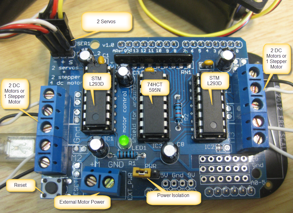
Motor Stepper Servo Shield Details
The Eagle Schematics and layout is available on GitHub here.
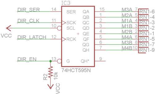
74HCT595N on Arduino Motor Shield
The 74HCT595N on the Arduino Shield is used to drive 8 motor bridge pins (M1A, M1B, M2A, M2B, M3A, B3B, M4A and M4B). It uses the DIR_EN pin to enable the device. The Ardunio Motor shield schematic is using ‘DIR’ as the signals are used to change the motor direction signals. More about this in the next tutorials.
74HCT595 Shifting
To illustrate the shifting of the device, I have connected the device to a logic analyzer:

Probing the 74HCT595N
Below I’m shifting in the value 0x03 on the data/DS pin, with the LSB (Least Significant Bit) first. The data gets shifted into the device on each raising edge of the clock signal. At the raising edge of the latch signal, the data shows up on the output pins D0-D7, where D7 has the least significant bit:

74HCT595N Shift Sequence
If I have the devices chained, then the D7 bit would be shifted into the next device through the ‘chain’ pin.
FRDM-KL25Z Connections
The shift register is connected as below to the FRDM-KL25Z board, as defined by the pin mappings of the shield:
- DIR_SER (Serial Input Pin)/DS => Arduino Header D8 => KL25Z pin 33 => PTA13/TPM1_CH1
- DIR_CLK (Shift Clock)/SHCP => Arduino Header D4 => KL25Z pin 30 => TSI0_CH5/PTA4/I2C1_SDA/TPM0_CH1/NMI_b
- DIR_LATCH (Latch clock)/STCP: => Arduino Header D12 => KL25Z pin 76 => PTD3/SPI0_MISO/UART2_TX/TPM0_CH3/SPI0_MOSI
- DIR_EN (Device Enable)/OE => Arduino Header D7 => KL25Z pin 66 => CMP0_IN3/PTC9/I2C0_SDA/TPM0_CH5
Shift and Latch
The following source demonstrates how to shift a byte into the shift register:
- DS1 is the data register
- SHCP1 is the shift clock register
void HC595_ShiftByte(byte val)
{
  uint8_t i;

  /* precondition: latch pin, data pin and clock pin are all low */
  for(i=0;i<8;i++) { /* shift all the 8 bits */
    /* put data bit */
#if HC595_SHIFT_MSB_FIRST
    if (val&0x80) { /* LSB bit first */
#else /* LSB first */
    if (val&1) { /* LSB bit first */
#endif
      DS1_SetVal();
    } else {
      DS1_ClrVal();
    }
    SHCP1_SetVal(); /* CLK high: data gets transfered into memory */
    DS1_ClrVal(); /* data line low */
    SHCP1_ClrVal(); /* CLK high: data gets transfered into memory */
#if HC595_SHIFT_MSB_FIRST
    val <<= 1; /* next bit */ #else     val >>= 1; /* next bit */
#endif
  }
}
The macro HC595_SHIFT_MSB_FIRST is used to either shift in the most significant bit first or the least significant one first.
The method ShiftByte() only shifts the 8bits, and does not latch them to to the output pins. So I can use several times the ShiftByte() method if I have chained shift registers.
To latch the bits to the output pins, the Latch() method is using the STCP (Store Clock Pin/Latch):
void HC595_Latch(void)<
{
  /* send a latch pulse to show the data on the output pins */
  STCP1_SetVal(); /* set latch to high */
  STCP1_ClrVal(); /* set latch to low */
}
For the above pins (DS1, SHCP1 and STCP1) I can use normal GPIO pins in output mode. Pretty easy 🙂
Processor Expert Component
To make usage of a 74HCT595 really easy, I have created a Processor Expert component for it. It is available on GitHub with instructions here how to download and install the components.
The component has following properties:

74HC595 Properties
It specifies the interfaces for the mandatory Latch, Data and Clock pins. The OE (Output Enable) pin is optional. Depending on the type of HC595 there might be different delays needed for clock and latch, so the component offers to specify a delay in nanoseconds.
The component offers the following methods:
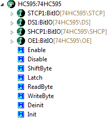
74HC595 Methods
It has Init() and Deinit() methods for driver initialization and de-initialization. ShiftByte() and Latch() are the methods discussed above. Additionally it features to methods:
ReadByte()returns the latched value. For this it uses a cached (local) variable.WriteByte()does the shifting and latching for a single byte in a single method.
Summary
Shift registers are very useful to expand the amount of pins of a microcontroller: with a few pins it is possible to have many more pins. Writing a driver for it is not difficult, and I hope the 74HC595 Processor Expert component even makes things easier. As always: the sources are available on GitHub.
List of Tutorials
- Tutorial: Arduino Motor/Stepper/Servo Shield – Part 1: Servos
- Tutorial: Arduino Motor/Stepper/Servo Shield – Part 2: Timed Servo Moves
- Tutorial: Arduino Motor/Stepper/Servo Shield – Part 3: 74HCT595 Shift Register
Happy Shifting 🙂

Pingback: Tutorial: Arduino Motor/Stepper/Servo Shield – Part 2: Timed Servo Moves | MCU on Eclipse
Pingback: Tutorial: Arduino Motor/Stepper/Servo Shield – Part 1: Servos | MCU on Eclipse
This worked, have you ever done microstepping?
LikeLike
You mean using a stepper motor with that shield? No, that’s on my growing list of things I want to do, but never had time for it 😦
LikeLike
Ok, sure I also have a lot to write but no time as I am experimenting. I am using stepper motors from cdroms to build X-Y platform for application in some kind of imaging that requires shifting. DO you know which connection on the stepper motor shield is DIR for changing direction. I cant find anything about that.
LikeLike
A few links:
http://digital.ni.com/public.nsf/allkb/0AEE7B9AD4B3E04186256ACE005D833B
http://ssecganesh.blogspot.ch/2008/05/identifying-leads-of-unipolar-stepper.html
LikeLike
I am using in my project the same Arduino Motor/Stepper/Servo Shield and I want know if it is possible to change the pin 12
This part of the code in .h
// Arduino pin names for interface to 74HCT595 latch
#define MOTORLATCH 12 // I want change this pin 12 for 0, 1 or 2.
#define MOTORCLK 4
#define MOTORENABLE 7
#define MOTORDATA 8
I want to change the pin 12 for another pin. I want to do it, because in my project I need to use this pin 12. I have free the pins 0, 1 e 2 of the my Arduino.
Help me please!
LikeLike
Hello,
you need to check the schematics of your board if this is possible at all.
Erich
LikeLike
Guys, can anyone send me a simple code to run the dc motor. I tried but not very sure how the ports need to be set. I followed the instruction above to set all the ports for the Shield.
LikeLike
The code is available on GitHub already: https://github.com/ErichStyger/mcuoneclipse/tree/master/Examples/CodeWarrior/FRDM-KL25Z/Freedom_Motor
LikeLike