
The Pololu Zumo chassis is nearly perfect for my needs: it is small and compact, and neatly works with the FRDM-KL25Z board. I’m able to use it for line following or maze solving. But it lacks a position (quadrature) encoder on the wheels which is either very useful or even required for the lecture assignments for my next class. The Pololu Zumo chassis mainly has been designed for Robot-Sumo competitions, where such quadrature sensors are not really needed. Pololu offers optical quadrature sensors for their 42×19 mm wheel which I used in this project. So why not adding these sensors to the Zumo chassis?
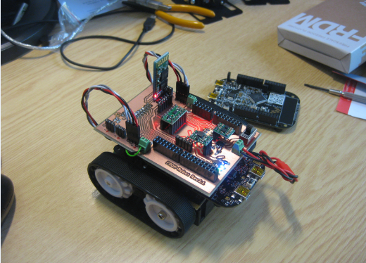
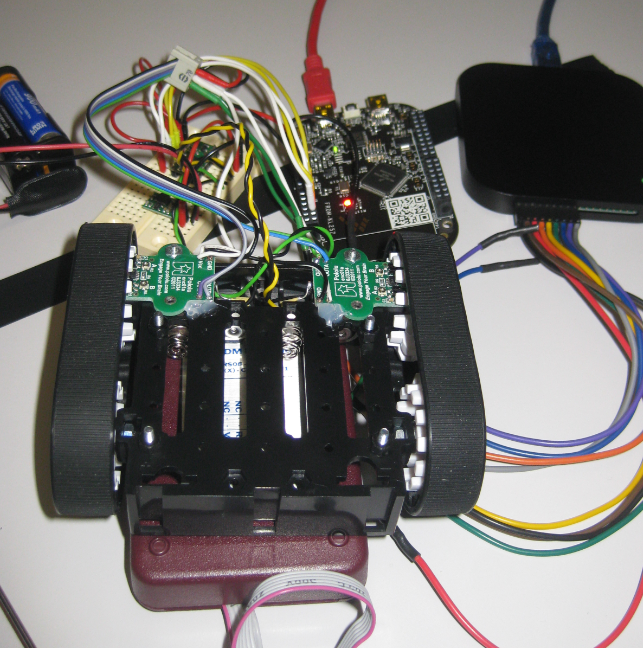
FRDM-Robot with Quadrature Sensors Mounted
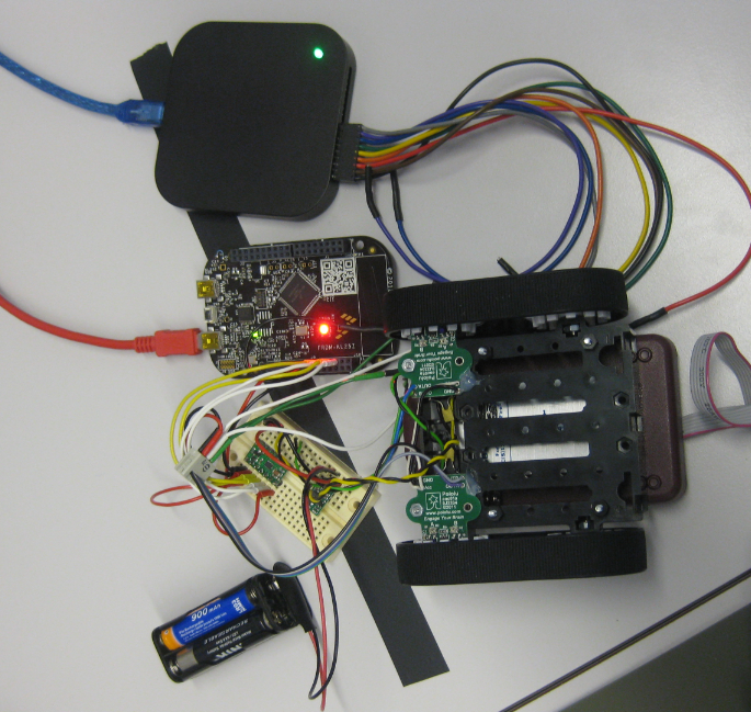
Pololu Zumo Chassis with Encoders
Adjusting Sensor for 3.3V Operation
The FRDM-KL25Z operates with 3.3V logic levels. By default, the Pololu optical encoder are configured to work with 5V supply and logic levels. To change the hardware to 3.3V, the resistor R4 needs to be shortcut:
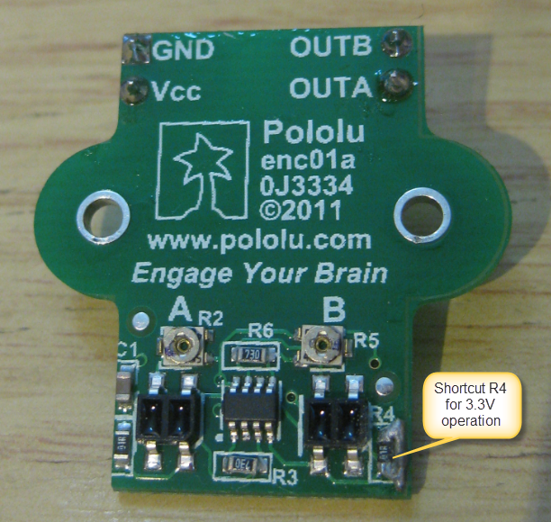
Shortcut R4 on Pololu Encoder Sensor
The preferred way would be to remove the R4 and bridge the footprint. Otherwise you can solder a thin wire over the R4.
❗ The space above R4 with the sensor mounted inside the wheel is very limited. So if you decide to solder a wire, then make sure that it is on the side of the resistor as shown in the image above. Otherwise the wire might touch the wheel.
The sensors are factory trimmed for 5V operation. In a later step we need to trim them for 3.3V.
Mounting the Sensors
The encoders can be fixed with a screw on the front side. As there is no matching hole on the other side, I used hot glue to fix the sensor on the chassis:
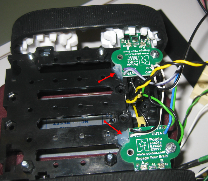
Mounted Encoders
I used a low temperature glue gun (UHU Low Melt LT 110) which already melts at 110° Celsius. This prevents heat damage to the plastic Zumo chassis, although normal hot glue might work too.
UHU Low Melt LT 110
Recalibrating Sensors
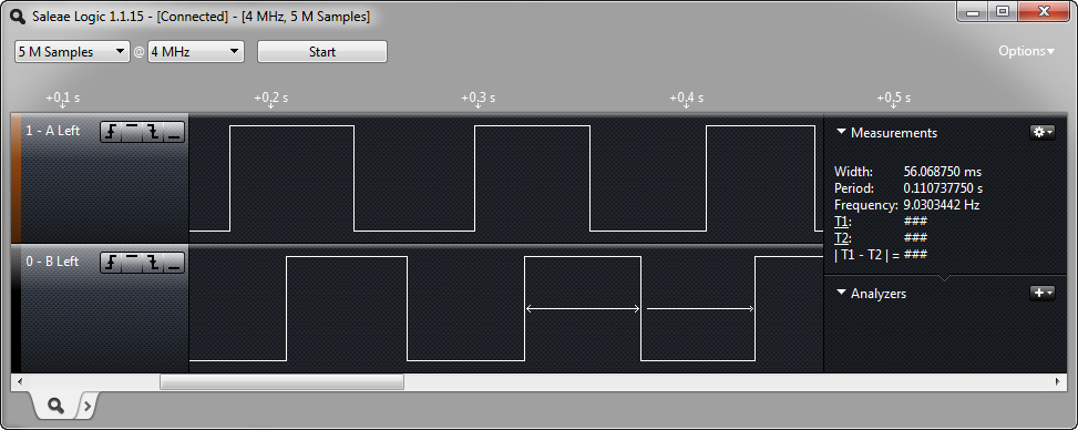
The goal is to have the signal on each channel (A, B) shifted by one quadrant (90°), with the duty equally low and high:
Equally Distributed Quadrature Signal
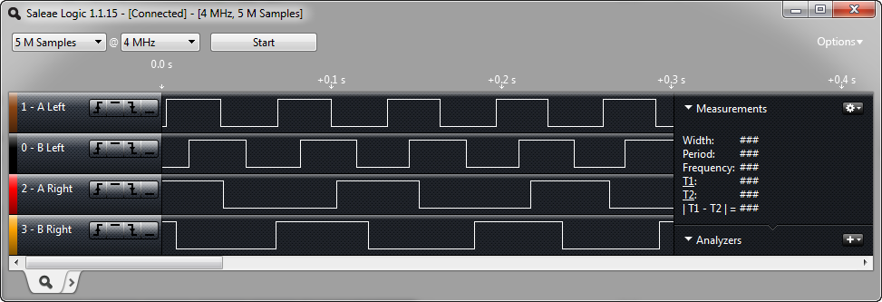
The sensors are factory trimmed for 5V, so we need to change the potentiometer trim values for 3.3V. For this, put the chassis off the ground so the motors can freely run. Hook up a osczilloscope or a logic analyzer to the A/B signals of the encoders:
Logic Analyzer to monitor signals
Use a mini screwdriver to adjust the potentiometer. Be careful not to damage the small potentiometer.
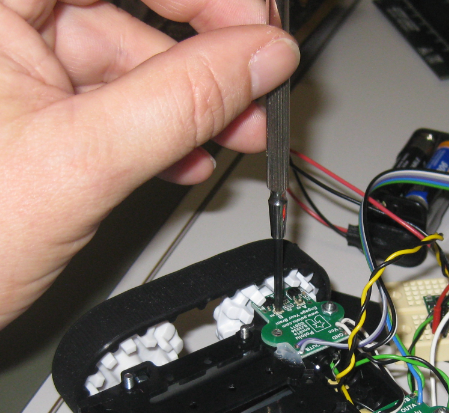
Adjusting with the Potentiometer
If you have no signal on the channel, then turn the potentiometer carefully into one direction until you have a signal. Then tune the signal to get a 50%-50% duty.
Turning the potentiometer clockwise, the duty gets shorter:
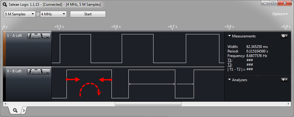
Turn Clockwise to Reduce Duty
Turn the potentiometer counter-clockwise to increase the duty cycle:
Counter Clockwise to Increase Duty
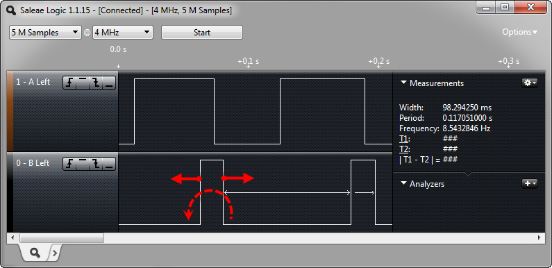
The goal is to have a 50%/50% high/low sequence of the signal. The following shows all four channels after calibration, with the left motor running faster than the right motor:
All Channels Calibrated
Software
I have created a Processor Expert component (QuadCounter, see as well this post) which performs the quadrature signal decoding. The component features a command line/shell interface so I can easily verify the operation of the sensor.
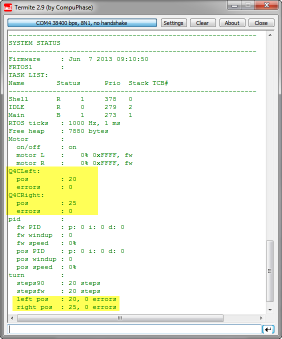
Quadrature Status with Shell
With this, I can verify the proper operation of the sensors.
Chassis Modifications
Because the upper chassis plate conflicts with the quadrature sensors, I had to cut the corners. To show the effect, I have placed an original plate (with the brown protective sheet still on it) below my modified plate:
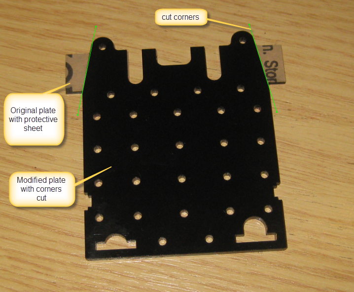
Pololu Zumo Chassis Plate with cut Corners
Battery Holder Adapter
The chassis features a 4 AA battery holder. However, the two battery contacts are very short and designed for the Pololu Arduino Zumo Shield. Because the sensors increase the distance, and the battery contacts need to be attached to something, I used a piece of PC to solder the contacts. To mount the plastic plate, 4 screws with distance holders are used:
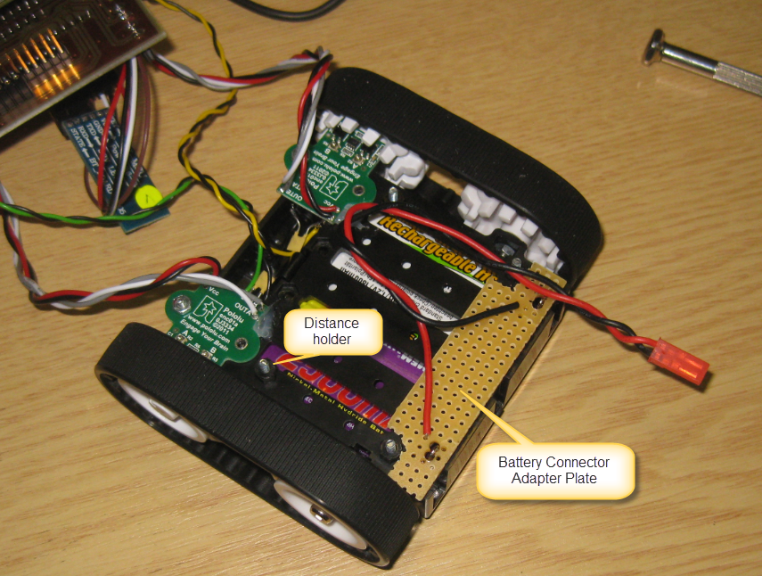
Battery Holder Adapter
💡 I a next revision, I consider to build up a PCB to cover the chassis. Potentially to integrate the quadrature sensors too.
Then to simply put the plastic plate on top of everything:
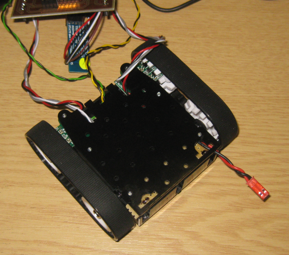
Plate Mounted
With the plate cut coners I still can access the potentiometers if I need to recalibrate them. And I can place the FRDM-KL25Z board on the plastic plate.
FRDM-Robot Motor Shield
The two quadrature sensors, the two motors and the battery power gets connected to the FRDM-Robot shield (FRDM-Robot Rev2.1 PCB created by Andrin Tuor for this project):
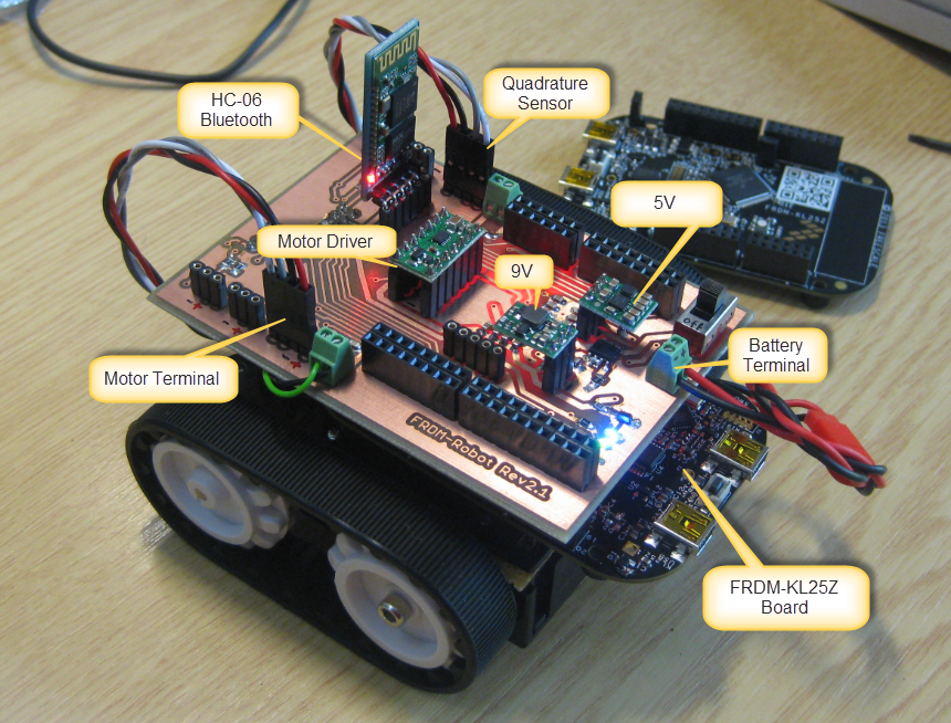
FRDM-Robot Rev2.1 (correction: the motor terminal is the green two wire connector with screws)
Summary
With a few modifications, some glue and wiring I’m able to extend the Pololu Zumo chassis with position sensors. This allows me to track and measure the way, plus makes the turns more reliable. Pololu indicates that the sensors are not designed for the Zumo chassis, and they warn about that it might need extra protection from light, as the sensors are pointing to the ceiling, and the light might not be blocked correctly inside the wheel. So far I have not seen any problems. And if so, it would not be a big deal to cover the sensor to avoid external light exposure.
Happy Quadrating 🙂

Pingback: Tutorial: Ultra Low Cost 2.4 GHz Wireless Transceiver with the FRDM Board | MCU on Eclipse
I like it! Also thanks for posted the signal tweaking and measuring notes. I haven’t done much with encoders, this will be helpful.
I am attempting this as well, however I intended to include the Zumo Shield and Reflectance sensor. However rather then driven the shield with an Arduino, I am using a Parallax Propeller on the Prop ASC+ board that is compatible with shields but has the 8 parallel core board.
Biggest issues is the shield’s reflectance female header mounted on the shield is getting in the way of the. I have a couple of ideas to work around this, however not sure yet which route I will take…
LikeLike
Hi Matt,
not sure if you have seen it: I used the Zumo shield as well, see
The header itself was not an issue, but the fact that my board has 3.3V signal levels, but the reflectance PCB needs 5V. See above post how I have solved it. Adding the shield on top of the encoder is a problem as this means the shield is on a higher position than originally designed: you would need to extend the reflectance header, and as well think about how to extend the battery contacts so they reach the shield.
I hope this helps, and happy zumoing 🙂
LikeLike
Pingback: A new Freedom Board: FRDM-KL46Z | MCU on Eclipse
Pingback: Mini Sumo Robot Competition running with FRDM-KL25Z | MCU on Eclipse
Pingback: Mini Sumo Robot with Proximity Sensors | MCU on Eclipse
Pingback: Processing the Pololu Motor Shaft Encoders | MCU on Eclipse
Pingback: New Zumo Robot PCB’s Arrived! | MCU on Eclipse
Hi Erich,
I am using the Quadrature Decoder of the FTM – however I only use the init_FTM bean and access the registers directly.
Now I need to also get the value of the two input bits (phaseA and phaseB) for use in auto-detecting presence.
I tried ‘bits=(GPIOB_PDIR&0x0600)>>17)&0x3;’
to get PTB17 and PTB18 into the varible ‘bits’, but it doesn’t seem to work right (always 0)
I can see the bits I want with the EmbSys registers window GPIO->PTB->PDIR , and they change like I want when I move the encoder, but how do I pull them into a varible?
Brynn
LikeLike
Ugg. clearly I need to and with 0x060000 and not 0x0600. but it still doesnt seem to work. How do I pull the value of those bits out without messing with the FTM quadrature setup?
LikeLike
I’m using normal sampling to get the bits as GPIO bits: way easier than messing up with the FTM (I understand you have configured it as FTM?).
Is the PDIR not a 16bit register? so ‘>>17’ would make it zero?
LikeLike
The reference manual says it is a 32 bit register. it also says that if it is not configured for digital it will read 0, but I can see the bits I want toggleing like they should with the debugger – but I am having trouble getting the bits in under program control
this is what it says:
Port Data Input
Reads 0 at the unimplemented pins for a particular device. Pins that are not configured for a digital
function read 0. If the Port Control and Interrupt module is disabled, then the corresponding bit in PDIR
does not update.
400F_F050 Port Data Input Register (GPIOB_PDIR) 32 R 0000_0000h 50.2.5/1381
LikeLike
I think you might have a problem how your GPIOB_PDIR is declared (macro)?
Here is how I read it:
#define QuadCounter_GET_C1_PIN_LEFT()      (McuGPIO_GetValue(C1_Left))

#define QuadCounter_GET_C1_C2_PINS_LEFT()               ((QuadCounter_GET_C1_PIN_LEFT()?2:0)|(QuadCounter_GET_C2_PIN_LEFT()?1:0))
bool McuGPIO_GetValue(McuGPIO_Handle_t gpio) {

  return McuGPIO_IsHigh(gpio);

}
which calls:
bool McuGPIO_IsHigh(McuGPIO_Handle_t gpio) {

  assert(gpio!=NULL);

  McuGPIO_t *pin = (McuGPIO_t*)gpio;
#if McuLib_CONFIG_CPU_IS_KINETIS
return GPIO_PinRead(pin->hw.gpio, pin->hw.pin)!=0;
#elif McuLib_CONFIG_CPU_IS_LPC
return GPIO_PinRead(pin->hw.gpio, pin->hw.port, pin->hw.pin)!=0;
#elif McuLib_CONFIG_CPU_IS_IMXRT
return GPIO_PinRead(pin->hw.gpio, pin->hw.pin)!=0;
#endif
return false;
}
which uses the SDK:
static inline uint32_t GPIO_PinRead(GPIO_Type *base, uint32_t pin)

{

    return (((base->PDIR) >> pin) & 0x01U);

}
I have setup the pins like this:
static void QuadCounter_PinInit(void) {

  McuGPIO_Config_t gpioConfig;
/*
* Left: PTC16, PTC17
* Right: PTC10, PTC11
*/
McuGPIO_GetDefaultConfig(&gpioConfig);
gpioConfig.hw.gpio = GPIOC;
gpioConfig.hw.port = PORTC;
gpioConfig.hw.pin = 16;
gpioConfig.isInput = true;
C1_Left = McuGPIO_InitGPIO(&gpioConfig);
gpioConfig.hw.pin = 17;
C2_Left = McuGPIO_InitGPIO(&gpioConfig);
gpioConfig.hw.pin = 10;
C1_Right = McuGPIO_InitGPIO(&gpioConfig);
gpioConfig.hw.pin = 11;
C2_Right = McuGPIO_InitGPIO(&gpioConfig);
}
Erich
LikeLike