
In “Unboxing the Freescale FRDM-KL43Z Board” I was using the FRDM-KL43Z board the first time. The FRDM-KL43Z board has an on-board debug interface (Kinetis K20, OpenSDA). In this post I show how to use the FRDM-KL43Z board to debug another ARM board.

FRDM-KL43Z Board debugging custom (tinyK20) Board
Outline
In this post I show how to use a normal Freescale Freedom (FRDM) board into a SWD (Single Wire Debug) debugging probe to potentially debug any other ARM Cortex core supporting SWD. I’m using here the FRDM-KL43Z board, but the other Freescale Freedom boards are very similar.
Hardware Setup
There are two things involved to use the board as a debugging probe:
- J18: This is a header to separate the trace between the OpenSDA/K20.
- J11: This is a 2×5 SWD header for standard ARM 10pin

SWD Connector Schematic on FRDM-KL43Z (Source: Freescale FRDM-KL43Z Schematics)
Both J11 and J18 are *not* populated on the board.

J11 SWD and J18 on FRDM-KL43Z Board

FRDM-KL43Z J18 and J11 on Back Side of Board
I need to have the following available parts:
- 1×2 Jumper and Header for J18 (you probably have a few on your desk?)
- 2×5 SWD Header for J11 (SAMTEC – FTS-105-01-L-D, e.g. 1667728)
- Standard ARM SWD/JTAG cable (e.g. 1667659), or borrow it from a P&E Multilink or Segger J-Link
Beside of that: a sharp knife and a soldering iron (small soldering tip) with solder wire 🙂
Use a sharp knife to cut the trace on the backside of J18:

Cut Trace of J18
Solder the 1×2 header on J18:

Populated J18
Solder the 2×5 SWD/JTAG header on J11:
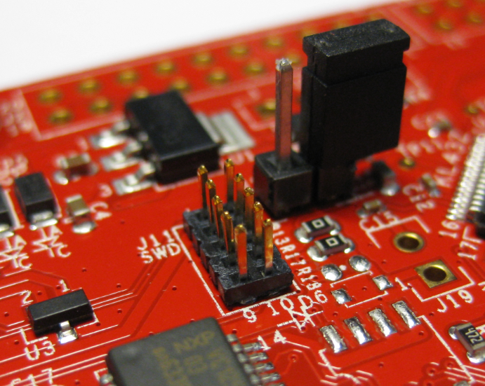
Populated J11
To debug another board, install the 10pin flat cable (Pin 1 of J11 matching the red cable) and have the jumper on J18 removed ( J18 is open):
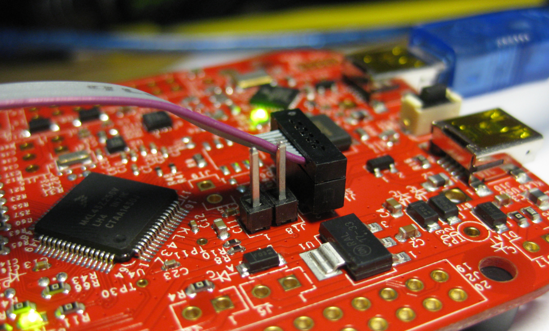
J11 and J18 to debug another board
Connect the other side of the cable to the target board:

Connected Boards
OpenSDA Debug Firmware
With the default (P&E) firmware on the FRDM-KL43Z it is *not* possible to debug another processor, except the device on the FRDM board itself.
Instructions how to update the firmware are explained here: “Illustrated Step-by-Step Instructions: Updating the Freescale Freedom Board Firmware”
There are the following other debug firmware files available for OpenSDA (with links to articles and firmware files):
- Segger J-Link, see “Freedom Board with Segger OpenSDA Debug Firmware“
- CMSIS-DAP with OpenOCD: see “CMSIS-DAP with IAR and the KL25Z Freedom Board“
- USBDM: see “Debug External Processors with USBDM and Freedom Board“
The CMSIS-DAP and USBDM firmware files are open source and can be used without restrictions. The Segger J-Link has the following TERMS OF USE:
TERMS OF USE
1) The firmware is only to be used with Freescale target devices. Using it with other devices is prohibited and illegal.
2) The firmware is for use with evaluation boards only. It is not for use with custom hardware.
3) The firmware may only be used for development and/or evaluation purposes. It may not be used for production purposes.
4) The firmware is made available without any warranty and without support.
5) The firmware may be used with the OpenSDA platform only.
So I can use it to debug another FRDM Board:

Debugging FRDM-KL25Z with FRDM-KL43Z Board
Updating the OpenSDA Firmware
💡 In case you want to use the board with Windows 8, 10 or Mac, you need to have first a Windows 7 machine to update the bootloader. See “Illustrated Step-by-Step Instructions: Updating the Freescale Freedom Board Firmware“.
To update the OpenSDA firmware of the FRDM board:
- Power the board through the USB port labeled ‘SDA’, while having the Reset (RST) button pressed.
- Green LED near K20/USB port blinks with about 2 Hz
- The board enumerates as ‘BOOTLOADER’ device (MSD, disk drive) on the host.
- Copy the firmware file to the BOOTLOADER device.
- Repower the board normally.
💡 If the ‘copy’ operation fails or does not work: use the command prompt, additionally make sure you don’t have an issue with firewalls or virus scanners.
With that, the FRDM board is like a normal debug probe and can be used as such.
Summary
It requires some soldering skills, a little extra hardware and a firmware file to turn a FRDM board into a normal debugging probe. I still recommend to use normal SWD/JTAG debug probes e.g. from Segger or P&E, as they were able to recover and work with all of my boards (especially unsecuring devices), while the FRDM board solution works, it is not that powerful. But as a quick and cheap solution it works fine.
Happy Debugging 🙂
Links
- OpenSDA in Freescale Community
- Using the Freedom Board as SWD Programmer
- Debug External Processors with USBDM and Freedom Board
- Completing the FRDM-KL25Z Board

Why is the board(FRDM-KL43Z) ? Also on board FRDM-K64F, FRDM-K22F ………..
LikeLike
… Thank you for the important post
Today, very helpful.
LikeLike
Briskets are equally important 🙂
LikeLike
Yes, as noted, the same approach works for other FRDM boards. But FRDM-K64F and FRDM-K22F are using OpenSDAv2: same concept, different bootloader. But should work too (have not tried myself). I have selected FRDM-KL43Z as it is less expensive than K64F and K22F, and I see the KL43Z starting to get as popular as the FRDM-KL25Z (which currently is probably the most popular FRDM board).
LikeLike
Erich,
Another source for the 10 Pin headers is Mouser: 649-221111-00010T4LF.
I add these to all the target CPU SWD on my FRDM-xxxx boards so I can debug with my J-Links.
Mouser also has a nice ribbon cable: 855-M50-9100542
It is 150mm long. They also stock a 300mm version too. I have tried both and they work fine with my two J-Links.
Thanks for all your great work.
LikeLike
Pingback: SWD Debugging the FRDM-KL43Z | MCU on Eclipse
Hi Erich,
Can we use the FRDM in a similar way on Kinetis Design Studio?
LikeLike
Yes, that works with KDS.
LikeLike
Hello Erich,
I’m sorry if the procedure to attach an external target is a little difficult. When designing openSDA hardware, I wanted to make its output able to be used with a different target, but FRDM boards were required to work with a very tight budget, so having no headers at all was requested and I came up with the idea to leave unplaced footprints and solder shorts.
Regards,
Rafael.
LikeLike
Hi Raphael,
so you designed that board? Nice to meet you :-). It is understood that the primary purpose of the board is to show and debug the onboard device. having parts and headers not populated is a common way to save costs: footprints and solder shorts are good to me. It is just that other vendors either do the same, or have more parts populated than Freescale.
LikeLike
Hello Erich,
I designed FRDM concept with FRDM-KL25 board and openSDA. FRDM-KL25z bill of materials was required to cost around $5USD, including PCB; even USB routing technique is state of the art so we could maintain target impedance with a cost effective PCB (I mean uber-cheap). Actually, I had the opportunity to publish a paper about that.
I’m a follower of your blog, I’m not very used to software and I would like to make a full app with FRDM boards. Nevertheless I often recommend my students to take a look at it.
Un saludo,
Rafael.
LikeLike
Hi Rafael,
interesting, my thinking was that the FRDM board even in high volume will be at a cost above $5 (my guess is around $10). Is that paper you mention public somewhere?
Probably you have seen https://mcuoneclipse.com/2015/11/28/a-raspberry-pi-for-5-what-are-your-decision-factors/: As for the $5 for the Raspberry Pi Zero: alone the memory and the ARM device should be around $5 in volume, not to count in all the other parts (but not that many). It is interesting to see what is possible.
LikeLike
Hello Erich, paper is available here: http://ieeexplore.ieee.org/xpl/articleDetails.jsp?arnumber=7102514 I can share you a copy in case you don’t have access to IEEE.
Yes, I saw the $5 computer, and I’m glad my uber cheap concept went in the right direction. Are you going to post how to start with it? if yes then I should definitely order one for christmas.
LikeLike
Hi Raphael,
yes, I have access to IEEE :-), thanks for passing that link. Interesting paper, indeed. As for the Raspberry Pi Zero for $5: I have ordered one, and if UPS is right, I should have it in my hand by today or tomorrow. I won’t have probably time to write a lot about it in the next two weeks, but hey: Christmas vacation is coming up 🙂
LikeLike
Pingback: How to Recover the OpenSDA V2.x Bootloader | MCU on Eclipse
Pingback: Using the LPCXpresso V2/V3 Boards to Debug an external Board | MCU on Eclipse
Hello,
Can i use same FRDM KL43Z board to program/debug custom made MK10DN64 board using SWD interface. What changes are to be made.
Thanks
LikeLike
Yes, you can use the FRDM-KL43Z for this. Follow the instructions in this article.
LikeLike
Thank you,
So i need to separate the trace of J18 and use J11 SWD for programming and Debugging. Which OpenSDA firmware i need to on frdm board for using with external MK10DN64.
LikeLike
Yes, as described in this article.
As for the firmware, the P&E one does not allow you to program anything different than the device on the board. The licensing terms for Segger do not allow you debug your own board.
So you have use the CMSIS-DAP firmware.
LikeLiked by 1 person
and MK10DN64 runs at 50MHz, is there any problem
LikeLike
No, there should be no problem, as long as that device is supported by the debug connection (CMSIS-DAP) you are going to use.
LikeLike
Can you give more information on CMSIS-DAP firmware example, i want both programming and debugging functionalities.
LikeLike
For CMSIS-DAP, see https://mcuoneclipse.com/2015/03/22/openocdcmsis-dap-debugging-with-eclipse-and-without-an-ide/
LikeLike
I am using codewarrior for development
LikeLike
Consider moving up to Kinetis Design Studio or MCUXpresso IDE, as you have more and better choices.
For CodeWarrior I had used USBD (see https://mcuoneclipse.com/2013/04/27/debug-external-processors-with-usbdm-and-freedom-board/), but that did not work any more on my Windows 10 machine. You can give it a try.
LikeLike
so on overall, i am using windows 7 machine with codewarrior. So i can use FRDM MKL43Z board to program and debug MK10DN64 external custom board by making changes on J18 and J11 to use SWD interface. Use USBDM connection on setup. But i am still confused about the bootloader fimware, which should be there on the FRDM board.
LikeLiked by 1 person
You cannot change the bootloader on the FRDM-KL43Z as the bootloader is secured with mass erase disabled.
But do you think it is really worthwile to do all this work with the FRDM-KL43Z? You get an educational Segger J-Link EDU Mini for Euro 20, a fully professional tool which works for any IDE?
Have you considered this?
LikeLike
can i use this https://www.segger.com/products/debug-probes/j-link/models/j-link-edu-mini/ for programming the MK10DN64 also
LikeLike
yes
LikeLike
hi, Erich i have developed a MKL25Z128VFM4 custom board for a iot, but when i’m trying to debug in CodeWarrior appears a message like this “No source available for “0xFFFFFFFE (0xFFFFFFFE)() ” but i have modified the linker file to other address like say in the memory Map but it still appears, i’m using the FRDM-KL25Z as openSDA to debug that. Hope you can help me thanks.
LikeLike
Does this only appear at the startup code or for every place in the application?
There could be several reasons for this. One obvious one would be if you have generated the application without debug information?
LikeLike
It’s appear in the startup code and doesn’t let me advance, yes, i run without modify the debug information, only with codewarrior default configuration for the FRDM-KL25Z, where can i find a troubleshoter for indentify if my board is wrong. or what config files i should modify, thanks
LikeLike
If you can debug the same application using a normal board/debug probe just fine, then there is nothing wrong with your host/application/settings, but a problem with your custom board.
While using a FRDM board works technically to debug another one, I really recommend that you spend the $20 for a J-Link EDU min or LPC-Link2 (there seems a new McuLink coming out for just $10, see my recent articles). The reason is that electrically a dedicated debug probe is much more robust and versatile compared using a FRDM board.
LikeLike