To build an application for a modern microcontroller today is not a simple thing. Well, it depends what ‘simple’ means. But compared to the ‘old days of 8bit micro controllers’ (which are still in use!) developing for a complex 32bit device is definitely a different thing. Not only the complexity has changed, but as well the breath of tools and helpers. In my view, the only constant is ‘change’, and I have changed the way how to develop several times in my career. In this post I present several different techniques I’m using in my development.

Processor Expert CPU View
Overview
This is a kind of different post than I usually do: I have been asked by several readers if I could write an overview and introduction about how to develop an embedded application: so not a deep dive down to the bits, but more about a general approach and and about the concepts. Let me know what you think…
When I’m developing an embedded application, I’m using different tools, techniques and helpers to get it done. I go through the general thought process, and then going into different abstraction and implementation levels. Most of my projects are using parts from Freescale (soon to be NXP?), and I’ll show examples from other vendors I’m using too.
Where to focus on?
What if I have to build an embedded application like a small HTTP web server with SD card, USB and Serial connectivity and acting as a gateway to a WSN (Wireless Sensor Network)? Drawing a basic file/module/block diagram could be something like this:
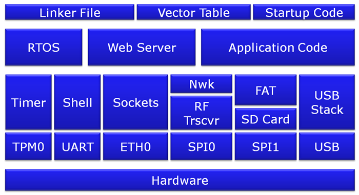
Application Block Diagram
So it uses some hardware (e.g. an ARM Cortex-M or similar), and choosing that one is a complex process alone. My application needs some low-level drivers like UART, SPI, USB and high-level drivers on top of it. In most of my applications today I’m using a real time operating system or kernel of some kind, because it adds a lot of flexibility. I’ll need to run a web server and to write the application logic. From the build tool environment, I need things like linker script files, low-level vector table(s) and the library/startup code.
There are many ways to start something like this. From off-the-shelf solutions to using Embedded Linux down to a custom microcontroller solution. It all will depend on the requirements, the time and money I have available.
The question I have to ask myself: what I’m going to ‘make’, and what I’m going to ‘buy’? Or: where should I invest my time? Which blocks I can re-use from other projects, or from somewhere else, which blocks do I have to create?
‘Buy’ it?
There are some parts in the system which I think I have to ‘buy’ it: I don’t want to make my version of a real-time operating system: there are plenty of options available there, e.g. FreeRTOS. Same for other ‘standard’ drivers or middle ware: USB, web server, TCP/IP stack: they are fairly common or available in the open source space. But even if they are ‘free of charge’, it means that I still have to ‘pay’ a price: time to evaluate, time to integrate, time to learn it. A few points I consider for the ‘buy’ parts:
- What are the licensing terms and conditions? Take this seriously, as otherwise impact might be huge. I don’t want contaminate my sources.
- Payment, if any? Per unit, per project, or something else? Many IP blocks are free for hobby or educational usage only.
- Costs and time for integration? How easy is to learn and use it?
- Where can you get help? Maintenance contract? Support and upgrade policy? Communities?
- Can knowledge/experience leveraged from or to other projects or from peers?
- If it is something new: any community opinions? Is it actively maintained?
I try to re-use things from earlier projects as much as possible.
‘Build’ it?
Other parts of the system might not be readily available, or might not meet the requirements. For example I need to use low power modes, and nothing is available, or the driver from the vendor does not implement it. So I need to invest time here too. I need to carefully check the data sheet of the device to understand the hardware, bits and pins. I need to come up with a concept/architecture for that part. I need to write the source files with interface and implementation files. I need to test it and finally integrate it into my application. This might take days to weeks, depending on the complexity.
Typical things I need to find out are:
- How does this peripheral work? Which bits do I need to set/clear/modify? In which sequence?
- Is there any pin muxing? Does the block have an impact on other peripherals?
- How do I configure the clocks? How to work with low power modes?
- What is needed in the interface? Which functions are needed by the application?
Basic information about this is provided in the RM (Reference Manual) of the device. It now depends how much experience I have with that device. But that easily can end up in many PDF pages I have to read. For example, the Freescale KL25Z is a rather simple and small ARM (Cortex-M0+) microcontroller compared to others. Still, the RM for it is more than 800 pages, and does *not* cover the ARM core itself! Adding everything to understand the device, and I’m in the range of thousands of pages.
So it would be good if there would be some helpers for me to write that code? I need helpers from how to set some special modes, how to initialize the muxing, the pins and the peripherals, I need startup code/linker files, software drivers up to middleware stacks.
Helpers to get it done
There are many ways to get it done. In the next sections I describe what I’m typically using these days, with the pros and cons, for your own inspiration and consideration.
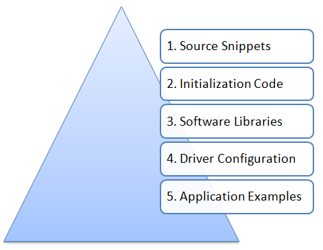
Application Development Helper Pyramid
1. Source Snippets
Sometimes all what I need is “how to enable pull-ups on a pin” or “how to disable the MMU”. What I’m looking for is for a few lines (snippets) of code. A common source for this information are discussion forums, mainly vendor specific forums like from Freescale, TI or NXP to name a few vendor specific ones. I search directly in the forums, or use an internet search machine to find what I’m looking for.
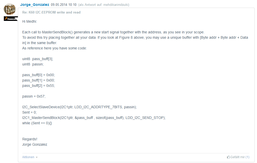
Source Snippet in Community (Freescale)
💡 I have ’email alerts’ enabled on many forums: that gives me a bunch of emails every day, but on the other side often someone posting a question or even a solution I’m interested in it as well.
StackOverflow can be a good resource too, especially for the more generic kind of questions. If I cannot find anything, then I ask a question in a forum. The more specific the question, the better. But I need to be prepared that my question does not get answered, or it might take very long.
💡 I found the ‘search’ functions in the communities usually are not working well. I prefer to use normal search engines like ‘google’. To search in a specif forum, I use the forum name in the search text, e.g. ‘e2e msp430 low power mode exit’
As for searching small code snippets, STMicroelectronics offers collections of snippets in a dedicated STM32Snippets Package:
/**   * @brief  This function enables the peripheral clocks on GPIO ports C,   *         configures the Green LED pin on GPIO PC9,   *         configures the orange LED pin on GPIO PC8,   *         and enables GPIO clock   * @param  None   * @retval None   */ __INLINE void ConfigureGPIO(void) {   /* (1) Enable the peripheral clock of GPIOC */   /* (2) Reset the mode and select output mode on GPIOC pin 8 and 9 */   RCC->AHBENR |= RCC_AHBENR_GPIOCEN;  /* (1) */   GPIOC->MODER = (GPIOC->MODER & ~(GPIO_MODER_MODER8 | GPIO_MODER_MODER9))\                | (GPIO_MODER_MODER8_0 | GPIO_MODER_MODER9_0);  /* (2) */ }Frequently I use Freescale’s Processor Expert to provide me snippets like this:
/* Enable device clock gate */ /* SIM_SCGC5: PORTB=1 */ SIM_SCGC5 |= SIM_SCGC5_PORTB_MASK;Independently if I’m using code generation tools, I can use them to my advantage and ‘peek over their shoulders’ to see how I could things get done.
💡 I describe later how I’m using code generation tools. But the ability to ‘produce example (and working!) code on demand very valuable. I do not have to use the full code, but it gives me the needed snippets I need.
Snippets: Pros and Cons
Snippets are very simple and very efficient. And there is no or minimal learning time (if you are an expert on the device already). They typically do not come with an explanation or the ‘why’, so I need to understand deeply the device and peripherals of the device. They are very device specific and not portable to a different device. And I depend on if I can find it (on the internet) or on a vendor who provides me the snippet I need.
In my view the snippets are a great way for the experts who already know pretty much everything. Snippets provide crucial level of ‘bit level detail’ which might not be present or clear in the reference manual. Frequently I use code generation tools like Processor Expert to have the snippets created for me.
| Pros | Cons |
| Simple, very easy to integrate | Device specific, not portable |
| Minimal learning time | Might or might not exist |
2. Initialization Code
Snippets are a great resource, but they typically only cover a small part of a device like setting the baud rate or how to exit a low power mode. But how to configure and initialize the peripheral? Here again, the Reference Manual is a great resource. Below is a Reference Manual extract (Freescale KL25Z device):
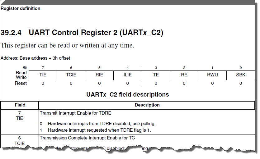
UART Register (Source: Freescale KL25Z RM)
Another approach I’m using frequently (if I’m familiar with the device or device family) is to use the debugger with a register detail viewer. For example I can use the Eclipse EmbSysRegister view to inspect and play with the register values:

FTM Register Settings
I can read this (and more pages) to have an understanding of that peripheral, then write some C/C++ code to set the right bits. Or I can use a tool to provide that initialization source code to me. E.g. to configure the UART0 for 38400 baud or setting up an I2C peripheral for 100 kHz clock and to configure the necessary pins. What I need is an Init() function to make all the settings: configuring the pins (muxing), enabling any clock gates and setting the peripheral registers.
To do this, many vendors have utilities to help me with this. For example STMicroelectronics has a Clock Configurator:
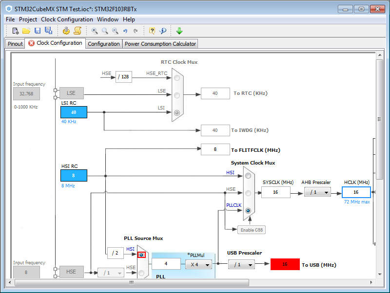
Clock Configuration in STM32Cube
They typically offer kind of ‘cpu package view’ where I can select and configure the pins. Here is the ‘Configurator’ Eclipse perspetive of Simplicity Studio (Silicon Labs):

Configurator in Simplicity Studio (Silicon Labs)
Below is an example of Texas Instrument’s Grace. It is either integrated into Code Composer Studio (CCS) or can be used as a standalone tool (it is a stripped down Eclipse tool then):
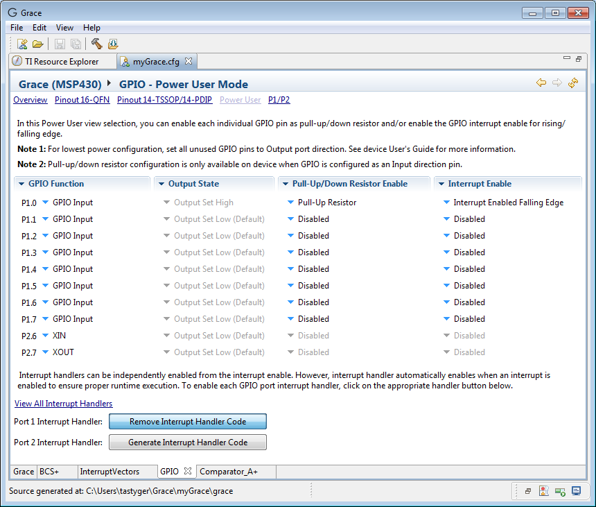
Grace (Texas Instruments)
Based on the configuration, it generates code like this:
/*  *  ======== GPIO_graceInit ========  *  Initialize MSP430 General Purpose Input Output Ports  *  *  The GPIO registers should be set in a specific order:  *     PxOUT  *     PxSEL or PxSELx  *     PxDIR  *     PxREN  *     PxIES  *     PxIFG  *     PxIE  *  *     This will ensure that:  *         - IFG doesn't get set by manipulating the pin function, edge  *           select, and pull-up/down resistor functionalities (see  *           Section 8.2.6 of the MSP430 User's manual)  *         - Glitch-free setup (configuring the OUT register _before_  *           setting the pin direction)  *         - Pull-up/pull-down resistor enable with the correct direction  *           (.up. vs. .down.)  */ void GPIO_graceInit(void) {     /* USER CODE START (section: GPIO_graceInit_prologue) */     /* User initialization code */     /* USER CODE END (section: GPIO_graceInit_prologue) */     /* Port 1 Output Register */     P1OUT = BIT0;     /* Port 1 Direction Register */     P1DIR = 0;     /* Port 1 Resistor Enable Register */     P1REN = BIT0;     /* Port 1 Interrupt Edge Select Register */     P1IES = BIT0;     /* Port 1 Interrupt Flag Register */     P1IFG = 0;     /* Port 1 Interrupt Enable Register */     P1IE = BIT0;     /* Port 2 Output Register */     P2OUT = 0;     /* Port 2 Direction Register */     P2DIR = 0;     /* Port 2 Interrupt Edge Select Register */     P2IES = 0;     /* Port 2 Interrupt Flag Register */     P2IFG = 0;     /* USER CODE START (section: GPIO_graceInit_epilogue) */     /* User code */     /* USER CODE END (section: GPIO_graceInit_epilogue) */ }Below is the PinMux utility from NXP:
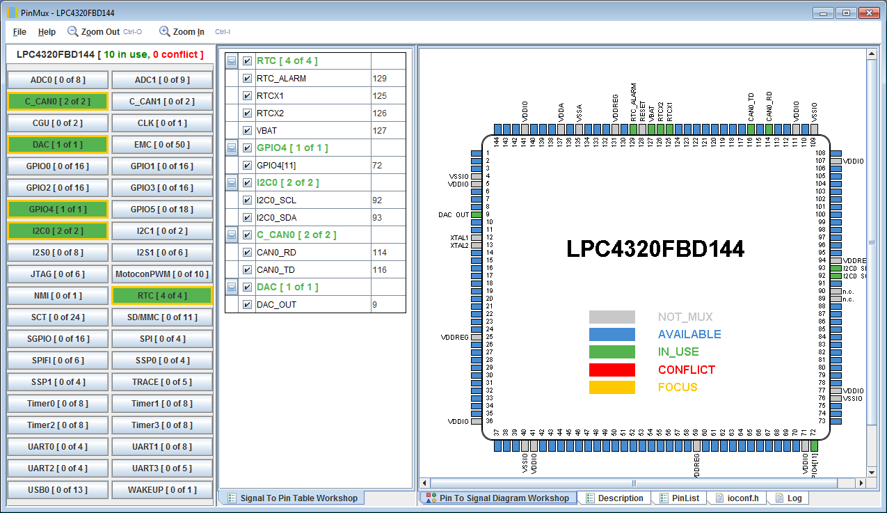
Pin Muxing Utility (NXP)
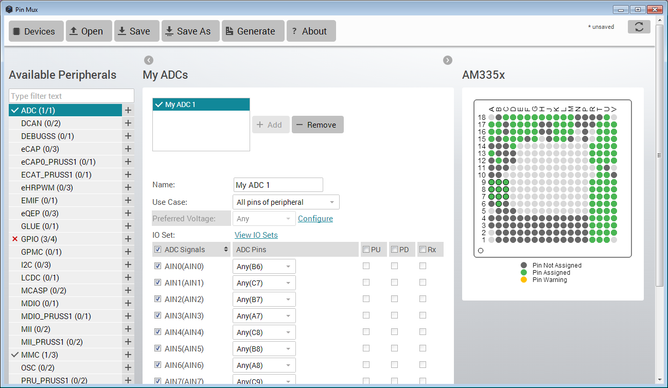
Texas Instrument has a similar utility which runs either locally on the PC or in the Cloud (web based):
Pin Mux (Texas Instrument)
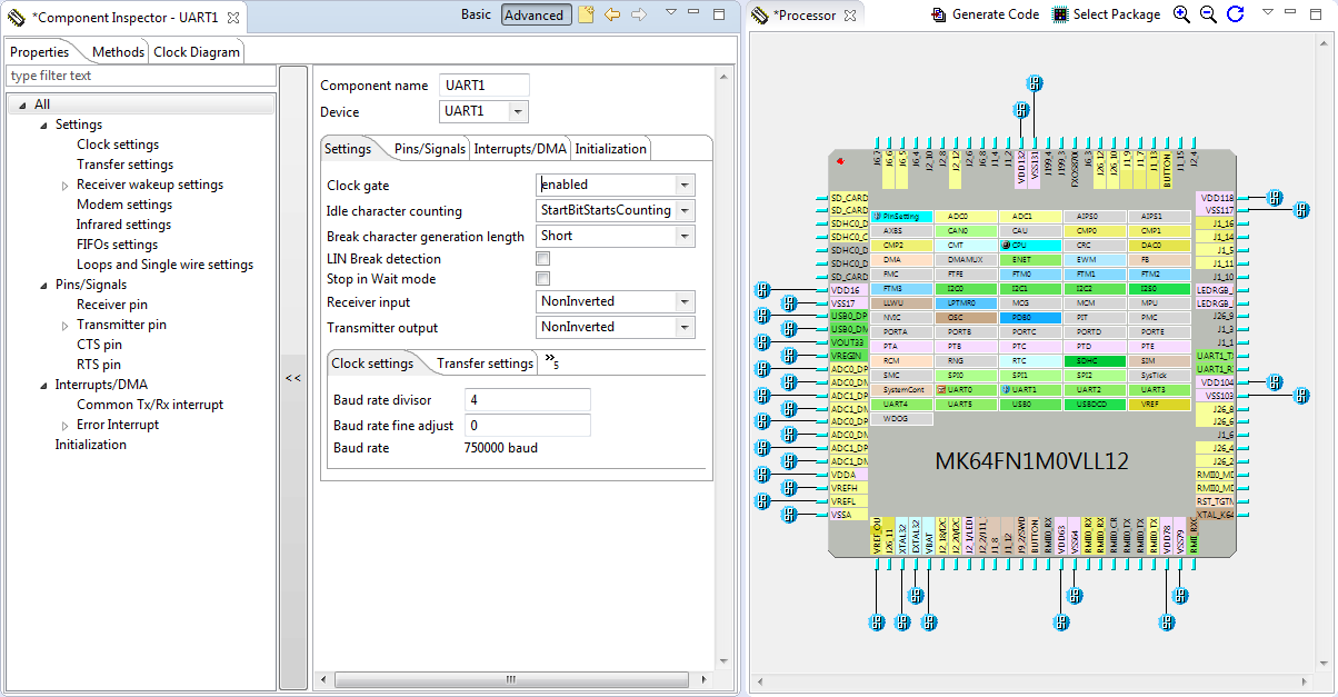
Processor Expert has ‘Init’ components where for example I can initialize the UART: Graphically I select the device, configure the settings and it will create the initialization code for me:
Processor Expert Initialization Tool (Freescale): UART Initialization
In essence, these tools are a ‘graphical’ front end of the reference manual. I still need to understand the mechanics, but do not remember the individual bits to make it happen. Additionally these tools are usually much better describing and checking the constraints and possible conflicts of a setting. For example the tool warns me if I use an invalid configuration.
These tools all generate/provide some kind of source and header files which then I can use in the application code. The application then calls something like InitUART() or similar to use that code. Below is an example of code Device Initialization code provided with Processor Expert:
/* ** =================================================================== ** Method : UART0_Init (component Init_UART) ** Description : ** This method initializes registers of the UART module ** according to the Peripheral Initialization settings. ** Call this method in user code to initialize the module. By ** default, the method is called by PE automatically; see "Call ** Init method" property of the component for more details. ** Parameters : None ** Returns : Nothing ** =================================================================== */ void UART0_Init(void) { /* UART0_C2: TIE=0,TCIE=0,RIE=0,ILIE=0,TE=0,RE=0,RWU=0,SBK=0 */ UART0_C2 = 0x00U; /* UART0_BDH: LBKDIE=0,RXEDGIE=0,SBNS=0,SBR=0 */ UART0_BDH = UART0_BDH_SBR(0x00); /* UART0_BDL: SBR=4 */ UART0_BDL = UART0_BDL_SBR(0x04); /* UART0_MA1: MA=0 */ UART0_MA1 = UART0_MA1_MA(0x00); /* UART0_MA2: MA=0 */ UART0_MA2 = UART0_MA2_MA(0x00); /* UART0_C4: MAEN1=0,MAEN2=0,M10=0,OSR=0x0F */ UART0_C4 = UART0_C4_OSR(0x0F); /* UART0_C1: LOOPS=0,DOZEEN=0,RSRC=0,M=0,WAKE=0,ILT=0,PE=0,PT=0 */ UART0_C1 = 0x00U; /* UART0_S1: TDRE=1,TC=1,RDRF=0,IDLE=1,OR=1,NF=1,FE=1,PF=1 */ UART0_S1 = UART0_S1_TDRE_MASK | UART0_S1_TC_MASK | UART0_S1_IDLE_MASK | UART0_S1_OR_MASK | UART0_S1_NF_MASK | UART0_S1_FE_MASK | UART0_S1_PF_MASK; /* UART0_S2: LBKDIF=1,RXEDGIF=1,MSBF=0,RXINV=0,RWUID=0,BRK13=0,LBKDE=0,RAF=0 */ UART0_S2 = (UART0_S2_LBKDIF_MASK | UART0_S2_RXEDGIF_MASK); (void) UART0_D; /* Dummy read of the UART0_D register to clear flags */ /* UART0_C5: TDMAE=0,??=0,RDMAE=0,??=0,??=0,??=0,BOTHEDGE=0,RESYNCDIS=0 */ UART0_C5 = 0x00U; /* UART0_C3: R8T9=0,R9T8=0,TXDIR=0,TXINV=0,ORIE=0,NEIE=0,FEIE=0,PEIE=0 */ UART0_C3 = 0x00U; /* UART0_C2: TIE=0,TCIE=0,RIE=0,ILIE=0,TE=0,RE=0,RWU=0,SBK=0 */ UART0_C2 = 0x00U; }These tools are very helpful for example to configure the pins, to configure the clocks or to initialize the periopherals to good and working values. And again: even if I’m not going to use that code 1×1, I can use it as inspiration for my own way of doing things.
Initialization Code: Pros and Cons
Initialization code usually is very low level: a bunch of register writes. That makes it easy to integrate into my application. It ‘knows’ the bits and bytes of the registers, so pretty much replaces the RM to some extend. However, it is a tool I need to learn, and the tool is different for each vendor, and a device vendor can have multiple different tools for doing device initialization.
| Pros | Cons |
| Easy application integration | Learning curve |
| Knows the ‘magic’ bits | Vendor/device specific |
3. Software Libraries
The vendors have realized that application notes and examples alone are not good enough. Especially as application notes might be inconsistent in style, programming method and tools used. So it might be hard to ‘combine’ multiple application notes (e.g. bootloader with a web server) into a final application. the So they started to produce “LIB’s”, “KIT’s”, “WARE’s”, “BSP’s” or “SDK’s”: basically software packages, drivers and configuration files. All these are a collection of source files, header files, device drivers for low level (UART, I2C, etc) up to the more complex stack level (USB, TCP/IP, web server, etc) and examples. There are many different packages/libraries/etc available on the market. A few examples:
- Freescale has the Kinetis SDK.
- NXP offers the LPCWare.
- TI has the EZSDK for Linux, the MSPDRIVERLIB for the MSP430.
- STMicroelectronics has the Standard Peripheral Libraries.
- And even ARM is providing their own package with CMSIS-Driver.
The CMSIS-Driver one is a really interesting one: it tries to define a new standard to eliminate the diversity of all the vendor specific versions. Basically adressing the customer need to be able to migrate easier from on ARM device from one vendor to another.
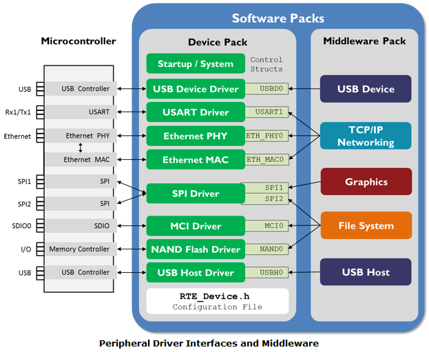
CMSIS-Driver Software Packs (Source: keil.com)
All these software packages are using some way of API. Below is an example from the Freescale Kinetis SDK to read a value from a pin:
/*FUNCTION**********************************************************************  *  * Function Name : GPIO_DRV_ReadPinInput  * Description   : Read current input value of individual GPIO pin.  *  *END**************************************************************************/ uint32_t GPIO_DRV_ReadPinInput(uint32_t pinName) {     GPIO_Type * gpioBase = g_gpioBase[GPIO_EXTRACT_PORT(pinName)];     uint32_t pin = GPIO_EXTRACT_PIN(pinName);     return GPIO_HAL_ReadPinInput(gpioBase, pin); }It shows a generic and layered approach and is using a HAL (Hardware Abstraction Layer) function:
/*!  * @brief Reads the current input value of the individual GPIO pin.  *  * @param base  GPIO base pointer(PTA, PTB, PTC, etc.)  * @param pin  GPIO port pin number  * @return GPIO port input value  *         - 0: Pin logic level is 0, or is not configured for use by digital function.  *         - 1: Pin logic level is 1  */ static inline uint32_t GPIO_HAL_ReadPinInput(GPIO_Type * base, uint32_t pin) {     assert(pin < 32); return (GPIO_RD_PDIR(base) >> pin) & 1U; }Purists will now start crying “What? Such an overhead for only reading a pin value? I can write that in one line of code!”. But the point here is not that much about code efficience (btw, the compiler should be able to inline the HAL code), but more about if I have to write that myself or if I can re-use something existing. But if using such libraries, it means learning them, and adopting to the philosophy and style of that library. And here is a catch: I would like to have my application code working on multiple platforms, potentially from different vendors. But because the libraries from the silicon vendors are each using their own style/approach, porting the application to another device is not as easy as it could be. Here the approach from ARM with the CMSIS-Driver and CMSIS-Pack (as distribution method) really makes sense.
💡 The challenge might be if the silicon (and tool) vendors will adopt such an approach. At the end, it helps the customer to easily migrate from one device (or vendor) to another. In the automotive space, the users have formed the AUTOSAR group to make that happen. Basically enforcing a common API and way to talk to the hardware.
Software Packages: Pros and Cons
Instead to develop my own drivers, I can use the one provided by a vendor. Typically it covers multiple devices or all devices of a family, so I can use the same API. While this provides portability, it is only for one vendor. Even if the licensing is open source, vendors try to restrict for their own devices only.
The software packages are a much more generic way than the snippets. But because of their generality, they come with overhead. The overhead is typically because of all the generic configuration structures (needing RAM!) and parameterization.
| Pros | Cons |
| For Multiple devices/families | Learning curve |
| Portability | Overhead |
4. Driver Configuration and Generation
Similar to the initialization code tools, there is a class of tools which makes the software libraries and the usage of drivers easier. A few examples of such tools are
- Infineon provides DAVE for their devices.
- Freescale offers Processor Expert.
- STMicroelectronics has STM32Cube.
These tools either are able to configure the software libraries discussed before (e.g. Processor Expert can create configuration structures and files for the Kinetis SDK), or the are directly generating the drivers (e.g. DAVE, STM32Cube or Processor Expert).
Basically these tools ‘know’ the thousands of pages of the reference manuals, and help me with a graphical front end to write my code. Some of these tools (e.g. Freescales Processor Expert) are integrated into an IDE, others are standalone tools (e.g. STM32Cube), or they could be web based (e.g. mbed, but this is somewhat different, as more of on online IDE with driver libraries).
STMicroelectronics has the ‘Cube’:
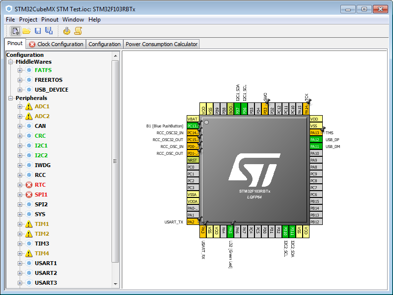
STM32Cube Main view (STMicroelectronics)
Freescale has Processor Expert integrated in CodeWarrior and Eclipse based IDE’s:
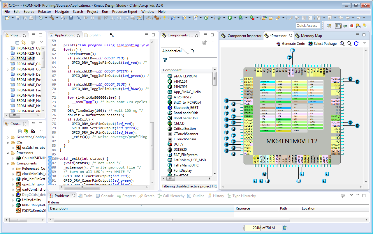
Processor Expert in Kinetis Design Studio (Freescale)
Like the initialization tools, these tools have built-in knowledge of the device I’m using. So they can configure and/or generate the necessary drivers. And they are able to flag any conflicts (e.g. using an interrupt twice, or using an I2C clock which is too high).
The tools can direclty generate files for a project for the IDE’s they support, or they provide source and header files to be intergrated into the application.
A unique feature of Processor Expert is that I can create my own drivers and code generation and share it with the development team:

Custom Library Components
Driver Configuration: Pros and Cons
I see driver and code configuration as the ‘high-end’ tools: they simplify application development a lot, but the same time as any other tool, they have a learning curve. The advantage of these tools is that they have a ‘global’ view and therefore can optimize the drivers for that use case. On the other side that kind of optimization can change the driver source code depending on the settings, which can be seen as ‘dynamic’ source code: doing a wrong setting in the tool can affect the drivers generated or configured. That’s why most of these tools offer a ‘static’ configuration too: only header/configuration files are created, while the driver code itself remains ‘static’. On the positive side these tools making using complex devices much easier.
| Pros | Cons |
| Optimized libraries | Tools learning curve |
| Easy configuration | Possible ‘dynamics’ |
5. Application Examples
All the above items are bits and pieces to build my own application. What is of great value is to have an example of something similar. That might be an open source project someone is sharing on the internet (GitHub is a great ressource for projects, and I share my projects on GitHub too).
Other than that, I check out the application note and project which are provided by the vendors like NXP:
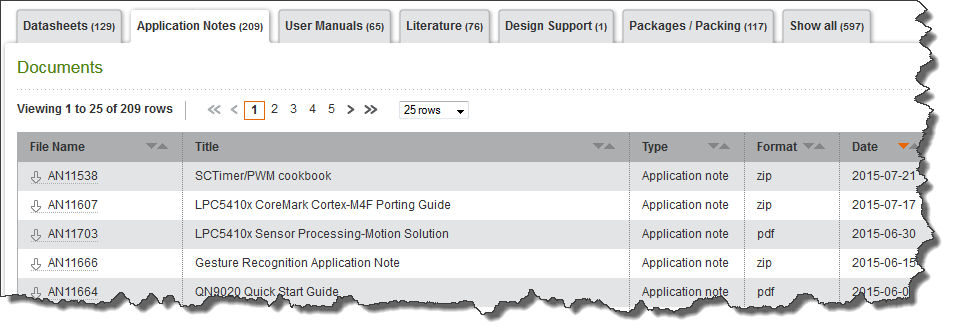
NXP Application Note Library (www.nxp.com)
The application note explain things like “how to write an ethernet enabled application” or “how to implement a USB bootloader” for a certain device or device family. Things are described typically in PDF format:

Freescale Application Note (Source: Freescale)
Usually they come with an example project, for one or more tool chains/IDE’s and the user is expected to take that and adopt it to his own needs.

Application Note with Code Examples
The examples come in different style and quality and are in many cases unmaintaned. While these application notes are a good learning source, they are quickly outdated.
Silicon Labs Simplicity Studio (Eclipse based :-)) comes with an ‘application note’ browser which makes it easy to find the topic I’m interested in:
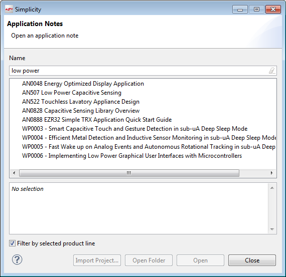
Silicon Labs Application Notes
The Software Libraries mentioned typically have examples included too:

Kinetis SDK Examples (Freescale)
Application Notes: Pros and Cons
Application notes come with a description and usually explain what and why something has to be done. They come with a project and example code (but might not cover the IDE I’m using) and it gives me a great starting point. But it might be very hard to use it for a different device or build environment/compiler. And I have found that many application notes very soon might be outdated because the device or tools have been changed.
| Pros | Cons |
| Explained | Limited transfer to different device |
| Project/Example | Might be outdated |
The application notes and examples are a great learning source. They usually explain the inner workings better than the reference manual of the device. Additionally application notes show how things work together.
Summary
When developing an application, I consider multiple helpers: from source snippets in the forums, tools to provide code for muxing, pin configuration, clocking and low power modes, software and driver libraries, code configuration and generation tools up to application notes an example projects. It takes time and experience to combine all these together, but at the end they are all great helpers.
One thing I notice that configuration and generation tools are discussed very controversal: it seems to me that one half of the users hate it, and one half really loves it. Code generation tools (like Processor Expert) are very powerful, but they are not perfect for everyone. It seems to me that these tools are like the C/C++ compilers when they got introduced 20 years ago for embedded: the ones doing assembly programming did not like the compilers for many reasons. But they allowed a huge productivity step. Still, assembly is still around and needed. My thinking is that it is not about if something is good or bad: it is about using the right tool to get the job done :-).
Happy Helping 🙂

Great overview Erich, and fascinating to get all the tools. I don’t how you cover so many – and manage some great code.
When looking at a new product – I think of an “edges in design” – what is the most difficult area that needs prototyping, software and hardware – usually something that is a core pain to my customers. When that is prototyped and proven, then there is the hard work of building the whole product,usually a lot of legacy expectations, what my customer just assumes will be there – and alot of work – and thats where the libraries come in really useful.
LikeLike
Hi Neil,
I agree on the “edges of design”. And I agree on the hard work part too. What I always find difficult is to get things working properly which actually should work from other projects (like re-using the file system part, etc): I still feel I’m always tend to underestimate that final integration work. So even if there are libraries, it will take a large amount of time to get them intergrated and working.
LikeLike
System Integration for an embedded software product release is the final slog – I design my code with a special embedded way of tracking module path execution.
In the early days of embedded coding we tried to design each unit correctly – and then integrate and track bugs with expensive emulators. Became very painful in large systems.
Now I design from the start thinking about system integration – usually with a number of embedded processors in the path. I start with thinking of an optimal minimal customer configuration in a defined test setting – quite expensive in terms of systems – and how to run it for a defined “test forever” – usually 1day to 1week. When designing code I put in debug statements that can be turned on at run time. Then when an anomly shows up, I turn on targeted appropiate runtime debug through the debugShell to monitor what path the code is taking to generate.
The run time overhead deubg check is usually just checking one variable
if (MODULE_DEBUG & localDebug){OutputModuleDebugContext;}
LikeLike
Hi Erich – in case you haven’t noticed recent posts containing code snippets are not displaying characters like ‘&’ correctly and are instead displaying the raw HTML entity &. This makes the code snippets difficult to read. E.g.:
return (GPIO_RD_PDIR(base) >> pin) & 1U;
}
🙂
LikeLike
Should have read “the raw HTML entity &_amp; without the underscore…
LikeLike
Yes, I have noticed :-(. And desperately fixing it, only that it gets screwed up again the next day. Something wrong with wordpress who tries to translate everthing into HTML code. I have not found a fix for it (yet) 😦
LikeLike
No problem. Just wanted to point it out in case you hadn’t noticed.
LikeLike
I might have found a solution: instead using ‘sourcecode’ in the text it seems that ‘code’ works better (fingers crossing!). I checked the WordPress help, and in the past they had ‘sourcecode’ in the documentation, but now it is only ‘code’. I had not noticed that change. Or I had it wrong from the beginnig.
Thanks for pointing it out.
LikeLike
Hi Erich,
Thank you for this comprehensive summary, it summarizes in a very fine manner the tools of each manufacturer. Thank you for your blog, I always advise my students to read it! Best regards. Serge
LikeLike
Hi Serge,
thank you. There is so much more to write about each of the tools, and there are many more pros and cons. But I felt I have to start with something.
LikeLike
HI Erich,
I first got involved with microcontrollers in 1997. Eight bit MCUs were the norm in those days. 16 bits were just coming out. I was able to teach myself everything I needed to know to bring a product to market in about a year or so.
I moved out of the MCU market for several years and a few years ago started teaching myself MCUs once again.
As you know, technology doubles its complexity every two years or so. Consequently, I now have to know 512 times as much as I did in ’97. That is an increase of 51,200 percent!!!
In 18 to 24 months (not very long at all) I will have to learn ANOTHER 51,200 percent just to keep current. It’s enough to make my eyes cross and give me a headache just thinking about it.
Unfortunately, the silicon manufacturers are only just starting to realize that virtually everyone who uses their products has to teach themselves all the idiosyncrasies of their tools and hardware. Up until the last 18 months or so, in my observation, most silicon vendors assumed that the only people who had any business using their MCUs, etc, should be trained electrical engineers who presumably were already experienced in that vendor’s tools and hardware.
The PRIMARY REASON I got involved with Freescale microcontrollers three years ago was because YOUR BLOG was written to people who were not Freescale engineers. It taught me how to use the Freedom KL-25Z step by step. None of the other vendors had anything like your blog. (Neither did Freescale for that matter. Your blog is your own contribution to the advancement of Freescale MCU technology. And made it possible for me to do my job with Freescale components.) The vendors all assumed that only people who knew how to use their particular MCUs had any business trying to program them.
This was proven by all the stupid simple problems I had to figure out even when using Freescale MCUs and even with the help of your blog. It took me months to get simple programs running on the KL-25 because there was NO INTELLIGIBLE documentation on even how to use the GPIOs, let alone all the other features. Fortunately, you and your blog supported me through this process.
The silicon vendors have support forums, but there is a clear attitude that only experienced engineers with very minute technical questions have any business asking questions on them. As of 12 months ago when I was frequenting the forums of NXP, STM, and Freescale, there was no provision for folks just starting to learn their hardware.
Another great thing about Freescale MCUs is their Processor Expert program. It allows one to configure a Freescale MCU in minutes, whereas it took me months to learn how to do the same thing with STM MCUs 2 years ago. (STM requires a major investment in IDE software to use their MCU config tools. Few independent and small business developers will make that kind of initial investment.)
I think the middle management of the silicon vendors also assume that the people who will be designing with their silicon have infinite time and no outside interests. They assume the designer actually “enjoys” spending weeks wading through obscure and ambiguous documentation to figure out the most basic concepts like how to configure and activate an IO pin. They are blind to the fact that most people who are trying to design a product with their silicon are more interested in getting a product to market with the least amount of effort and self education. The designer’s goal is not to spend two months learning the idiosyncrasies of an arbitrary GPIO mux design. It is to make a working product as soon as possible, and then get back home to his or her family.
With technology doubling every two years, it is impossible for anyone to stay current with new MCU hardware and tools. Therefore, everyone in the MCU field has to be constantly teaching themselves how to use the new hardware and software. I believe that the silicon vendor that realizes this and supports it will have a powerful impact on the market.
This is why Arduino, Raspberry Pi, and my favorite, the BeagleBone Black are so popular. They are easier to self teach than what the major silicon vendors offer.
(I admit that these opinions are based on the MCU market as of 12-18 months ago. Much may have changed since then. For the last year I have been working with the BeagleBone Black exclusively. But for some reason, there is a lot to learn about that platform as well. LOL)
LikeLike
Thanks for this very detailed view and feedback! I don’t think the MCU market has changed much the last 12-18 months. What you have described even has accelerated more. To me, it seems to be far too easy and simple to produce new silicon/devices/microcontrollers: it is probably a great achievement of the silicon designers that they can do this so easily: take a few libraries, add an ARM core and bang: you have a new device on the market. It only seems to me that the errata list (if published at all or if complete?) gets longer and longer.
What the industry struggles in my view is with the software and tools: while producing a new piece of microcontroller seems to be a matter of months, writing good software and middleware for it takes longer and longer. And there are simply too many different devices, so so software for it gets thinner and thinner. And therefore the blogs/tutorials/etc gets less and less for a device too.
Why is the BeagleBone or a Raspy so great? Not because there are so many microcontrollers for it, or because it is the best microcontroller of the world on it. Because there are only few version/variants/boards, so developers can focus on the few ones and get things right, instead of spreading too thin.
I think all these custom devices are great for the big customers, because they order millions of one device type, but write the software once (with a team of say 50 or more engineers). It works for them. And probably they are one of very few customers for that device anyway, and they do not (need to?) care.
But that model does not work for the rest of the world where the “silicon is just sand” and where the software, tools and middle ware counts more than a 5-10 cent cheaper device.
But what I think is going on as a major shift: I see projects or users who have used in the past an Arduino board or even a (custom) microcontroller board to a new model: for small series they are going to buy Raspberries and BeagleBones and using them in their design. Distributors starting to limit the number of Raspys and BBones you can order because companies start using hundreds of them in their product. And they are faster and better developing their projects and products with these boards because of the massive amount of tutorials, blogs and information about these platforms.
I don’t know where things will be going, but I think there will be even more change, more consolidation and at a faster pace. We will see 🙂
LikeLike
Well said. Thank you.
Perhaps a niche market is opening up for trainers, and software development companies, to bridge the gap between MCU vendors and new product development end users. (But who can keep up with the technology doubling every 18-24 months?)
LikeLiked by 1 person
There is definitely a market for that kind of trainings, but it is rather small. At least in my area I don’t see any 3rd party training on microcontrollers and that kind of things. There are trainings from tools and silicon vendors (not that many), and they rather aim to ‘sell’ and not to ‘train’. The only relevant training I see really available is (yet again) on Raspy, Arduino and BeagleBone boards and projects. And I see that makes sense: they are focused on knowledge transfer and trainings, you get a lot of value with the board and tools, and there is a large community. Looking at the local FabLabs and Hackerspaces, they are RAB (Raspy/Arduino/BeeagleBone) dominated.
LikeLike
Pingback: Overview: Processor Expert | MCU on Eclipse